1
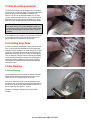
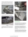
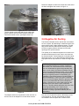
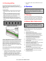
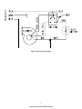
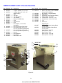
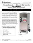
PHOENIX GUARDIAN
H. E. P. A.
SYSTEM
Therma-Stor Products
Box 8050 Madison, WI 53708
Toll Free 1-800-533-7533
Local 1-608-222-5301
PHOENIX GUARDIAN Operation & Service Instructions
Table of Contents
1 Specifications
1. Specifications ......................................................... 1
2. Operation................................................................. 1
2.1
Transporting the Phoenix Guardian ........... 1
2.2
Location...................................................... 1
2.3
Electrical Requirements ............................. 2
2.4
Limiting Amp Draw ..................................... 2
2.5
Air Ducting.................................................. 2
2.5a Inlet Ducting ............................................... 2
2.5b Outlet Ducting ............................................ 3
2.6
Negative Air Ducting .................................. 4
2.7
Power/Speed Switch .................................. 5
2.8
Hour Meter ................................................. 5
3. Maintenance ............................................................ 5
3.1
Air Filters .................................................... 5
3.1a Carbon/Potassium Permanganate Filter.... 5
3.2
Checking Airflow ........................................ 6
Model:
Phoenix Guardian
Electrical: 110-120 Vac, 12 Amps, grounded
Airflow: Hi speed: 1400 CFM w/o external ducting
Lo speed: 900 CFM w/o external ducting
Duct Connections:
Inlet:
18” diameter: 18” flex duct can be connected
directly to the top; 12” dia. adapter for flex duct
Outlet: 10.5” square: (3) Rectangular wire-form collars
for lay-flat plastic ducting; (1) for 14” & (2) for
10”; 12” diameter adapter for flex duct
Size:
25” wide (26.5” over axle)
28" deep w/ handle
39" tall
Weight: 121 lbs.
2 Operation
4. Service ..................................................................... 6
4.1
Warranty..................................................... 6
4.2
Blower Motor Replacement........................ 6
2.1 Transporting the Phoenix
5. Wiring Diagram ....................................................... 7
The Phoenix Guardian should be upright when
transported by vehicle. It may be tipped on to its back for
loading and moving by hand.
6. Service Parts List.................................................... 8
2.2 Location
Serial No. ________________________________
Purchase Date ____________________________
Dealer's Name ____________________________
Read the operation and maintenance instructions
carefully before using this unit. Proper adherence to
these instructions is essential to obtain maximum benefit
from your Phoenix Guardian dehumidifier.
Note the following precautions when locating the Phoenix
Guardian:
• It is designed to be used INDOORS ONLY.
• If used in a wet area, plug it into a GROUND FAULT
INTERRUPTER.
• DO NOT use the Phoenix Guardian as a bench or
table.
• It must always be used in the upright position.
• The air inlet on top & the front outlet should be at
least 1 foot from walls and other obstructions to
airflow.
Lit. No. TS-265-0602
www.sylvane.com 1-800-934-9194
2.3 Electrical Requirements
The Phoenix Guardian can be plugged into a grounded
15 Amp circuit. It draws12 Amps or less with clean filters
and no ducting (if less amperage is available, see
Section 2.4). Due to the high percentage of a 15 Amp
circuit’s capacity that the unit uses, the circuit should be
dedicated to running the Phoenix Guardian only. Amp
draw decreases as filters get dirty and ducting is added.
CAUTION: The unit must always be operated with all
three filters and the top in place. Operating it with one
or more filters missing, the top off, and/or inferior filters
will cause the amperage to increase and the motor to
overload.
Figure 1
If an extension cord is required, it must have a minimum
of 12 gauge conductors if 25 feet long or less and 10
gauge conductors if greater than 25 feet long.
2.4 Limiting Amp Draw
In certain conditions, allowing the unit to draw its normal
10 to 12 Amps may be undesirable. Limited amperage
available may be needed to run other equipment. In such
conditions, amp draw can be reduced by restricting the
airflow at the inlet with the unit running on either speed.
The 18” diameter inlet grid can be restricted by partially
covering it with anything convenient and stiff enough to
maintain its shape (cardboard, sheet metal, plywood)
The negative air pressure at the inlet will help hold the
restrictor in place.
2.5 Air Ducting
Figure 2
2.5a Inlet Ducting
Occasionally the area to be filtered is difficult to access
and/or the unit cannot be located in the area. In such
cases, the air can be ducted to the unit’s inlet.
A round 18” diameter flex duct can be attached to the
unit inlet on top. It connects by hooking the spiral wire of
the flex duct under the four tabs inside the perimeter of
the inlet opening; see figures 1, 2 and 3.
Flexible 18” ducting is available from Therma-Stor
Products.
Figure 3
2
www.sylvane.com 1-800-934-9194
An adapter is included that allows 12” flexible ducting to
be connected to the inlet. It is stored on the unit’s side.
Flex duct is pushed through the adapter center with the
adapter hooking tabs facing away from duct; (see figure
4).
Figure 6
Figure 4
The spiral wire passes from one side of the adapter to
the other via the notch on the hole edge; (see figure 5).
Figure 7
2.5b Outlet Ducting
Three rectangular wire-form collars are supplied that will
allow round lay-flat plastic ducts to be attached to the
Phoenix Guardian outlet. The two small collars are made
for 10” lay-flat duct; the large one is for 14”. Lay-flat
plastic ducting is available from Therma-Stor.
Figure 5
To attach ducting to a collar, remove the collar from the
unit by loosening the two wing knobs above the collars
and sliding the collar out. Put the plastic duct end
through the collar center from the front. Fold the duct end
outward so that it overlaps the outside of the collar by
several inches.
The adapter and duct are positioned on the unit top with
the four tabs placed into the slots. The adapter is then
twisted counterclockwise to lock it in place; see figures 6
and 7.
The same adapter that allows 12” flexible ducting to be
connected to the inlet can be used to connect 12” flexible
duct to the outlet. It is stored on the unit’s side. Flex duct
is pushed through the adapter center with the adapter
hooking tabs facing toward the duct, (see figure 8 and 5).
3
www.sylvane.com 1-800-934-9194
Rotate the adapter so the thumb screws are at the end of
the slots and tighten the screws; see figure 11.
Figure 8
The four thumb screws that hold the two outlet collar
guides must be removed; set the guides aside and
reinstall the thumb screws, (see figures 9 and 10).
Figure 11
2.6 Negative Air Ducting
The Phoenix Guardian can be used to filter and exhaust
air from a space. By exhausting to outside the space, the
space will be under a slight negative pressure. This will
help prevent airborne particles from leaving the space,
since the negative pressure will draw air in through
openings in the space’s exterior.
The quantity of air exhausted depends on how the unit is
ducted and which speed is used. One or two ducts can
be directed outside. If all the filtered air is ducted outside,
this would result in up to 1300 CFM being exhausted on
high speed and an equal amount of fresh air being drawn
in.
Figure 9
CAUTION: Exhausting too much air from a space with
open combustion devices (e.g. furnace, fireplace or
water heater) can cause those devices to backdraft.
This can contaminate the space with potentially fatal
gases. In such cases, the Phoenix Guardian must be
used in one of the following three ways: (A) as a filtering
unit only. Exhausting no air from the space and thus
causing no negative pressure or backdrafting. (B)
Exhausting a very limited amount of air which does not
cause backdrafting. In case B, the open combustion
devices must be thoroughly checked to guarantee that
they do not backdraft while the Phoenix Guardian is
running. (C) direct one or more outlet ducts from the
Guardian to the room with the open combustion
device(s). This will positively pressurize the room, thus
preventing backdrafting. As in case B, those
combustion devices must be checked after the
Guardian is running to guarantee that they are not
backdrafting.
Figure 10
One duct can be directed outside, exhausting a portion
of the filtered air. The rest of the filtered air can be
recirculated inside the space with or without outlet
The adapter and duct are positioned on the unit front so
the four slots in the adapter fit over the thumb screws.
4
www.sylvane.com 1-800-934-9194
ducting. Varying the collars’ position in the guides at the
outlet can control the quantity of air exhausted. To
determine precisely the amount exhausted, an airflow
meter is required.
it is visibly dirty or when it is contaminated by a
previous job.
B. 25 to 30% efficient (per ASHRAE 52.1-1992) pleated
fabric filter. Actual size is 23-3/8” x 23-3/8” x 1-3/4”.
This filter should be changed when airflow is reduced
or it is contaminated by a previous job.
C. 99.97% DOP efficient HEPA filter. Actual size is 233/8"”x 23-3/8” x 12-1/2. It contains at least 175 sq. ft.
of media. This filter should be changed when airflow
is reduced or it is contaminated by a previous job.
2.7 Power/Speed Switch
The power/speed switch is located on the unit side.
When turned on to high or low speed, it powers the
blower and hour meter.
3.1A Activated Carbon/ Potassium
Permanganate Filters
OCCASSIONALLY THE BLOWER MAY NOT
START ON LOW SPEED. IF THIS OCCURS,
START THE UNIT ON HIGH SPEED, THEN
SWITCH IT TO LOW SPEED.
Two optional gas phase filters are available from
Therma-Stor: a disposable and a refillable. Each uses a
blend of activated carbon and potassium permanganate.
This blend removes the vast majority of contaminants
encountered in most filtering applications. The activated
carbon removes the heavier volatile organics while the
potassium permanganate removes lower molecular
weight contaminants. This is well suited to the smoke
odors present after fire damage.
CAUTION: Do not remove the top to access the filters
with the unit on. Removing the top and filters while
running can: (A) damage the blower motor by causing
it to overload, (B) expose potentially fatal high voltage
electrical parts, (C) expose the dangerous rotating
blower impeller.
The life of the media blend depends upon both the hours
used and the contamination level. Another advantage of
the blended media versus activated carbon only is that
part of the blend changes color as it loads up with
contaminants. It starts out black, then turns pink, then
brown, and finally white. It is best changed when it
passes the brown stage and begins to turn white. It has
lost most of its effectiveness at that point. When these
filters are installed, the pad filter does not need to be
installed above them. This allows the operator to check
the media color through the top grill of the unit without
removing the top.
2.8 Hour Meter
A digital hour meter is located near the power switch on
the unit side. It measures the cumulative time that the
unit is turned on to tenths of an hour. It stores its total
when the unit is unplugged. The previous total will be
displayed when the unit is on or off. It resets to zero after
99,999.9 hours of operation.
3 Maintenance
These filters are the same size as the pleated fabric
filter. They are installed above that pleated fabric filter.
The pleated fabric filter catches carbon dust that comes
off these filters before it reaches the HEPA filter.
3.1 Air Filters
The standard Phoenix Guardian is equipped with three
filters that progressively filter out smaller particles. An
optional activated carbon/potassium permanganate filter
can be used, giving a fourth stage of filter media (see
section 3.1a). These filters must be checked regularly.
Operating the unit with dirty filters will reduce the airflow
and current draw, but will do no harm to the unit. The unit
can be run indefinitely with dirty filters.
The refillable carbon filter is metal-framed and can be
refilled with carbon blend media purchased in 5-gallon
buckets. The amount of carbon blend media loaded into
the filter can be adjusted to the particular amount gas/
odor removal required.
The disposable filter contains 7½ pounds of active
media.
CAUTION: The unit must always be operated with all
three filters and the top in place. Operating it with one
or more filters missing, the top off, and/or inferior filters
will cause amperage to increase and may cause the
motor to overload. Permanent damage could result.
The three standard filters used are listed below (as
installed in the unit from top to bottom):
A. Polyester media pad pre-filter. Actual size is 23-3/8”
x 23-3/8” x 1” thick. The white side faces up. This
filter should be replaced when the airflow is reduced,
5
www.sylvane.com 1-800-934-9194
3.2 Checking Airflow
•
An inclined tube manometer is attached to the unit to
determine if the filters need replacing. It measures
negative static pressure between the blower inlet and the
HEPA filter outlet.
4 Service
CAUTION: Servicing the Phoenix Guardian with its
high voltage circuitry presents a health hazard that
could result in death, serious bodily injury, and/or
property damage. Only qualified service people should
service this unit.
To check airflow:
• Remove any inlet or outlet ducting, but leave the top
and all filters in place. Make sure the unit is sitting
level.
• Turn the unit on high speed for at least 15 minutes.
Read the number values for the fluid levels in the
upper and lower tubes. The fluid levels are slanted.
Read the level at the center of both tubes.
• Subtract the lower tube number from the upper tube
number. Match this difference to the chart on the
manometer label to establish the percentage of clean
air flow.
43
100%
51
90%
Calculation
57
60
80%
70%
Percentage
62
60%
If the airflow is still too low, the HEPA filter must be
changed.
4.1 Warranty
A warranty certificate has been enclosed with this unit.
Read it before any repair is initiated. If a warranty repair
is required, call the factory first at 1-800-533-7533 for
warranty claim authorization and technical assistance.
4.2 Blower Motor Replacement
64
50%
OCCASSIONALLY THE BLOWER MAY NOT START
ON LOW SPEED. IF THIS OCCURS, START THE
UNIT ON HIGH SPEED, THEN SWITCH IT TO LOW
SPEED.
The centrifugal blower has a PSC motor and internal
thermal overload protection. Follow the steps below to
change the motor:
1.
2.
3.
Unplug the power cord.
Remove the top and all air filters.
Remove the wire nut that connects the blower’s
white lead to the wire harness. Disconnect the
motor’s green ground wire from the unit. Remove
the black and red wires from the switch.
4. Remove the four nuts that fasten the blower
mounting flanges to the base of the unit.
5. Lift the blower out of the unit.
6. Loosen the set screw that holds the impeller hub to
the motor shaft.
7. Lay the blower on its side, motor up.
8. Remove the 3 screws that fasten the motor support
brackets to the blower housing.
9. Lift out the motor with support brackets.
10. Remove the two screws (one at each motor end)
that hold the support brackets to the motor end
mounting rings.
11. Remove the six screws that hold the support
bracket halves together. Note which holes and slots
they were located in.
12. Reassembling with the new motor is the above
procedure reversed.
Airflow on high speed with all filters clean and no ducting
is about 1400 CFM. The unit can be run with very dirty
filters and virtually no flow without harming the unit. The
operator’s decision to change filters should be based on
filter cost versus the unit’s filtering effectiveness. If
airflow is 700 CFM versus 1400 CFM, the unit will filter
particles from a space at half the rate. The operator must
judge if that is acceptable.
If the operator determines the filters should be changed
due to low airflow, it is most economical to change them
in the following order:
•
•
Change the pad pre-filter (top) first. This is the least
expensive filter. Recheck the airflow. If the airflow is
acceptable, no other filters need to be changed.
Change the pleated fabric filter (middle) second. It is
the second least expensive filter. Recheck the
airflow. If acceptable, the HEPA filter does not need
changing.
6
www.sylvane.com 1-800-934-9194
Figure 13: Electrical Schematic
7
www.sylvane.com 1-800-934-9194
SERVICE PARTS LIST: Phoenix Guardian
Item
1
2
3
4
*
*
*
5
6
*
7
8
9
10
11
12
*
13
14
Part No. Qty. Description
4023374 1
Air Filter, Polyester, 1” x 24” x 24”
4023375 1
Air Filter, Pleated, 2” x 24” x 24”
4024741 1
Air Filter, Hepa, 24” x 24” x 12”
(99.97% DOP)
4024845 1
Axle
4024816 2
Axle Cap
4024817 2
Axle Cap Washer
1242497 2
Axle Washer
4023121 1
Blower (Lau DD10-8A)
4024813 1
Cord
4024811 1
Wire Harness
4024073 2
Foot
4024076 1
Duct Adapter, 12” Flex Duct,
Inlet/Outlet
4024808 2
Duct Guide, Outlet Duct Collar
4024078 2
Duct Outlet Collar 12” X 5.75”
For 10” Lay-Flat Duct (Not Shown)
4024079 1
Duct Outlet Collar 12” X 10.5”
For 14” Lay-Flat Duct (Not Shown)
4024810 1
Handle
4024069 2
Handle Bracket
4021597 1
Hour Meter
4024867 1
Manometer Label
Item Part No. Qty. Description
15 4024873 1
Manometer Tubing
16 4023114 1
Motor, 115V,.75Hp, 1625/1180RPM
(Fasco P/N 7124-2020)
17 4023362 *
Nut, Plastic, ¼-20 (Not Shown)
18 4024083 3
Snap Button
19 4024809 1
Suspension Foam Pad (Not Shown)
20 4024871 1
Switch, DPDT, On-Off-On
21 4024827 6
Thumb Screw, ¼-20 X ½ ” Long
22 4024868 4
Thumb Screw, ¼-20 X 1½” Long
23 4024085 1
Top
24 4021591 2
Wheel, 10"
4023487
4024764
4024528
4024750
4023643
4022537
4024889
1
2
3
Optional Parts
Air Filter, Disposable Carbon Blend
2” X 24” X 24”
Air Filter, Refillable Carbon Blend
2” X 24” X 24”
Carbon Blend, 5 Gal Pail
Duct, Flex, 12” X 25’
Duct, Flex, 18” X 25’
Duct, Lay Flat, 10” X 500’
Duct, Lay Flat, 14” X 500’
INSIDE UNIT
23
18
12
21
9
1
5
16
22
6
14
15
20
13
8
24
4
7
Figure 14.
8
www.sylvane.com 1-800-934-9194