1
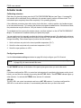
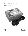
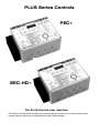
PLUS Series Controls
PEC+
SEC-HD+
The PLUS Control user interface
PLUS Series controls feature a simple and convenient layout that allows you to check system status,
change settings, and ensure only authorized personnel make changes.
Table of contents
Table of contents ...........................................................................................................................................i
Getting started ..............................................................................................................................................1
The Status bar...............................................................................................................................................2
Making adjustments to the system ...............................................................................................................3
Stage mode ..................................................................................................................................................4
Variable speed mode....................................................................................................................................5
Variable speed operation ........................................................................................................................6
Actuator mode ..............................................................................................................................................7
Calibrating actuators...............................................................................................................................7
Configuring actuators .............................................................................................................................7
The growth curve concept ............................................................................................................................9
Setting the growth curve .......................................................................................................................10
Growth curve tips..................................................................................................................................10
Deactivating the growth curve...............................................................................................................11
System access............................................................................................................................................12
Security .................................................................................................................................................12
Master PINs ..........................................................................................................................................12
User PINs..............................................................................................................................................12
Units of measure...................................................................................................................................13
Control ID..............................................................................................................................................13
Special functions ........................................................................................................................................13
Restoring factory settings .....................................................................................................................13
Restoring the master PIN ......................................................................................................................13
Set-point ranges .........................................................................................................................................14
Installing the PLUS control ..........................................................................................................................15
Electrical ratings....................................................................................................................................15
Surge suppression................................................................................................................................15
Mounting Instructions ...........................................................................................................................16
PEC+ board layout...............................................................................................................................17
SEC-HD+ board layout ........................................................................................................................18
Wiring instructions.................................................................................................................................19
Connecting the variable speed stages..................................................................................................19
Connecting the variable speed stages..................................................................................................20
Three-phase wiring ...............................................................................................................................21
Connecting the relay stages .................................................................................................................22
Thermostat input for gas furnace or brooder ........................................................................................22
Connecting an actuator ........................................................................................................................23
Connecting an alarm system ................................................................................................................24
Connecting temperature sensors..........................................................................................................25
Extending the sensor .............................................................................................................................25
i
Networking the control ................................................................................................................................26
Termination resistors.............................................................................................................................26
Wiring the network ................................................................................................................................27
Control messages.......................................................................................................................................28
Troubleshooting ..........................................................................................................................................28
Care and maintenance ...............................................................................................................................28
Maintenance .........................................................................................................................................28
Additional tips .............................................................................................................................................28
Setup worksheets .......................................................................................................................................28
Variable stage settings..........................................................................................................................28
Relay stage settings..............................................................................................................................28
Inlet actuator settings............................................................................................................................28
Growth curve setup...............................................................................................................................28
Service and technical assistance ................................................................................................................28
ii
PLUS user manual
Getting started
Getting started
Thank-you for purchasing a Phason PLUS control. This manual will help you get the most out of your
PLUS control. Read the manual before installing and configuring your PLUS control.
See Installing the PLUS control on page 15 for installation and wiring instructions. The equipment
connected to the PLUS control must not draw more current than what the control stages are rated.
Equipment that is rated higher than the control ratings will damage the control and void the warranty.
Fill out the Variable speed settings, Relay stage settings, and Inlet actuator settings worksheets.
Use these set-up sheets when making changes to the control’s set points.
If you plan to use the growth curve, fill out the Growth curve setup sheet, and then program the
growth curve settings before adjusting the individual stages.
170057 rev 13
1
The Status bar
Phason
The Status bar
The Status Bar shows the present status of all stages of the PLUS Control.
NOTE
The PEC+ layout is shown. The SEC-HD+ has only three relay stages and one actuator
stage.
•
The Alarm indicator lights up when an alarm condition exists.
•
The variable speed indicators, VS-1 and VS-2, light up when power is being supplied to variable
speed fans 1 and 2. You may notice one of these indicator lights glowing fainter than the other, the
fan represented by the fainter light, is running at less than full speed.
•
The stage indicators, ST-1 to ST-6 (ST-1 to ST-3 for the SEC-HD+), indicate which relays are ON
or OFF.
•
The TEMP indicator lights up when the digital display is showing a temperature.
•
The TIME indicator lights up when the display is showing a time setting. Two digits to the right of
the decimal will be shown when the value is less than 10.0 minutes and only one when the value is
10.0 minutes or greater.
•
The SPEED indicator lights up when the display is showing a speed value (0 to 100%).
•
The POS indicator lights up when the display is showing a position value (0 to 100%).
•
Pressing Max/Min displays the maximum ambient temperature in the room or zone over the
previous 24 hours, press it again to display the minimum ambient temperature over the previous 24
hours.
•
The display “blinks” in this mode. This lets you know the displayed temperature is not the current
temperature. If you press the button again, it will restore the current ambient temperature. If you
forget, the control will display the current ambient temperature in a few seconds.
2
2005-04-13
PLUS user manual
Making adjustments to the system
Making adjustments to the system
The OK button saves changes. The display shows Acc (accepted) when you press OK. If the display
shows PIN, you must enter your PIN (personal identification number) before the settings will be
accepted. The control will NOT save the changes until you press OK.
The Mode button allows you to scroll through the programming modes. A green indicator lights up in
the active panel (STAGE MODE, VSP MODE, ACT MODE, or G.C.MODE.)
The Up button allows you to increase the value on the display. Holding the button will cause the
settings to change at a faster rate
The Down button allows you to decrease the value on the display. Holding the button will cause the
settings to change at a faster rate.
170057 rev 13
3
Stage mode
Phason
Stage mode
Use the Relay stage settings worksheet on page 28 to help configure your PLUS control.
NOTE
The PEC+ layout is shown. The SEC-HD+ has only three relay stages. You must press OK
after each change to save the settings.
The STAGE MODE indicator at the bottom right of the panel glows green when
you are in stage mode.
On the PEC+, the Stage 1 to 4 indicators light up if two inlet actuators are
connected to the control. If only Stage 1 and 2 are illuminated, only one inlet
actuator is connected. If no indicators are lit up in the left column, no inlet
actuators are connected.
On the SEC-HD+, the Stage 1 and 2 indicators light up if an inlet actuator is
connected to the control. If no indicators are lit up, no inlet actuators are
connected.
The SEL button scrolls through the stages and the Alarm Hi/Lo. The indicators
in the left column light up when you select the corresponding stage. If you scroll
past your desired stage, keep scrolling through the stages by pressing SEL until
you reach it.
Heat or cool
You must designate a relay stage as either heat or cool. To do this, press the
H/C button. The HEAT indicator lights up when you assign the stage as ‘heat’.
The COOL indicator lights up when you assign the stage as ‘cool’. You cannot
assign a relay as a ‘heat’ or ‘cool’ stage if it has been assigned to an actuator.
Duty cycle
You can designate a relay stage as a duty cycle relay stage (after designating it as either heat or cool)
by using the O/C Time (relay open/relay closed time) button to set an ON and OFF duration for the
relay. The most common uses for this are misters and curtain machines.
The ON time is the duration a relay is active. The ON indicator lights up when this mode is selected.
The OFF time is the duration a relay is inactive. The OFF indicator lights up when this mode is
selected. The duration is set in hundredths of a minute. See the example below.
Toggle to ON to set the ON time for the relay. The digital display will show the current setting, use the
Up or Down buttons to adjust the duration the relay will be closed (active).
Toggle to OFF to set the OFF time for the relay. The digital display will show the current setting, use
the Up or Down buttons to adjust the duration the relay will be open (inactive).
Example: If you set the ON time to 100 and the OFF time to 500, the relay will be active for one
minute, then inactive for five minutes. When the temperature rises above the set point for a cooling
stage (falls below for a heating stage), the relay will be active for one minute, then inactive for five
minutes. After the five minutes, the control does a check; if the temperature is still above the set point,
the relay will be active again for one minute, then inactive for five minutes.
4
2005-04-13
PLUS user manual
Variable speed mode
Variable speed mode
Use the Variable stage settings worksheet on page 28 to help configure your PLUS control.
The VSP MODE indicator at the bottom right corner of the panel glows green when you are in variable
speed mode.
Press VSP Sel to select the variable stage. The VSP-1 or VSP-2
indicator lights up beside the active stage.
Each time you press VSP Fn, a different function is selected. The
indicator light glows red beside the active function. If you miss the
function you want to adjust, or need to make changes to a
function, press the VSP Fn button to scroll through the functions
until the desired function is active.
Repeat the steps below for each variable stage.
Range
Range is the temperature at which the fan hits full speed (maximum ventilation). When the Range
indicator is lit, you can adjust the Range by pressing Up or Down. The Range cannot be below the
temperature set point (Temp SP). Press OK to save the setting, and then press VSP Fn to move to the
next function.
Temp SP
Temp SP is the desired or ‘target’ temperature for the room or zone. It is also the point at which the fan
will start to increase from minimum idle to full speed. When the Temp SP indicator is lit, you can adjust
the Temp SP by pressing Up or Down. This setting cannot be above the Range or below the idle off
setting. Press OK to save the setting, and then press VSP Fn to move to the next function.
Minimum idle
Minimum idle is the speed the fan will operate at when the temperature is between the Idle off and
Temp SP settings. It is a percentage of full speed. When the Min idle indicator is lit, you can adjust the
Minimum idle speed by pressing Up or Down. Press OK to save the setting, and then press VSP Fn to
move to the next function.
Idle off
Idle off is the temperature at which the fan turns off. When the Idle off indicator is lit, you can adjust the
Idle off temperature by pressing Up or Down. This setting cannot be above the Temp SP. Press OK to
save the setting, and then press VSP Fn to move to the next function.
NOTE
You must press OK after each change to save the settings.
170057 rev 13
5
Variable speed mode
Phason
Variable speed operation
Function
Temp SP
Setting
Range
80°F
86°F
Idle off
75°F
Min idle
20% of maximum ventilation
Variable speed output
The fan is at full speed.
Range
Fan speed increases as the
temperature increases, or
decreases as the temperature
decreases.
Temp SP
The fan is at the minimum idle
speed
Idle off
The fan is off.
Fan speed
Figure 1: Variable speed operation
6
2005-04-13
PLUS user manual
Actuator mode
Actuator mode
Calibrating actuators
Each time you place the jumper over the ACTUATOR PRESENT IN pins (see Figure 11 on page 23),
the actuator will be calibrated. During calibration, the actuator opens, pauses, and then closes. The
inlet should open completely then close completely if it is operating properly.
If the calibration procedure stops after closing for the first time, or fails to position, the feedback signal
is not connected correctly. Try reversing the positive and negative feedback wires. If this does not work,
the potentiometer may be defective. Call your dealer for further assistance.
To recalibrate an inlet, remove the actuator jumper, and then replace it on the ACTUATOR PRESENT
IN pins. The actuator will recalibrate when you replace the jumper.
You can position an inlet manually provided the inlet has calibrated correctly. By adjusting the minimum
position setting, you can manually set the position of the inlet. The inlet will stay at this position until you
change the setting. Follow these steps to position the inlet manually.
1. Set the minimum set point to the lowest possible temperature (32°F).
2. Set all the other set points to the maximum temperature (110°F).
3. Set all the open positions to 100%.
Configuring actuators
Use the Inlet actuator settings worksheet on page 28 to help configure your PLUS control.
NOTE
If you have not positioned the jumper on the circuit board to use an actuator (see Figure 11
on page 23) you cannot access this mode.
The ACT MODE indicator at the bottom of the panel glows green when you are in this mode.
PEC+
If you have configured the PEC+ to control two inlet actuators (by positioning the jumpers on the circuit
board), you can select the actuator by pressing the ACT SEL button. The ACT1SEL indicator lights up
when actuator 1 is selected, ACT2SEL when actuator 2 is selected.
SEC-HD+
The SEC-HD+ can control one actuator and has no ACT SEL selector. If you have configured the
SEC-HD+ to work with an actuator, it is automatically selected when you are in this mode
170057 rev 13
7
Actuator mode
Phason
Each time you press the ACT Fn button, a different function is selected.
The indicator light glows red beside the active function. If you scroll past
the function you want to adjust, press the ACT Fn button to scroll through
the functions until you reach the desired function.
Minimum Position
Minimum Position is the percentage the actuator will be open when the
temperature is at Minimum. When the Min Position indicator is lit, you can
adjust the minimum position by pressing Up or Down. Select a position
adequate to support minimum ventilation. Press OK to save the setting,
and then press ACT Fn to move to the next function.
Minimum
Minimum is the temperature set point for the actuator. Below this point, the
inlet is closed. When the Minimum indicator is lit, you can adjust the
minimum temperature by pressing Up or Down. Press OK to save the
setting, and then press ACT Fn to move to the next function.
Follow the steps below for each stage.
Stage Set Point
Stage Set Point is the temperature set point for that stage of the actuator cycle. When the Stage 1 Set
Pt indicator is lit, you can adjust the temperature set point for Stage 1 of the cycle by pressing the Up
or Down buttons. Press the OK button to save the setting, and then press ACT Fn to move to the next
function.
Open Range
Open Range consists of temperature and position settings.
Open Range (temperature) is the temperature at which the actuator stops opening for the present
stage. When the Open Range indicator and the TEMP indicator are lit, you can adjust the set point by
pressing Up or Down. Press OK to save the setting, and then press ACT Fn to move to the next
function.
Open Range (position) is the percentage the actuator will be open when the temperature reaches the
Open Range (temperature). When the Open Range indicator and the POS indicator are lit, you can
adjust the position by pressing Up or Down. The actuator will open to this position proportionally as the
temperature rises from the Stage Set Point to the Open Range (temperature). Press OK to save the
setting, and then press ACT Fn to move to the next function.
NOTE
8
You must press OK after each change to save the settings.
2005-04-13
PLUS user manual
The growth curve concept
The growth curve concept
The growth curve allows you to select a period where the temperature set points in a zone or room are
adjusted automatically.
The growth curve set points are group set points. In other words, the individual set points for the
variable and fixed stages will be adjusted without losing the relationship between these stages. This
extremely powerful feature allows ventilation strategies to be put in place. Set points will change as
they should, but the relationship between stages will remain consistent.
You can use the growth curve to automatically change the set points for the stages in each step. Once
you program the growth curve, the control makes the changes to the set points once every 24 hours.
The PLUS control has an internal timer that counts 24-hour periods (days). The count begins when the
control is first powered up. In the event of a power interruption, the day count will be retained, but the
time elapsed in the current day will be reset to zero. You can reset the day count to zero by restoring
the factory settings (see Restoring factory settings on page 13)
The growth curve proportionally changes the current settings towards the next growth curve point over
the duration for the current set point. During the seventh growth curve point, the set point remains
constant. When the seventh growth curve point is complete, the growth curve restarts at step 1 with the
step 1 settings. This is shown in the graph below.
170057 rev 13
9
The growth curve concept
Phason
Setting the growth curve
The G.C. MODE indicator in the bottom right of the panel glows green when you are in this mode.
The growth curve is not active when the control is shipped from the factory. The growth curve activates
when the duration for step 1 is set to a value above zero. Follow the steps below to set up the growth
curve:
1. Press Mode until the G.G. MODE indicator is lit.
2. Press GC Select to select the step you want to modify. One of the seven indicators will glow red to
show which step you are modifying.
3. Press Up or Down to adjust the temperature for the step. The TEMP indicator in the status bar will
be lit up and the digital display will show the setting.
4. Press Temp/Duration to change to the duration setting. Press Up or Down to adjust the duration
for the step. The TIME indicator in the status bar will be lit and the display shows the setting.
5. Press OK to save the settings. The display will flash Acc to show the changes have been accepted.
6. Repeat the process for all seven steps of the growth curve. Press Mode when you have finished
configuring the growth curve.
You can verify the growth curve is active by watching the G.C. MODE indicator while displaying the
ambient temperature. If the indicator flashes, the growth curve is enabled—if it is off, it is not enabled.
Growth curve tips
•
Keep a record of the growth curve settings. See the Growth curve setup worksheet on page 35.
•
ALL seven temperature set points must be set, and all seven time intervals must be set to values
greater than zero or the control will not operate properly.
10
2005-04-13
PLUS user manual
The growth curve concept
•
You can make changes to all settings on the growth curve after it has been activated. If you make
changes to a setting that has already passed in the growth curve cycle, the change will not take
effect until the growth curve restarts.
•
You cannot set a new duration for an active step that is less than the time that has elapsed for that
step. This will cause the growth curve to proceed to the next step.
•
Press GC Select while displaying the ambient temperature to observe the current step of the
growth curve and the number of days until the next step.
•
When you set up the growth curve, set the step 1 temperature equal to the Temp SP for VSP-1.
The Temp SP for VSP-1 is the target temperature.
•
Set the last duration for the last step for a longer period than you will need. This will allow you time
for unexpected delays, cleaning, or other activities before the growth curve restarts its cycle. If the
animals leave earlier than expected, you can always reset the growth curve at step 1.
•
When new animals enter the room, you may want to restart the growth curve at the beginning.
Follow this procedure to restart the growth curve:
1.
Press GC Select while the ambient temperature is displayed and then verify the seventh
growth curve indicator is lit.
2.
Press Mode until the G.C. MODE indicator lights up.
3.
Press GC Select until the growth curve indicator lights up.
4.
Press Temp/Duration and note the duration.
5.
Press Down until the duration is 0 and then press OK. This causes the current growth curve
step to complete. The growth curve will restart at step 1.
6.
Press Mode until the G.C. MODE indicator lights up.
7.
Press GC Select until the seventh indicator lights up.
8.
Press Up and adjust the duration to the previous setting (procedure 4).
9.
Press OK to save the setting.
10. To verify the growth curve has restarted, press Mode until the ambient temperature is
displayed. The G.C. MODE indicator will flash indicating the growth curve is active.
11. Press GC Select to verify the current growth curve step and it’s duration.
•
If you change any of the non-growth curve temperature settings while the growth curve is active,
when the growth curve restarts after step 7, the settings will not return to their original values.
Deactivating the growth curve
•
Reset all durations to zero starting at step 7 and working to step 1
•
Once the last duration is set to zero and Mode is pressed to exit the growth curve, the G.C. Mode
indicator will shut off. This indicates the control is operating in conventional mode. Reset the control
as indicated in the Stage Mode and Variable Speed Mode sections.
170057 rev 13
11
System access
Phason
System access
The System Access buttons control several functions of the PLUS
control.
Security
You can enter a PIN to prevent unwanted changes to the settings. The control has a master PIN and
you can add additional user PIN numbers. The PIN must be a four-digit number consisting of the
numbers one to four. The master PIN must be used to add or remove user PIN numbers, but you can
use any valid PIN to change to the control's settings.
You can disable the security PIN feature by setting the master PIN to 1111. This allows the settings to
be modified without using a PIN. The master PIN is set to 1111 at the factory.
If FAI is displayed after pressing OK (after a PIN number was entered), the PIN number was not
entered correctly.
NOTE:
When the PIN numbers are being entered, they are not shown on the display.
Master PINs
To create a master PIN (when it is set to 1111):
1. Press 1, then OK.
2. Enter the new master PIN (must be four digits) and then press OK.
To change the master PIN:
1. Press 1, then OK.
2. Enter the old master PIN and then press OK.
3. Enter the new master PIN and then press OK.
User PINs
To add a user PIN:
1. Press 2, then OK.
2. Enter the master PIN and then press OK.
3. Press 1, then OK.
4. Enter the new user PIN and then press OK.
12
2005-04-13
PLUS user manual
Special functions
To remove a user PIN:
1. Press 2 and then press OK.
2. Enter the master PIN and then press OK.
3. Press 2 and then press OK.
4. Enter the user PIN you want to remove and then press OK.
Units of measure
To change between Fahrenheit and Celsius temperatures, follow the steps below.
1. Press 4 and then OK.
2. Enter a security PIN (the master or any user PIN), and then press OK.
3. Press Up or Down to change the temperature readout and then press OK.
Control ID
The control ID is a four-digit number that identifies the control when it is networked with other controls.
If you give each control a unique ID number, it makes supervising the controls easier.
To set the control ID number, follow the steps below.
1. Press 3 and then press OK.
2. Enter the master PIN number and then press OK.
3. Enter the four-digit ID number and then press OK.
Special functions
You can perform two special functions:
Restoring factory settings
You can reload the factory settings by pressing Up and Down at the same time while powering up the
control. The factory settings will replace all the current set points and disable the growth curve.
Restoring the master PIN
You can erase the user PIN numbers and restore the master PIN to 1111.
To erase the user PIN numbers and restore the master PIN, follow the steps below.
1. Turn off the power to the control.
2. Press and hold the Up, Down, and 1 buttons while turning on the power to the control. You must
hold the buttons until the ambient temperature displays (about five seconds).
170057 rev 13
13
Set-point ranges
Phason
Set-point ranges
°F
°C
32.0 to 110.0
0.0 to 43.3
Relay stages
Temperature Set Point
Relay stage ON/OFF time
0.00 to 30.0 minutes
Relay stage mode
COOL, HEAT, OFF
Hi Alarm
Lo Alarm Set Pt. to 110.0
Lo Alarm Set Pt. to 43.3
Lo Alarm
32.0 to Hi Alarm Set Pt.
0.0 to Hi Alarm Set Pt.
32.0 to Temp Set Pt.
0.0 to Temp Set Pt.
Variable speed stages
Idle off
Min idle
Temp Set Point
Range
0 to 100 %
Between Min idle and Range settings
Temp Set Pt. to 110.0
Temp Set Pt. to 43.3
Actuator stages
Position settings
Temperature settings
0 to 100 %
32.0 to 110.0
0.0 to 43.3
32.0 to 110.0
0.0 to 43.3
Growth curve
Temperature Set Points
Duration
14
0 to 45 days
2005-04-13
PLUS user manual
Installing the PLUS control
Installing the PLUS control
Only a qualified electrician should install the PLUS control.
CAUTION:
CAUTION:
Turn off the power before installing or servicing the
control.
Install all equipment according to the applicable local
electrical codes.
Electrical ratings
Variable stages 1/2:
10 FLA at 115/230 VAC
Variable speed fan motors draw more current at reduced speeds than maximum speed. Fan
motor specifications show current draw at maximum speed. Current over 10 amps will
cause the control to overheat and eventually fail. Check the specifications of the motor by
measuring the current at all speeds, or by consulting the dealer for information about the
fan.
CAUTION:
For controlling shaded pole, permanent split
capacitor, or universal motors only.
Relay stages:
10 A at 115/230 VAC
Alarm stage:
0.2 A at 230 VAC
0.4 A at 120 VAC
2.0 A at 30 VDC
Fuses:
15 A, 250 VAC ceramic
Surge suppression
It is not possible to internally protect this product completely from the effects of power surges. We
recommend that surge suppression devices be installed. Power surges can be the result of external
influences (lightning, utility distribution problems), or they may be generated internally (by starting and
stopping inductive loads such as feed mills). See your electrical contractor for specific
recommendations. The user's lack of such precautions acknowledges their willingness to accept the
risk of such loss or injury.
170057 rev 13
15
Installing the PLUS control
Phason
Mounting Instructions
1. Remove the four screws from the front cover and lift it off.
2. Unplug the ribbon cable to separate the bottom from the front cover.
Turn the power off before disconnecting the ribbon cable from the base of the control.
Failure to do this can seriously damage the control.
3. Use the large holes in each corner of the enclosure to mount the control on the wall with the four
wood screws provided.
4. Use the knockouts at the bottom of the enclosure for mounting cable connectors. DO NOT make
additional holes in the enclosure; this will void the warranty. Run all the wires through the knockout
holes and connect all the grounds to the ground plate. Use caution when running the wires into the
control. Do not drape or run wires across the electronic components on the circuit board, this can
damage the components and affect the reliability of the control.
NOTE
Mount the enclosure with the knockouts facing the bottom. Failure to do this can allow
moisture into the enclosure and damage the control. This will void the warranty.
Mounting holes
Electrical knockouts
Ribbon cable
Electrical knockouts
16
2005-04-13
Variable stage
terminal blocks
170057 rev 13
Relay stage
terminal blocks
Incoming power
terminal block
Actuator
terminal blocks
Alarm system
terminal block
Temperature
terminal blocks
Voltage
selection
switch
Ribbon
cable
connector
PLUS user manual
Installing the PLUS control
PEC+ board layout
Figure 2-A: PEC+ board layout
17
18
Variable stage
terminal blocks
Relay stage
terminal blocks
Incoming power
terminal block
Actuator
terminal blocks
Alarm system
terminal block
Temperature
terminal blocks
Voltage
selection
switch
Ribbon
cable
connector
Installing the PLUS control
Phason
SEC-HD+ board layout
Figure 2-B: SEC-HD+ board layout
2005-04-13
PLUS user manual
Installing the PLUS control
Wiring instructions
This section describes how to connect various loads to the PLUS control.
208 or 230 VAC
1. Connect the wires as shown in Figure 3 below.
2. Verify the correct voltage setting is selected on selector switch A before applying power to the
control.
NOTE: When connecting to 208 VAC, use the same lines and phase to power the variable speed
stages.
115 VAC
1. Connect the wires as shown in Figure 4 below.
2. Verify the correct voltage setting is selected on selector switch A before applying power to the
control.
Incoming power
terminal block
L1
L2
Service
panel
Figure 3: 230 VAC connection
Incoming power
terminal block
L1
NEUTRAL
Service
panel
Figure 4: 115 VAC connection
170057 rev 13
19
Installing the PLUS control
Phason
Connecting the variable speed stages
Maximum rating:
10 FLA at 115/230 VAC
Fuse: 15 A, 250 VAC ceramic
Connect the variable speed fan to the control as shown in Figure 5 below.
Variable speed
terminal block
Incoming
power
L1
L2/
NEUTRAL
Junction
box
Figure 5: Connecting a variable speed fan
20
2005-04-13
PLUS user manual
Installing the PLUS control
Three-phase wiring
When you wire the PLUS control to a three-phase system, wire the control power and the variable
speed stages to the same phase, as shown in Figure 6 below.
DO NOT wire the PLUS control and the variable speed fans with different phases. If you wire the
control and variable speed stages to different phases, the fans will operate erratically.
Figure 7 shows an example of incorrect three-phase wiring.
Incoming power
terminal block
Variable speed
terminal block
L1
L2
208 VAC
L3
Figure 6: Correct three-phase wiring
Incoming power
terminal block
Variable speed
terminal block
L1
L2
208 VAC
L3
Figure 7: Incorrect three-phase wiring
170057 rev 13
21
Installing the PLUS control
Phason
Connecting the relay stages
Fan or electric heater
Connect the fan or heater to the control as shown in Figure 8 below.
Maximum rating:
10 A at 115/230 VAC
Relay stage
terminal block
Incoming
power
L1
Junction
box
L2/
NEUTRAL
Figure 8: Connecting a fan or heater
Thermostat input for gas furnace or brooder
Connect the thermostat input to the control as shown in Figure 9 below.
Maximum rating:
10 A at 115/230 VAC
Relay stage
terminal block
Incoming
power
L1
L2/
NEUTRAL
Thermostat
inputs
Gas furnace
or brooder
Figure 9: Connecting a thermostat input
22
2005-04-13
PLUS user manual
Installing the PLUS control
Connecting an actuator
Maximum rating:
10 A at 115/230 VAC
The linear actuator must have a feedback potentiometer. If the actuator does not have a built in
potentiometer, you must connect an external one.
1. Connect the linear actuator to the control as shown in Figure 10 below.
2. Position the jumpers to select the actuators as shown in Figure 11 below.
•
If you are not using an actuator, set the jumper as shown in part A.
•
If you are using an actuator, set the jumper as shown in part B.
PEC+/SEC-HD+
•
Stage 1 opens Actuator 1
•
Stage 2 closes Actuator 1
•
ACT-1 FB is the feedback terminal block for Actuator 1
PEC+ only
•
Stage 3 opens Actuator 2
•
Stage 4 closes Actuator 2
•
ACT-2 FB is the feedback terminal block for Actuator 2.
NOTE
If you are using two actuators on a PEC+, select IN for both ACT1 and ACT2. If only
ACT2 is selected, the control will assume an actuator is installed for ACT1, and relay
stages 1 to 4 will be dedicated to controlling actuators.
Actuator
terminal
block
Relay stage
terminal
blocks
Actuator
power
supply
Motor
Figure 10: Inlet actuator wiring
170057 rev 13
Figure 11: Actuator jumper position
23
Installing the PLUS control
Phason
Connecting an actuator (continued)
In a typical installation, a linear actuator is connected to the inlets with a network of cables and pulleys.
These inlets are generally small and are located in the ceiling or walls. They are usually spring loaded
to help close the inlet.
In other installations, larger inlets can be connected to the actuator directly or with a linking arm. A
system operates with the most precision when using the largest amount of stroke that is feasible with
the actuator.
The actuator must have limit switches and a feedback potentiometer. Most linear actuators are
available with internal adjustable limit switches and potentiometer feedback. A 10k Ohm, ten turn
feedback potentiometer works best, but it can range between 1k and 20K Ohms.
Phason suggests using Grainger part # 5A652, von Weise (Fasco) model # V00099BA76, or equivalent
DC linear actuator which can be used with a DC power supply (Phason part # 124-0). You may require
a bracket to prevent the actuator arm from rotating while it is extending.
The DC power supply should have a snubber filter installed to protect the relay contacts from excessive
electrical noise and transients.
Connecting an alarm system
Maximum ratings:
0.2 A at 230 VAC
0.4 A at 120 VAC
2.0 A at 30 VDC
Connect a battery powered alarm system to the control as shown in Figure 12 below. The siren ratings
must not be greater than the relay ratings.
Connect an alarm panel or auto-dialler to the control as shown in Figure 13 below. Consult the alarm
panel/auto-dialler user manual for installation instructions.
Alarm system
terminal block
Alarm system
terminal block
Alarm
disconnect
switch
Battery
Alarm siren
Figure 12: Connecting an alarm system
24
Battery
charger
Alarm panel or
auto-dialer
Figure 13: Connecting an alarm panel or auto-dialer
2005-04-13
PLUS user manual
Installing the PLUS control
Connecting temperature sensors
The PLUS control can operate with one to four temperature sensors installed. The control detects when
a sensor is installed and averages the temperatures before displaying it. A sensor can be installed in
any of the four terminals.
•
Do not run the probe cable in the same conduit as AC power cables
•
Do not run the sensor cable beside AC power cables or near electrical equipment.
•
When crossing other cables or power lines, cross them at a 90 degree angle.
Connect the temperature sensors to the control as shown in Figure 14 below.
Temperature sensor
terminal blocks
Sensor wires
Temperature probe
Figure 14: Connecting a temperature sensor
Extending the sensor
•
•
You can extend temperature probe cables to lengths of up to 500 feet.
Use two-wire 18 AWG jacketed cable. Phason recommends Belden # 9408, Alpha # 5052, or an
equivalent. Extension cable is also available from Phason. For more information, contact your dealer
or Phason.
E
C
A
F
A
170057 rev 13
C
D
25
Networking the control
Phason
A Slide three pieces of heat shrink tubing over the wires: one for the red wire, one for the black wire, and
one for both.
B Strip the ends of the wires and then twist them together.
C Solder the wires together using rosin-core flux solder—DO NOT use acid core solder.
D Slide the heat shrink tubing over the solder joints.
E Shrink the tubing using a heat gun.
F Your connection should look like this.
Networking the control
To connect your PLUS controls to a computer, you need to purchase the PLUSWARE software and
install it on your computer. You also need to connect all your PLUS controls to each other and the
computer.
You can program each control with an identification number so it is easier to recognize the controls
when using the computer. See Control ID on page 13 for programming instructions.
Communication cable requirements:
100 Ω, CAT 3, two-pair, unshielded twisted-pair cable
Termination resistors
The last control on a communication channel must have the termination resistors or a termination
module installed. If you have already removed the termination resistors from the last control, you can
order a termination module (part number 210510) from your dealer.
Remove the termination resistors on all the other controls by cutting the resistor leads with wire cutters.
Only one end of each resistor needs to be cut to disconnect it from the circuit.
The termination resistors are labelled R9 and R10.
Ribbon cable
connector
Termination
resistors
Communication
connector
Display (cover)
circuit board
Figure 15: Termination resistors
26
2005-04-13
PLUS user manual
Networking the control
Wiring the network
The computer must have a serial port to communicate with the PLUS control. The RS-485A Converter,
which is available from your Phason dealer, is required to connect the computer to the PLUS controls.
For information about wiring the network using the converter, see the RS-485A Converter installation
guide.
Connect the controls to the network as shown below.
Connect all the PLUS controls to a single branch or line.
NOTE Remove the termination resistors from all the controls except the last one on the channel
(see Figure 15).
Communication wiring
Correct
RS-485
Wire colour
Incorrect
First device
All remaining
devices
A
D
D
B
C
C
C
B
B
D
A
A
Figure 16: Connecting a computer to multiple controls
170057 rev 13
27
Control messages
Phason
Control messages
Message
Description
1) The temperature probe is open.
- - -
2) The temperature probe is shorted.
3) The control is resetting.
28
no 1
The 1 button has been pressed. You have entered the system access security
function.
no 2
The 2 button has been pressed. You have entered the system access security
function.
no 3
The 3 button has been pressed. You have entered the system access control ID
function.
no 4
The 4 button has been pressed. You have entered the system access
Fahrenheit/Celsius function.
PIn
A system access function has been entered. The control is waiting for a PIN
PAS
The control has accepted a PIN
FAI
The control has rejected a PIN
DiS
The GC Select button has been pressed. The growth curve is disabled.
EPF
EEPROM failure has occurred. You must re-load the factory settings.
EPS
EEPROM saving error. The changes were not saved, you must make them again.
ACC
The current setting has been saved
2005-04-13
Phason
Troubleshooting
Troubleshooting
Problem
No power/display
Variable speed 1/
variable speed 2 fans
not running
Variable speed 1/
variable speed 2 fan(s)
run full speed
170057 rev 13
Cause
Solution
•
circuit breaker at service panel is
off
•
reset the circuit breaker
•
wiring incorrect
•
correct wiring
•
display board inter-connect cable
is not plugged into the power
supply board properly
•
plug in the display board cable
•
115/230 VAC switch is in the
wrong position
•
set switch to the correct setting
•
wiring incorrect
•
correct wiring
•
fuse(s) open
•
replace fuses
•
display board inter-connect cable
is not plugged into the power
supply board properly
•
be sure the inter-connect cable is
firmly plugged in.
•
minimum idle setting(s) too low
•
increase minimum idle setting(s)
•
variable speed 1/ variable speed
2 idle off set to high
•
decrease idle off setting
•
temp set point above room
temperature
•
adjust temp set point to desired
temperature
•
power to fan(s) is off
•
change power to fan(s) to on
•
fan is faulty
•
replace fan
•
wiring incorrect
•
correct wiring
•
min idle speed to high
•
decrease min idle speed
setting(s)
•
variable speed range matches
temp set point
•
increase range setting
•
room temperature above temp
set point
•
adjust temp set point to desired
temperature
29
Troubleshooting
Phason
Troubleshooting (continued)
Relay stages are not
operating their loads
•
wiring incorrect
•
correct wiring
•
display board inter-connect cable
is not plugged into the power
supply board properly
•
be sure the inter-connect cable is
firmly plugged in
•
turn-on setting(s) for stages
incorrect
•
adjust turn-on setting(s)
•
STAGE SEL is set to cool for a
heater
•
change to heat
•
STAGE SEL is set to heat for a
fan
•
change to cool
•
power to load is off
•
check breaker for load
•
fan/ heater is faulty
•
replace fan/ heater
Alarm relay not
operating alarm system
•
wiring incorrect
•
correct wiring
Display showing
unusually high
temperature
•
wiring incorrect
•
correct wiring
•
extending wire connections to
temperature probe are providing
a poor connection
•
re-solder temperature probe to
extending wire
•
temperature probe damaged
•
replace temperature probe
Display flashing 888
•
the control is resetting
•
check line voltage
Display Flashes EPF
•
the EEPROM has failed the
checksum or non zero test
•
restore the factory settings
Display Flashes EPS
•
five consecutive times data has
failed during saving and the
EEPROM and has failed
•
re-enter settings and save the
changes
Display shows ambient
temperature jumping
around
•
low voltage is being applied to
the control
•
check line voltage to the control
Variable speed 1/
variable speed 2 fan
turns ON, runs at full
speed, then turns OFF.
Keeps cycling
•
hysteresis issue- outside
temperature rising and falling
quickly
•
Variable speed 1/ Variable speed
2 fan needs to have overlapping
settings or higher range settings
Heater stage cycles ON
and OFF
•
heater is oversized for room
•
•
set points are too close with
variable speed fan and heater
move temperature probe closer to
heater, or widen set points
Maximum temperature
for the day is incorrect
•
the PLUS control’s 24 hour clock
begins at the time the control is
powered up, not at midnight
•
power up the control at the
desired start time of the 24 hour
clock, this will be the MIN/MAX
reset time.
30
2005-04-13
Phason
Care and maintenance
Care and maintenance
Moisture will not cause a problem with the control if you take proper care during installation. The
control's enclosure is made of fire retardant plastic and sealed with a rubber gasket. The sensor entry is
sealed with a liquid-tight cable connector.
Use caution when washing the room with a high-pressure washer. DO NOT direct a high-pressure
washer at the control. To clean the surface of the control, wipe it with a damp cloth.
CAUTION:
Turn off the power before cleaning or servicing the
control.
Maintenance
•
After the first two weeks of operation, remove the cover from the unit and check inside for moisture.
Be sure to turn off the power to the control before opening the cover.
•
If there is moisture present, wipe it out with a dry cloth and check the cable entry points and rubber
gasket for proper sealing.
•
If the cable connectors are not sealing, apply RTV or Silicon II sealant around the cable.
Some silicone sealants release acetic acid while curing. This can cause corrosion and
damage the control. Let the silicone cure completely (one to three days). Failure to do this
may damage the control and void the warranty.
•
Check the control again after two weeks to verify it is sealing properly.
•
Open and inspect the control for moisture once a year. Proper care and maintenance will extend
the life of the control.
Additional tips
•
A field test board (part number 170042) is available that enables you to quickly test your PLUS
series control to ensure it is wired correctly. The test procedure verifies the variable speed and relay
stages are operating properly by testing each stage in order.
•
The field test board plugs easily in place and allows you to move through the tests by pressing the
button on the board. After you have completed the testing, simply remove the test board and fasten
the cover back on the control. You do not have to turn the power off while installing or removing the
test board.
•
If you are using a single speed fan and want to take advantage of the variable speed 1 and 2
stages, set the variable speed minimum idle to 100%. This allows you to use the variable speed 1
and 2 stages like regular relays, with the set point being the idle off parameter.
170057 rev 13
31
Setup worksheets
Phason
Setup worksheets
Fill out the following worksheets to help you configure and maintain your PLUS control. See Set-point
ranges on page 14 for ranges.
Variable stage settings
Fill in your settings for the variable speed stages.
Variable stage
Location
Idle off (°F/C)
Temp SP
(°F/C)
Min idle (%)
Range (°F/C)
Stage 1 Fan
70°F
75°F
20%
85°F
VSP-1
VSP-2
Example
In the above example, the fan turns on at 70°F and runs for three seconds at full speed (to prevent
icing), then idles at 20% until the temperature reaches 75°F.
When the temperature is between 75°F and 85°F, fan speed increases proportionally from 20% to
100%. The fan reaches full speed at 85°F.
Relay stage settings
Put a check mark in the column beside each stage to note its use. Remember that the SEC-HD+ has
three stages, not six.
Actuator
2 Close
Close
Actuator
2 Open
Open
Actuator
1 Close
Duty
Cycle
Actuator
1 Open
Cool
Relay
stage
Heat
Configure relay as:
Stage 1
Stage 2
Stage 3
Stage 4
Stage 5
Stage 6
Alarm
stage
High TEMPERATURE Alarm (°F/°C)
Low temperature alarm (°F/°C)
Alarm
NOTE:
32
An actuator requires one relay stage for opening and a second relay stage for closing.
2005-04-13
Phason
Setup worksheets
Inlet actuator settings
Use the worksheet below to help you configure your actuator(s). The description describes the process
as the temperature rises. The reverse will happen when the temperature falls.
Setting
ACT-1
ACT-2
Description
The actuator will be closed when the
temperature is below this setting
Minimum (°C/°F)
The percentage the actuator is open when the
temperature reaches the Minimum.
Minimum position (%)
Stage 1
Set point (°C/°F)
The temperature at which the actuator starts
opening for Stage 1
Open range temperature (°C/°F)
The temperature at which the actuator stops
opening for Stage 1
The percentage the actuator is open when the
temperature reaches the Stage 1 open range
Open range position (%)
Stage 2
Set point (°C/°F)
The temperature at which the actuator starts
opening for Stage 2
Open range temperature (°C/°F)
The temperature at which the actuator stops
opening for Stage 2
The percentage the actuator is open when the
temperature reaches the Stage 2 open range
Open range position (%)
Stage 3
Set point (°C/°F)
The temperature at which the actuator starts
opening for Stage 3
Open range temperature (°C/°F)
The temperature at which the actuator stops
opening for Stage 3
The percentage the actuator is open when the
temperature reaches the Stage 3 open range
Open range position (%)
Stage 4
Set point (°C/°F)
The temperature at which the actuator starts
opening for Stage 4
Open range temperature (°C/°F)
The temperature at which the actuator stops
opening for Stage 4
Open range position (%)
170057 rev 13
The percentage the actuator is open when the
temperature reaches the Stage 4 open range
33
Setup worksheets
34
Phason
2005-04-13
Phason
Setup worksheets
Growth curve setup
Enter your growth curve settings in the chart below. Use all seven set points and durations to make
restarting the growth curve easier.
Set point
Temperature (°F/°C)
Duration (days)
1
2
3
4
5
6
7
170057 rev 13
35
Service and technical assistance
Phason
Phason controls are designed and manufactured to provide reliable performance, but they
are not guaranteed to be 100% free of defects. Even reliable products may experience
occasional failures and the user should recognize this possibility. If Phason products are
used in a life support ventilation system where failure could result in loss or injury, the user
should provide adequate back-up ventilation, supplementary natural ventilation, or an
independent failure alarm system. The user's lack of such precautions acknowledges their
willingness to accept the risk of such loss or injury.
LIMITED WARRANTY
This warranty applies only to this product, the PEC+/SEC-HD+, which is hereafter referred to as ‘the product’. If
you need warranty service, return the product and original proof of purchase to your dealer.
Phason Inc. (Phason) warrants the product subject to the following terms and conditions.
This warranty is valid only to the original purchaser of the product, for two years from the manufacturing date.
The manufacturing date is stated in the first eight digits of the serial number in the form year-month-day.
Phason hereby warrants that should the product fail because of improper workmanship, Phason will repair the
unit, effecting all necessary parts replacements without charge for either parts or labor.
Conditions
•
Installation must be done according to our enclosed installation instructions.
•
The product must not have been previously altered, modified, or repaired by anyone other than Phason.
•
The product must not have been involved in an accident, misused, abused, or operated or installed
contrary to the instructions in our user and/or installation manuals. Phason's opinion about these items is
final.
•
The person requesting warranty service must be the original purchaser of the unit, and provide proof of
purchase upon request.
•
All transportation charges for the product submitted for warranty must be paid by the purchaser.
Except to the extent prohibited by applicable law, no other warranties, whether expressed or implied, including
warranties of merchantability and fitness for a particular purpose, shall apply to the product. Any implied
warranties are excluded.
Phason is not liable for consequential damages caused by the product.
Phason does not assume or authorize any representatives, or other people, to assume any obligations or
liabilities, other than those specifically stated in this warranty.
Phason reserves the right to improve or alter the PEC+/SEC-HD+ without notice.
Service and technical assistance
Your dealer will be happy to answer all technical questions that will improve your use of the control.
Have your model number, serial number, and necessary information ready before you call your dealer.
If your control requires service after the warranty period has expired, return the unit to your dealer.
Phason Inc.
2 Terracon Place
Winnipeg, Manitoba, Canada
R2J 4G7
36
Phone: 204-233-1400
Fax:
204-233-3252
E-mail:
[email protected]
Web site: www.phason.ca
2005-04-13