1
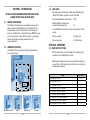
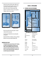
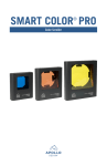
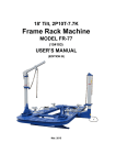
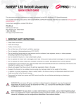
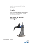
Operating Manual
Automated Gear
Apollo Design Technology, Inc.
4130 Fourier Drive
Fort Wayne, IN 46818
USA
PH: +01(260)497-9191
FX: +01(260)497-9192
www.apollodesign.net
11-25-09
5-6
POWERING UP THE RIGHT ARM
When power is applied to the Right Arm® a homing sequence
will occur. The Right Arm® will slowly move to its calibration point.
After homing is completed, the Right Arm® will move to the home
position at 0% tilt and 50% pan. The Right Arm® will wait in this
position until DMX information is received.
5-7
SELF TEST
Setting a fixture address to 801 or 802 will run the Right Arm® in
a self-test or demonstration mode where it runs through a short
movement routine. 801 runs this test at full speed, 802 runs it at a
slower speed.
IMPORTANT SAFETY NOTICE!
The Right Arm® has the potential of tilting a full 270°.
Attaching accessories, such as gobo rotators, color scrollers,
or gel frames, is the sole responsibility of the user. Be sure to
use and approved safety cables and mounting methods to secure
these devices. Be careful to install safety cables in such a way
as to not inhibit the movement of the Right Arm®.
RIGHT ARM® REPAIRS
l All Right Arms are covered by a 12-month parts and labor warranty. The
warranty covers parts and labor for 12 months and freight for 30 days
after initial purchase. In case of warranty claims, please contact Apollo
Design Technology, Inc. directly at 4130 Fourier Drive, Fort Wayne, IN 46818.
l
Products being returned for warranty repair must display the original serial
number sticker. Removal of the serial number sticker voids the product’s
limited warranty.
l Despite the care taken for the compilation of this book, Apollo Design
Technology, Inc. cannot be held responsible for any damages resulting
from errors that may appear in this book. All efforts have been made to
provide the most accurate, up-to-date instructions and illustrations possible.
l Need assistance? Call Apollo at 800-288-4626 for details.
Right Arm® - Automated Gear
Keep this information handy if requiring assistance.
© Apollo Design Technology Inc. 2007
Serial Number:____________________________________________________
Product covered by US patent 6,953,270
Date Purchased:___________________________________________________
Purchased From: __________________________________________________
15
5-2 CHANNEL ASSIGNMENTS
Option
TABLE OF CONTENTS:
DMX Channels
8 Bit
1 Pan, 2 Tilt
8 Bit + Speed
1 Pan, 2 Tilt, 3 Speed
16 Bit + Speed
1 Pan Coarse, 2 Pan Fine,
3 Tilt Coarse, 4 Tilt Fine, 5 Speed
FORMAT OF SPEED CHANNEL
PAGE NO.
SECTION 1 - INTRODUCTION
1-1 General information
1-2 Compatible fixtures
Modes that have a speed channel (Modes 3-8) use the following format:
SECTION 2 - SPECIFICATIONS
0
Full speed (desk control)
1 – 49% Fast speed to slow speed
50 – 70% Slowest speed
71 – 89% Reset if pan and tilt are at 0 and DMX values are held stationary for 3 seconds or more
90 – 100% Full speed (desk control)
5-3
DATA PASS THROUGH
There are two XLR 5 pin data connectors. One is male for data
input. The other is a female for daisy chaining other DMX fixtures.
The data is a straight pass through and is not buffered or isolated.
If the power is removed from the Right Arm® other DMX devices
will not be affected.
5-4
LOSS OF DMX
If the DMX data to the Right Arm® ceases, the unit will hold the
last position. When the DMX signal is restored normal operation
will resume.
5-5
ACCESSORY OUTPUTS
There are two accessory output ports to connect devices to such as
Smart Color® Scrollers or Smart Move® Rotators.
The total power available for these accessories must not exceed
40 watts. The voltage output is 24 volts DC. The connectors are
XLR 4 pin females. The pin out for the connectors is:
Pin 1 DC common
Pin 2 DMX Data -
Pin 3 DMX Data +
Pin 4 DC 24 volts +
When utilizing the accessory ports be sure to route and secure
cabling in such a way as to not impede the movement of
the Right Arm®.
14
2-1
2-2
2-3 2-4
2-5
4
4
Dimensions, Weight and Performance
Compliance
Electrical
Protocol
Motors
5
6
6
6
6
SECTION 3 - SAFETY
3-1
Safety 6
SECTION 4 - INSTALLATION AND SET-UP
4-1
4-2
4-3
4-4
4-5
4-6
Unpack and Inspect
Installing Connectors Hanging the Right Arm® Attaching a Fixture to the Right Arm® Balancing the Fixture
Data Cable
7
7
8
9
10-11
13
SECTION 5 - OPERATION
5-1
5-2
5-3
5-4
5-5
5-6
Mode Switch Settings
Channel Assignments and Format of Speed Channel
Data Pass Through
Loss Of DMX
Accessory Outputs
Powering Up The Right Arm®
Repairs And Warranty
3
13
14
14
14
14
15
15
SECTION 1 - INTRODUCTION
BE SURE TO READ AND UNDERSTAND EVERYTHING IN THIS
MANUAL BEFORE USING THE RIGHT ARM!
1-1
GENERAL INFORMATION
The Right Arm® is designed to accommodate a wide variety of
small to medium sized lighting fixtures. The Right Arm® has a
patented balance system that eliminates the need for counter
balances. The Right Arm® is controlled from any DMX512 console
and can be operated in 8-bit or 16-bit resolution. Large stepper
motors and high gear ratio drive provides silent and
accurate operation.
1-2
COMPATIBLE FIXTURES
The Right Arm® can accommodate fixtures of approximately
the size shown below:
DATA CABLE
Data cable must be twisted pairs, 120W, shielded E1A485 cable
(Belden 9829, 9842 or equivalent), minimum 22 AWG.
Recommended Maximum cable length:
1000’
Maximum DMX receiving devices
recommended per single line:
32
The last DMX device on the line must be terminated with a 120W
resistor.
Data in connector:
XLR 5 pin male
Data out connector:
XLR 5 pin female
SECTION 5 - OPERATION
36” (914mm)
DEEP
17.3” (440mm)
Maximum Fixture Dimensions
PARs
Video Cameras
4
5-1 MODE SWITCH SETTINGS
With the mode switch set from 0 through 8, the address switch
should be set to the DMX address desired.
Mode switch settings allow the user to choose different ranges of
pan and tilt, 8 or 16 bit resolution, and whether or not a channel to
control speed is required.
Mode
22” (580mm)
Ellipsoidals & Fresnels
4-6
Switch Setting
200° Pan and Tilt, 8 Bit
120° Pan and Tilt, 8 Bit
0
1
90° Pan and Tilt, 8 Bit
200° Pan and Tilt, 8 Bit + Speed
120° Pan and Tilt, 8 Bit + Speed
90° Pan and Tilt, 8 Bit + Speed
340° Pan, 270° Tilt, 16 Bit + Speed
200° Pan and Tilt, 16 Bit + Speed
120° Pan and Tilt, 16 Bit + Speed
2
3
4
5
6
7
8
Projectors
13
Rotate the tilt arm back until the fixture points straight ahead. If
the fixture holds this position, the balance is correct. If not, the
angle of the arm needs to be modified. See the drawings
below of the tilt arm angle. This angle should only require
adjustment on a fixture that is front heavy such as a long throw
ellipsoidal or a fixture with a color changer.
SECTION 2 - SPECIFICATIONS
2-1
DIMENSIONS, WEIGHT AND PERFORMANCE
PIPE OR TRUSS MEMBER
CLAMP
Color
changer
or long
throw.
Tilt arm
angle
adjustment
bolt.
Loosen bolt
and rotate
tilt arm to
center weight
and tighten
bolt.
9.7”
(248mm)
TILT ARM
BALANCE
ADJUSTMENT BOLT
26”
(660mm)
23.3”
(643mm)
AUXILIARY
4-PIN POWER/DMX PORT 1
AND PORT 2
BALANCE
ADJUSTMENT BOLT
Tilt arm angle set to accommodate
a fixture that is front heavy.
Tilt arm angle set at normal position.
Adjust this angle until the fixture holds its position. The balance
should be confirmed in all positions.
Proper balancing of the Right Arm® assures accurate position
during operation.
Extreme fixture imbalances created by 5° or 10° lenses, will require
Right Arm® accessory part number RIGHTARM - 20200.
IMPORTANT SAFETY NOTICE!
The Right Arm® has the potential of tilting a full 270°. Attaching
accessories, such as gobo rotators, color scrollers, or gel
frames, is the sole responsibility of the user. Be sure to use
approved safety cables and mounting methods to secure these
devices. Be careful to install safety cables in such a way as to
not inhibit the movement of the Right Arm®.
12
15”
(381mm)
Overall Dimensions and Key Components
Height: Height, hang below pipe: Width: Depth: 26” (660.4 mm) with clamp
23.3” (591.8 mm)
15” (381 mm)
7” (177.8 mm)
Torque, pan: Torque, tilt: 5 foot-pounds average
10 foot-pounds average
Pan Range:
Pan Speed:
Tilt Range:
Tilt Speed:
340°
180° in 6 seconds
270°
180° in 6 seconds
Right Arm™ Weight: 28 lb (12.7kg) without fixture
Shipping Weight:
34lb (15.4 kg) without fixture
Capacity:
40 lb (18.4 kg)
5
2-2
COMPLIANCE
2-3
ELECTRICAL
This fixture is designed to comply with UL STD 73,
Eighth Edition Motor Operated Appliances.
CE pending
ETL pending
Operating voltage: Fixture power cord rating: Accessory port voltage: Accessory port wattage:
Current required for
Right Arm® alone: Power required for
Right Arm®:
2-4
PROTOCOL
USITT DMX512
Start code: Maximum load: Maximum length of DMX link:
Required control channels: Termination: 2-5
MOTORS
High torque stepper motor
Step Angle: 100-240 VAC + 5%
50/60 Hz (auto select)
15 amps, 250 volts Maximum
24 volts DC
40 watts maximum
.5 amps
TILT
RIGHT ARM® HEIGHT
ADJUSTMENT BOLT
TILT AXIS
50 watts
(00h)
32 fixtures per DMX link
1000 feet
5 (16-bit) or 3 (8-bit)
120W
1.8°, 1/256 microstep
9.3/4”
(250 mm)
9.3/4”
(250 mm)
7”
(178 mm)
FIXTURE
YOKE TILT
AXIS
RIGHT ARM®
TILT AXIS
ETC Source Four Ellipsoidal
ETC Yoke Measures 9 3/4”
Adjust Tilt Arm To 9 3/4”
A moving light is a dangerous piece of equipment. It is for
professional use only.
Attaching accessories, such as gobo rotators, color scrollers,
or gel frames, is the sole responsibility of the user. Use
approved safety cables and mounting methods to secure
these devices.
If the power cable is damaged it must be replaced by the
manufacturer, the service agent or a similarly qualified person
in order to avoid a hazard.
Follow all safety procedures that apply to the lighting fixture to be
attached to the Right Arm®, per the manufacturer’s instructions.
The Right Arm® is designed for use only with fixtures up to 40 lb.
Always ground (earth) the Right Arm®.
6
FIXTURE
YOKE TILT
AXIS
TILT
HEIGHT
ADJUSTMENT BOLT
ETC S4 PAR
ETC Yoke Height 7”
Adjust Tilt Arm To 7”
With the power off, check to see if the height adjustment is correct
by observing if the fixture holds its position after rotating it to point
down as shown below.
If the fixture holds its position proceed to the next step, if not
change the height of the arm and recheck.
SECTION 3 - SAFETY
7”
(178 mm)
Rotate To Face Down
11
5. Connect the lamp power cable to the wire that exits at the
tilt shaft.
6. Secure the cable so that it does not interfere with the
tilt motion.
4-5
BALANCING THE FIXTURE
Always suspend the Right Arm® using the clamp provided. Hang
only on secured truss, pipe, or other structures.
The Right Arm® is not designed to hang vertically.
Always use approved safety cables when hanging the Right Arm®.
Always disconnect the Right Arm® from AC power before service.
Do not expose Right Arm® to dripping or splashing. Objects filled
with liquid shall not be placed on the unit.
Do not put flammable materials on or near the Right Arm®.
SECTION 4 - INSTALLATION AND SET-UP
TILT HEIGHT
ADJUSTMENT
BOLT
TILT ARM
ANGLE
ADJUSTMENT
BOLT
The tilt arm height and the tilt arm angle provide two adjustment
points for balance.
The tilt arm height is adjusted by the tilt height adjustment bolt.
Loosen this bolt to adjust for different height fixtures. The initial
adjustment should be set so the tilt axis of the fixture is at the same
height as the tilt bolt. See examples on the following page:
10
4-1
UNPACK AND INSPECT
Verify that the Right Arm® has arrived complete and undamaged. The shipping container should contain the following items:
1. Right Arm®.
4.Bolt for pipe clamp metric M16x30 hex
2. Right Arm® user’s Manual. head. Includes flat washer and lock washer.
5.Safety cables (2)
3. Pipe clamp.
4-2
INSTALLING CONNECTORS
The Right Arm® comes with two cables for control and two for power.
DMX control in and pass through are provided using five pin XLR
type connectors. One power cable is marked “do no dim” and is used to provide power to the Right Arm® electronics. This cable must be plugged in to a non-dimmed electrical source between 90 volts and 250 volts AC. Plugging this cable in to a dimmed electrical source could damage the Right Arm®.
The second power cable enters the
top of the Right Arm® and passes
through the Right Arm® exiting at the
tilt shaft. This cable is used to power
devices attached to the Right Arm®.
This cable has 16 gauge conductors
and can be plugged into a dimmed
or non-dimmed source to power
fixtures up to 15 amps.
7
Both power cables come with NEMA 5-15
connectors and are wired to European color
code. If the factory installed connectors
must be changed, use the brown wire for
hot, the blue wire for neutral and the green/
yellow wire for ground. Observe proper
grounding on all three power connectors. Both male connectors are
used as the disconnect device and shall remain readily accessible
after the installation of the Right Arm® has been completed.
4-3
ATTACHING A FIXTURE TO THE RIGHT ARM ®
HOLES FOR
ATTACHING
FIXTURE
ON TILT ARM
HANGING THE RIGHT ARM®
The Right Arm® must be securely attached
with the clamp provided. Position the power
box to fit inside of the dotted lines on the
Right Arm® label. Position the clamp with
the pipe bolt facing towards the Right
Arm® rail handles.
The Right Arm® can be hung vertically
with the clamp on top or bottom. The Right
Arm® cannot be hung horizontally with the
clamp on either side.
4-4
Be sure to tighten the bolt that fastens the clamp to the Right
Arm®. The Right Arm® must use the provided safety cable to
prevent the unit from falling in the event that the hanging clamps
or brackets fail.
The provided safety must pass
through the hole on the pan shaft and
also around the pipe or truss. When
attaching the safety cable, keep in
mind the range of motion necessary
for the Right Arm® to operate
properly and adjust the length and/or
placement of the cable accordingly.
8
1. Remove any C-clamps or other hanging brackets from the fixture
to be installed in the Right Arm®.
2.
Bolt the fixture’s yoke to the top of the tilt arm. There are seven
holes in the tilt arm. Use the hole that is closest to the inside
corner of the Right Arm® and allows operation of all parts of the
lighting fixtures. Use lock nuts or lock washers (not provided).
For single hole use 1/2” bolt or double hole use 3/8” bolt.
3. Attach the provided safety cable. This safety should be con
nected to the fixture according to the fixture manufacturer’s
instructions.
4.The safety must also pass through the hole
provided on the tilt shaft. When attaching
the safety cable, keep in mind the range of
motion necessary for the Right Arm® to
operate properly and adjust the length
and/or placement of the cable accordingly.
9