1
Advanced Control Library
for Cortex-M4 Core
User Reference Manual
ACLCM4UG
Rev. 1.1
3/2013
freescale.com
The following revision history table summarizes changes contained in this
document.
Table 0-1. Revision History
Date
Revision
Label
0
03/2013
1.1
Description
Initial release
Support of additional compilers added
Advanced Control Library for Cortex-M4 Core, Rev. 1.1
-2
Freescale Semiconductor
Chapter 1 License Agreement
FREESCALE SEMICONDUCTOR SOFTWARE LICENSE AGREEMENT.
This is a legal agreement between you (either as an individual or as an
authorized representative of your employer) and Freescale Semiconductor, Inc.
("Freescale"). It concerns your rights to use this file and any accompanying
written materials (the "Software"). In consideration for Freescale allowing you
to access the Software, you are agreeing to be bound by the terms of this
Agreement. If you do not agree to all of the terms of this Agreement, do not
download the Software. If you change your mind later, stop using the Software
and delete all copies of the Software in your possession or control. Any copies
of the Software that you have already distributed, where permitted, and do not
destroy will continue to be governed by this Agreement. Your prior use will also
continue to be governed by this Agreement.
OBJECT PROVIDED, OBJECT REDISTRIBUTION LICENSE GRANT.
Freescale grants to you, free of charge, the non-exclusive, non-transferable right
(1) to reproduce the Software, (2) to distribute the Software, and (3) to
sublicense to others the right to use the distributed Software. The Software is
provided to you only in object (machine-readable) form. You may exercise the
rights above only with respect to such object form. You may not translate,
reverse engineer, decompile, or disassemble the Software except to the extent
applicable law specifically prohibits such restriction. In addition, you must
prohibit your sublicensees from doing the same. If you violate any of the terms
or restrictions of this Agreement, Freescale may immediately terminate this
Agreement, and require that you stop using and delete all copies of the Software
in your possession or control.
COPYRIGHT. The Software is licensed to you, not sold. Freescale owns the
Software, and United States copyright laws and international treaty provisions
protect the Software. Therefore, you must treat the Software like any other
copyrighted material (e.g. a book or musical recording). You may not use or
copy the Software for any other purpose than what is described in this
Agreement. Except as expressly provided herein, Freescale does not grant to
you any express or implied rights under any Freescale or third-party patents,
copyrights, trademarks, or trade secrets. Additionally, you must reproduce and
apply any copyright or other proprietary rights notices included on or embedded
in the Software to any copies or derivative works made thereof, in whole or in
part, if any.
SUPPORT. Freescale is NOT obligated to provide any support, upgrades or new
releases of the Software. If you wish, you may contact Freescale and report
problems and provide suggestions regarding the Software. Freescale has no
obligation whatsoever to respond in any way to such a problem report or
Advanced Control Library for Cortex-M4 Core, Rev. 1.1
Freescale Semiconductor
1-3
suggestion. Freescale may make changes to the Software at any time, without any
obligation to notify or provide updated versions of the Software to you.
NO WARRANTY. TO THE MAXIMUM EXTENT PERMITTED BY LAW,
FREESCALE EXPRESSLY DISCLAIMS ANY WARRANTY FOR THE
SOFTWARE. THE SOFTWARE IS PROVIDED "AS IS", WITHOUT
WARRANTY OF ANY KIND, EITHER EXPRESS OR IMPLIED,
INCLUDING, WITHOUT LIMITATION, THE IMPLIED WARRANTIES OF
MERCHANTABILITY, FITNESS FOR A PARTICULAR PURPOSE, OR
NON-INFRINGEMENT. YOU ASSUME THE ENTIRE RISK ARISING OUT
OF THE USE OR PERFORMANCE OF THE SOFTWARE, OR ANY
SYSTEMS YOU DESIGN USING THE SOFTWARE (IF ANY). NOTHING IN
THIS AGREEMENT MAY BE CONSTRUED AS A WARRANTY OR
REPRESENTATION BY FREESCALE THAT THE SOFTWARE OR ANY
DERIVATIVE WORK DEVELOPED WITH OR INCORPORATING THE
SOFTWARE WILL BE FREE FROM INFRINGEMENT OF THE
INTELLECTUAL PROPERTY RIGHTS OF THIRD PARTIES.
INDEMNITY. You agree to fully defend and indemnify Freescale from any and
all claims, liabilities, and costs (including reasonable attorney's fees) related to
(1) your use (including your sublicensee's use, if permitted) of the Software or (2)
your violation of the terms and conditions of this Agreement.
LIMITATION OF LIABILITY. IN NO EVENT WILL FREESCALE BE
LIABLE, WHETHER IN CONTRACT, TORT, OR OTHERWISE, FOR ANY
INCIDENTAL, SPECIAL, INDIRECT, CONSEQUENTIAL OR PUNITIVE
DAMAGES, INCLUDING, BUT NOT LIMITED TO, DAMAGES FOR ANY
LOSS OF USE, LOSS OF TIME, INCONVENIENCE, COMMERCIAL LOSS,
OR LOST PROFITS, SAVINGS, OR REVENUES TO THE FULL EXTENT
SUCH MAY BE DISCLAIMED BY LAW.
COMPLIANCE WITH LAWS; EXPORT RESTRICTIONS. You must use the
Software in accordance with all applicable U.S. laws, regulations and statutes.
You agree that neither you nor your licensees (if any) intend to or will, directly or
indirectly, export or transmit the Software to any country in violation of U.S.
export restrictions.
GOVERNMENT USE. Use of the Software and any corresponding
documentation, if any, is provided with RESTRICTED RIGHTS. Use,
duplication or disclosure by the Government is subject to restrictions as set forth
in subparagraph (c)(1)(ii) of The Rights in Technical Data and Computer
Software clause at DFARS 252.227-7013 or subparagraphs (c)(l) and (2) of the
Commercial Computer Software--Restricted Rights at 48 CFR 52.227-19, as
applicable. Manufacturer is Freescale Semiconductor, Inc., 6501 William
Cannon Drive West, Austin, TX, 78735.
HIGH RISK ACTIVITIES. You acknowledge that the Software is not fault
tolerant and is not designed, manufactured or intended by Freescale for
Advanced Control Library for Cortex-M4 Core, Rev. 1.1
1-4
Freescale Semiconductor
incorporation into products intended for use or resale in on-line control
equipment in hazardous, dangerous to life or potentially life-threatening
environments requiring fail-safe performance, such as in the operation of nuclear
facilities, aircraft navigation or communication systems, air traffic control, direct
life support machines or weapons systems, in which the failure of products could
lead directly to death, personal injury or severe physical or environmental
damage ("High Risk Activities"). You specifically represent and warrant that you
will not use the Software or any derivative work of the Software for High Risk
Activities.
CHOICE OF LAW; VENUE; LIMITATIONS. You agree that the statutes and
laws of the United States and the State of Texas, USA, without regard to conflicts
of laws principles, will apply to all matters relating to this Agreement or the
Software, and you agree that any litigation will be subject to the exclusive
jurisdiction of the state or federal courts in Texas, USA. You agree that regardless
of any statute or law to the contrary, any claim or cause of action arising out of or
related to this Agreement or the Software must be filed within one (1) year after
such claim or cause of action arose or be forever barred.
PRODUCT LABELING. You are not authorized to use any Freescale trademarks,
brand names, or logos.
ENTIRE AGREEMENT. This Agreement constitutes the entire agreement
between you and Freescale regarding the subject matter of this Agreement, and
supersedes all prior communications, negotiations, understandings, agreements
or representations, either written or oral, if any. This Agreement may only be
amended in written form, executed by you and Freescale.
SEVERABILITY. If any provision of this Agreement is held for any reason to be
invalid or unenforceable, then the remaining provisions of this Agreement will be
unimpaired and, unless a modification or replacement of the invalid or
unenforceable provision is further held to deprive you or Freescale of a material
benefit, in which case the Agreement will immediately terminate, the invalid or
unenforceable provision will be replaced with a provision that is valid and
enforceable and that comes closest to the intention underlying the invalid or
unenforceable provision.
NO WAIVER. The waiver by Freescale of any breach of any provision of this
Agreement will not operate or be construed as a waiver of any other or a
subsequent breach of the same or a different provision.
Advanced Control Library for Cortex-M4 Core, Rev. 1.1
Freescale Semiconductor
1-5
Chapter 2 INTRODUCTION
2.1
Overview
This Reference Manual describes Advanced Control Library for Cortex-M4
Core for Freescale 32-bit ARM® Cortex™-M4 based Kinetis family of
microcontrollers. This library contains optimized functions for the Kinetis
family of microcontrollers. The library is supplied in a binary form, which is
unique for its ease of integration with user applications. The Set of General
Math and Motor Control Functions for Cortex-M4 Core must be included in the
application project for correct functionality of the Advanced Motor Control
Library.
2.2
References
[1] MCLIBCORETXM4UG - Set of General Math and Motor Control Functions
for Cortex M4 Core, User Reference Manual, Freescale Semiconductor, 20122
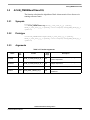
2.3
Supported compilers
Advanced Control Library for Cortex-M4 Core (ACLIB) is written in C
language using some of the compiller’s intrinsics functions in order to directly
utilize specific core instructions. The library was built and tested using
following compilers:
1. IAR Embedded Workbench® for ARM v. 4.40.2
2. CodeWarrior for MCU, version 10.3, GCC build tools
3. KeilVision V4.60.0.0
The library is delivered in the library module Cortex_M4_XX.a, together with
Set of General Math and Motor Control Functions for Cortex-M4 Core. The XX
denotes the particular compiller (CW, IAR, KEIL). The interfaces to the
algorithms included in this library have been combined into a single public
interface include file, aclib.h. This was done to simplify the number of files
required for inclusion by application programs. Refer to the specific algorithm
sections of this document for details on the software application programming
interface (API), definitions, and functionality provided for the individual
algorithms.
2.4
Installation
The ACLIB is delivered as a single executable file, with Set of General Math
and Motor Control Functions for Cortex-M4 Core. To install the ACLIB on a
user computer, run the installation file CORTEX_M4_FSLESL.exe and follow
Advanced Control Library for Cortex-M4 Core, Rev. 1.1
Freescale Semiconductor
2-6
Library integration into the software project
the steps that are listed in the user’s manual dedicated to Set of General Math and
Motor Control Functions for Cortex-M4 Core [1].
2.5
Library integration into the software project
The procedure to include the library in the software project is described
separately for each supported compiler in the user’s manual dedicated to Set of
General Math and Motor Control Functions for Cortex-M4 Core [1]. Special
attention needs to be paid when this library is included in the CodeWarrior 10.3
project with ARM® GCC build tools used.
2
2.6
API definition
The description of each function described in this Advanced Control Library for
Cortex-M4 Core user reference manual consists of a number of subsections:
Synopsis
This subsection gives the header files that should be included within
a source file that references the function or macro. It also shows an
appropriate declaration for the function or for a function that can be
substituted by a macro. This declaration is not included in your
program; only the header file(s) should be included.
Prototype
This subsection shows the original function prototype declaration
with all its arguments.
Arguments
This optional subsection describes input arguments to a function or
macro.
Description
This subsection is a description of the function or macro. It explains
algorithms being used by functions or macros.
Return
This optional subsection describes the return value, if any, of the
function or macro.
Range issues
This optional subsection specifies the ranges of input variables.
Special issues
This optional subsection specifies special assumptions that are
mandatory for correct function calculation; for example, saturation,
rounding, and so on.
Implementation
This optional subsection specifies whether a call of the function
generates a library function call or a macro expansion.
Advanced Control Library for Cortex-M4 Core, Rev. 1.1
Freescale Semiconductor
2-7
Data types
This subsection also consists of one or more examples of the use of
the function. The examples are often fragments of code—not
completed programs—for illustration purposes.
See also
This optional subsection provides a list of related functions or macros.
Performance
This section specifies the actual requirements of the function or macro
in terms of required code memory, data memory, and number of clock
cycles to execute.
2.7
Data types
The 32-bit Cortex-M4 core supports two types of two’s-complement data
formats:
• Signed integer
• Unsigned integer
The signed and unsigned integer data types are useful for general-purpose
computation; they are familiar to the microprocessor and microcontroller
programmers. The calculations performed in the library functions utilize
fractional data types:
• Signed fractional
• Unsigned fractional
Fractional data types allow powerful numeric and digital-signal-processing
algorithms to be implemented. Even though calulations in these fractional data
types are not directly supported by Cortex-M4 core architecture, it is not difficult
to emulate the calculations by software, and therefore benefit from using the
fractional arithmetic.
2.7.1
Signed integer (SI)
This format is used for processing data as integers. In this format, the N-bit
operand is represented using the N.0 format (N integer bits). The signed integer
numbers lie in the following range:
– 2 N – 1 SI 2 N – 1 – 1
Eqn. 2-1
This data format is available for bytes, words, and longs. The most negative
signed word that can be represented is –32,768 ($8000), and the most negative
signed long word is –2,147,483,648 ($80000000).
The most positive signed word is 32,767 ($7FFF), and the most positive signed
long word is 2,147,483,647 ($7FFFFFFF).
Advanced Control Library for Cortex-M4 Core, Rev. 1.1
2-8
Freescale Semiconductor
Data types
2.7.2
Unsigned integer (UI)
The unsigned integer numbers are positive only, and they have nearly twice the
magnitude of a signed number of the same size. The unsigned integer numbers lie
in the following range:
0 UI 2 N – 1 – 1
Eqn. 2-2
The binary word is interpreted as having a binary point immediately to the right
of the integer’s least significant bit. This data format is available for bytes, words,
and long words. The most positive 16-bit, unsigned integer is 65,535 ($FFFF),
and the most positive 32-bit, unsigned integer is 4,294,967,295 ($FFFFFFFF).
The smallest unsigned integer number is zero ($0000), regardless of size.
2.7.3
Signed fractional (SF)
In this format, the N-bit operand is represented using the 1.[N–1] format (one sign
bit, N–1 fractional bits). The signed fractional numbers lie in the following range:
– 1.0 SF 1.0 – 2 – N – 1
Eqn. 2-3
This data format is available for words and long words. For both word and
long-word signed fractions, the most negative number that can be represented
is –1.0; its internal representation is $8000 (word) or $80000000 (long word).
The most positive word is $7FFF (1.0 – 2–15); its most positive long word
is $7FFFFFFF (1.0 – 2–31).
2.7.4
Unsigned fractional (UF)
The unsigned fractional numbers can only be positive, and they have nearly twice
the magnitude of a signed number with the same number of bits. The unsigned
fractional numbers lie in the following range:
0.0 UF 2.0 – 2 – N – 1
Eqn. 2-4
The binary word is interpreted as having a binary point after the MSB. This data
format is available for words and longs. The most positive 16-bit, unsigned
number is $FFFF, or {1.0 + (1.0 – 2–[N–1])} = 1.99997. The smallest unsigned
fractional number is zero ($0000).
Advanced Control Library for Cortex-M4 Core, Rev. 1.1
Freescale Semiconductor
2-9
User common types
2.8
User common types
Table 2-1. User-defined typedefs in MCF51_types.h
Mnemonics
Size — bits
Description
Word8
8
To represent 8-bit signed variable/value.
UWord8
8
To represent 8-bit unsigned variable/value.
Word16
16
To represent 16-bit signed variable/value.
UWord16
16
To represent 16-bit unsigned variable/value.
Word32
32
To represent 32-bit signed variable/value.
UWord32
32
To represent 32-bit unsigned variable/value.
Int8
8
To represent 8-bit signed variable/value.
UInt8
8
To represent 8-bit unsigned variable/value.
Int16
16
To represent 16-bit signed variable/value.
UInt16
16
To represent 16-bit unsigned variable/value.
Int32
32
To represent 32-bit signed variable/value.
UInt32
32
To represent 32-bit unsigned variable/value.
Frac16
16
To represent 16-bit signed variable/value.
Frac32
32
To represent 32-bit signed variable/value.
NULL
constant
Represents NULL pointer.
bool
16
Boolean variable.
false
constant
Represents false value.
true
constant
Represents true value.
FRAC16()
macro
Transforms float value from <–1, 1) range into fractional
representation <–32768, 32767>.
FRAC32()
macro
Transforms float value from <–1, 1) range into fractional
representation <–2147483648, 2147483648>.
Advanced Control Library for Cortex-M4 Core, Rev. 1.1
2-10
Freescale Semiconductor
Code size and execution time data
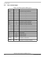
Table 2-2. User-Defined Typedefs in mclib_types.h
Name
2.9
Structure members
Description
MCLIB_3_COOR_SYST_T
Frac32 f32A
Frac32 f32B
Frac32 f32C
three phase system
MCLIB_2_COOR_SYST_T
Frac32 f32A
Frac32 f32B
two phase system
MCLIB_2_COOR_SYST_ALPHA_BETA_T
Frac32 f32Alpha
Frac32 f32Beta
two phase system — alpha/beta
MCLIB_2_COOR_SYST_D_Q_T
Frac32 f32D
Frac32 f32Q
two phase system — generic DQ
MCLIB_ANGLE_T
Frac32 f32Sin
Frac32 f32Cos
two phase system — sine and
cosine components
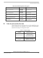
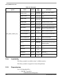
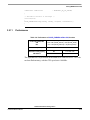
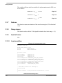
Code size and execution time data
This document provides, for each function, the size of the compiled binary code
and the execution time of the algorithms for each compiler. The following table
summarizes the settings of each supported compiler.
2
Table 2-3. Compilers settings
Copolymer
Optimization options
IAR Embedded Workbench
Optimization level “High”
Optimize for “Speed”
“No size constraints” checked
All transformations enabled
CodeWarrior for MCU
Optimize most (-O3)
Keil Vision
Optimization: “Level 3(-O3)”
“Optimize for Time” checked
Advanced Control Library for Cortex-M4 Core, Rev. 1.1
Freescale Semiconductor
2-11
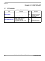
API Summary
Chapter 3 FUNCTION API
3.1
API Summary
Table 3-1. API functions summary
Name
Arguments
ACLIB_TrackObsrv
Frac32 f32ThetaErr
ACLIB_TRACK_OBSRV_T * const pudtCtrl
ACLIB_PMSMBemfObsrvDQ
MCLIB_2_COOR_SYST_D_Q_T *pudtIdq
MCLIB_2_COOR_SYST_D_Q_T
*pudtUdq,Frac32 f32Speed
ACLIB_BEMF_OBSRV_DQ_T * const
pudtCtrl
Output
Description
void
This function calculates the
tracking observer for
determination angular speed
and position of input error
functional signal.
void
The function calculates the
algorithm of back
electro-motive force observer
in rotating reference frame.
Advanced Control Library for Cortex-M4 Core, Rev. 1.1
3-12
Freescale Semiconductor
ACLIB_PMSMBemfObsrvDQ
3.2
ACLIB_PMSMBemfObsrvDQ
The function calculates the algorithm of back electro-motive force observer in
rotating reference frame.
3.2.1
Synopsis
#include ”aclib.h”
void ACLIB_PMSMBemfObsrvDQ(MCLIB_2_COOR_SYST_D_Q_T *pudtIDQ,
MCLIB_2_COOR_SYST_D_Q_T *pudtUDQ, Frac32 f32Speed, ACLIB_BEMF_OBSRV_DQ_T
*pudtCtrl)
3.2.2
Prototype
void ACLIB_PMSMBemfObsrvDQFC(MCLIB_2_COOR_SYST_D_Q_T *pudtIDQ,
MCLIB_2_COOR_SYST_D_Q_T *pudtUDQ, Frac32 f32Speed, ACLIB_BEMF_OBSRV_DQ_T
*pudtCtrl)
3.2.3
Arguments
Table 3-2. Function arguments
Name
In/
Out
Format
Valid
range
Description
*pudtIDQ
in
MCLIB_2_COOR_SYST_D_Q_T
N/A
Pointer to structure which contain input signal of d/q
current components.
*pudtUDQ
in
MCLIB_2_COOR_SYST_D_Q_T
N/A
Pointer to structure which contain input signal of d/q
voltage components.
f32Speed
in/out
Frac32
N/A
Fraction value of electrical speed.
*pudtCtrl
in/out
ACLIB_BEMF_OBSRV_DQ_T
N/A
Pointer to an observer structure, which contains
coefficients.
Advanced Control Library, Rev. 2
Freescale Semiconductor
3-13
ACLIB_PMSMBemfObsrvDQ
Table 3-3. User types
Typedef
Name
ACLIB_BEMF_OBSRV_DQ_T
3.2.4
Format
Valid
range
Description
udtEObsrv.f32D
Frac32
0x80000000... Estimated back-EMF voltage in
0x7FFFFFFF d-axis.
udtEObsrv.f32Q
Frac32
0x80000000... Estimated back-EMF voltage in
0x7FFFFFFF q-axis.
udtIObsrv.f32D
Frac32
0x80000000...
Estimated current in d-axis.
0x7FFFFFFF
udtIObsrv.f32Q
Frac32
0x80000000...
Estimated current in q-axis.
0x7FFFFFFF
udtCtrl.f32ID_1
Frac32
0x80000000... State variable in alpha part of the
0x7FFFFFFF observer; integral part at step k-1;
udtCtrl.f32IQ_1
Frac32
0x80000000... State variable in beta part of the
0x7FFFFFFF observer; integral part at step k-1;
udtCtrl.f16PropScaled
Frac16
udtCtrl.i16PropShift
Word16
udtCtrl.f16IntegScaled
Frac16
$8000...
$7FFF
udtCtrl.i16IntegShift
Word16
-F...F
f32Error
Frac32
f16IScaled
Frac16
$8000...
$7FFF
Scaling coefficient for current
f16UScaled
Frac16
$8000...
$7FFF
Scaling coefficient for voltage
f16WIScaled
Frac16
$8000...
$7FFF
Scaling coefficient for angular
speed WI FRAC
f16EScaled
Frac16
$8000...
$7FFF
Scaling coefficient for back-emf
$8000...
$7FFF
-F...F
Observer proportional gain.
Observer proportional gain shift.
Observer integral gain.
Observer integral gain shift.
Estimated phase error between real
0x80000000...
d/q frame system and estimated d/q
0x7FFFFFFF
reference system.
I FRAC
U FRAC
E FRAC
Availability
This library module is available in the C-callable interface.
This library module is targeted for Cortex-M4 platforms.
3.2.5
Dependencies
List of all dependent files:
• SWLIBS_Typedefs.h
Advanced Control Library, Rev. 2
3-14
Freescale Semiconductor
ACLIB_PMSMBemfObsrvDQ
•
•
•
•
•
•
3.2.6
SWLIBS_Defines.h
SWLIBS_Inlines.h
intrinsic.h
Cortex_M4_IAR.a library
ACLIB_PMSMBemfObsrvDQ.h
aclib.h
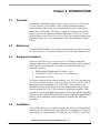
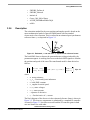
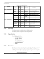
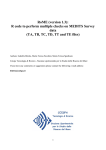
Description
The estimation method for the rotor position and angular speed is based on the
motor mathematical model of interior PMSM motor with an extended
electro-motive force function. This is realized in an estimated quasi synchronous
reference frame as depicted in Figure 3-1.
3
Figure 3-1. Estimated and real rotor dq synchronous reference frames
The back-EMF observer detects the generated motor voltages induced by the
permanent magnets. A tracking observer uses the back-EMF signals to calculate
the position and speed of the rotor. The transformed model is then derived as
follows:
3
u
u
where
•
•
•
•
•
•
•
•
=
R S + sL D – r L Q
r LQ
i
R S + sL D i
+ L e i D – i Q' + k e e
– sin error
cos error
Eqn. 3-1
3
stator resistance
L D L Q - D-axis and Q-axis inductance
k e back-EMF constant
e angular electrical speed
u D u Q stator voltages
i D i Q stator currents
s operator of derivative
i q' - first derivative of i q current
Rs
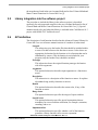
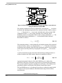
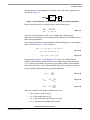
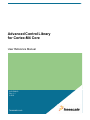
The block diagram of the observer in the estimated reference frame is shown in
Figure 3-2. The observer compensator is substituted by a standard PI controller.
As noted in Figure 3-2, the observer model and the PI controller gains in both
axes are identical to each other.
3
Advanced Control Library, Rev. 2
Freescale Semiconductor
3-15
ACLIB_PMSMBemfObsrvDQ
Figure 3-2. Block diagram of proposed Luenberger type stator current observer
acting as state filter for back-EMF.
The position estimation can now be performed by extracting the error term from
the model and adjusting the position of the estimated reference frame to achieve
error = 0 . Because the error term is only included in the saliency-based EMF
component of both u u axis voltage equations, the Luenberger based
disturbance observer is designed to observe these voltage components u u . The
position displacement information error is then obtained from estimated
back-EMFs as follows:
3
–u
error = atan --------
u
Eqn. 3-2
The estimated position ̂ r can be obtained by driving the position of the estimated
reference frame to achieve zero displacement error = 0 . The phase locked loop
mechanism can be adopted, where the loop compensator ensures correct tracking
of the actual rotor flux position by keeping the error signal error to be zeroed,
error = 0 .
3
A perfect match between the actual and estimated motor model parameters is
assumed, and the back-EMF transfer function is simplified as follows
3
Fc s
Eˆ s = – E s ----------------------------------------sL D + R S + F C s
Eqn. 3-3
Appropriate dynamic behavior of the back EMFobserver is achieved by
placement of the poles of the stator current observer characteristic polynomial.
This general method is based on matching the coefficients of the characteristic
polynomial with the coefficients of the general second-order system.
3
The back EMFobserver is a Luenberger type observer with motor model which
is realized in fixed point arithmetic and transformed using backward Euler
transformation.
3
Advanced Control Library, Rev. 2
3-16
Freescale Semiconductor
ACLIB_PMSMBemfObsrvDQ
i FRFAC k = U FRAC u FRAC k + E FRAC e FRAC k + WI FRAC eFRAC k i' FRAC k
+ I FRAC i FRAC k – 1
Eqn.
3-4
where
• iFRFAC k = i i is fractional representation of stator current vector
• u FRAC k = u u is fractional representation of stator voltage vector
• e FRAC k = e e is fractional representation of stator back-emf voltage
vector
• i' FRFAC k = i – i is fractional representation of complementary stator
current vector
• FRFAC k is fractional representation of angular speed
Scaling coefficients relating to maximal values are expressed as
where
•
•
•
•
•
T S
U MAX
- ------------U FRAC = --------------------------L D + T S R S I MAX
Eqn. 3-5
T S
E MAX
- -----------E FRAC = --------------------------L D + T S R S I MAX
Eqn. 3-6
L Q T S
- MAX
WI FRAC = --------------------------L D + T S R S
Eqn. 3-7
LD
I FRAC = --------------------------L D + T S R S
Eqn. 3-8
T S
sampling time in [sec]
I MAX maximal peak current in [A]
E MAX maximal peak back-emf voltage in [V]
U MAX maximal peak stator voltage in [V]
MAX maximal angular speed in [rad/sec]
If a Luenberger type stator current observer is properly designed in the stationary
reference frame, the back-EMF can be estimated as a disturbance, produced by
the observer controller. This is only valid however if the back-EMF term is not
included in the observer model. The observer is actually a closed loop current
observer so it acts as a state filter for the back-EMF term.
The estimate of extended EMF term can be derived from Equation 3-3 as follows:
ˆ
E s
sK P + K I
– --------------- = ----------------------------------------------------2
E s
s L D + sR S + sK P + K I
Eqn. 3-9
Advanced Control Library, Rev. 2
Freescale Semiconductor
3-17
ACLIB_PMSMBemfObsrvDQ
The observer controller can be designed by comparing the closed loop
characteristic polynomial with that of a standard second order system as:
KP + RS
K
2
- s + ------I = s 2 + 2 0 s + 20
s + -----------------LD
LD
Eqn. 3-10
where
• 0 is the natural frequency of the closed loop system (loop bandwith)
• is the loop attenuation.
3.2.7
Returns
The function returns a phase error between the real rotating reference frame and
the estimated one.
3.2.8
Range issues
The function works with the 32-bit signed fractional values in the range <-1,1).
3.2.9
Special issues
N/A.
3.2.10
Implementation
Example 3-1. Implementation Code
#include "gflib.h"
#include "mclib.h"
#include "aclib.h"
MCLIB_2_COOR_SYST_D_Q_T
ACLIB_BEMF_OBSRV_DQ_T
Frac32
mcIdq,mcUdq;
acBemfObsrv;
f32Speed;
void main (void)
{
acBemfObsrv.udtIObsrv.f32D = FRAC32(0.0);
acBemfObsrv.udtIObsrv.f32Q = FRAC32(0.0);
acBemfObsrv.udtEObsrv.f32D = FRAC32(0.0);
acBemfObsrv.udtEObsrv.f32Q = FRAC32(0.0);
acBemfObsrv.udtCtrl.f32ID_1= FRAC32(0.0);
acBemfObsrv.udtCtrl.f32IQ_1= FRAC32(0.0);
acBemfObsrv.udtCtrl.f16PropScaled= BEMFOBSRV_DQ_PROP_GAIN_SCALED;
acBemfObsrv.udtCtrl.i16PropShift= BEMFOBSRV_DQ_PROP_GAIN_SHIFT;
acBemfObsrv.udtCtrl.f16IntegScaled= BEMFOBSRV_DQ_INTEG_GAIN_SCALED;
acBemfObsrv.udtCtrl.i16IntegShift
= BEMFOBSRV_DQ_INTEG_GAIN_SHIFT;
acBemfObsrv.f16IScaled
= BEMFOBSRV_DQ_I_SCALED;
acBemfObsrv.f16UScaled
= BEMFOBSRV_DQ_U_SCALED;
acBemfObsrv.f16EScaled
= BEMFOBSRV_DQ_E_SCALED;
Advanced Control Library, Rev. 2
3-18
Freescale Semiconductor
ACLIB_PMSMBemfObsrvDQ
acBemfObsrv.f16WIScaled
= BEMFOBSRV_DQ_WI_SCALED;
}
/* Periodical function or interrupt */
void ISR(void)
{
ACLIB_PMSMBemfObsrvDQ(&mcIdq, &mcUdq, f32Speed, &acBemfObsrv);
}
3.2.11
Performance
Table 3-4. Performance of ACLIB_PMSMBemfObsrvDQ function
Code size (words) IAR
CW
Keil
584 + 196 (GFLIB_AtanYX) + 220 (GFLIB_ATAN)
648 + 364 (GFLIB_AtanYX) + 220 (GFLIB_ATAN)
574 + 264 (GFLIB_AtanYX) + 78 (GFLIB_ATAN)
Data size (words)
0
Execution clock [cycles]
IAR/CW/Keil
Min
172 / 209 / 188
Max
290 / 501 / 298
The algorithm test was performed on the MK40X265VMD100 device. The code
ran from flash memory, with the CPU speed set to 100 MHz.
Advanced Control Library, Rev. 2
Freescale Semiconductor
3-19
ACLIB_PMSMBemfObsrvDQ
Advanced Control Library, Rev. 2
3-20
Freescale Semiconductor
ACLIB_TrackObsrv
3.3
ACLIB_TrackObsrv
The function calculates tracking observer for determination angular speed and
position of input error functional signal.
3.3.1
Synopsis
#include”aclib.h”
Frac32 ACLIB_TrackObsrv(Frac32 f32Error, ACLIB_TRACK_OBSRV_T *pudtCtrl)
3.3.2
Prototype
Frac32 ACLIB_TrackObsrvFC(Frac32 f32Error, ACLIB_TRACK_OBSRV_T
*pudtCtrl)
3.3.3
Arguments
Table 3-5. Function arguments
Name
In/
Out
Format
Valid range
0x80000000...
0x7FFFFFFF
f32Error
in
Frac32
*pudtCtrl
in/out
ACLIB_TRACK_OBSRV_T
N/A
Description
input signal representing phase error of
system to be estimated
pointer to a tracking observer structure
ACLIB_TRACK_OBSRV_T, which contains
algorithm coefficients
Advanced Control Library, Rev. 2
Freescale Semiconductor
3-21
ACLIB_TrackObsrv
Table 3-6. User type definitions
Typedef
ACLIB_TRACK_OBSRV_T
ACLIB_TRACK_OBSRV_T
3.3.4
In/
Out
Format
Valid range
f32Theta
in/out
Frac32
0x80000000...
0x7FFFFFFF
Estimated position as output of the
second numerical integrator
f32Speed
in/out
Frac32
0x80000000...
0x7FFFFFFF
Estimated speed as output of the
first numerical integrator
f32I_1
in/out
Frac32
0x80000000...
0x7FFFFFFF
State variable in controller part of the
observer; integral part at step k-1
f16PropScale
in
Frac16
$8000...
$7FFF
i16PropShift
in
Word16
-F...F
f16IntegScale
in
Frac16
$8000...
$7FFF
i16IntegShift
in
Word16
-F...F
f16ThScaled
in
Frac16
$8000...
$7FFF
i16ThShift
in
Word16
-F...F
Name
Description
Obsrever proportional gain
Obsrever proportional gain shift
Obsrever integral gain
Obsrever integral gain shift
Scaling coefficient for output
integrator of position
Scaling coefficient shift for output
integrator of position
Availability
This library module is available in the C-callable interface.
This library module is targeted for Cortex-M4 platforms.
3.3.5
Dependencies
List of all dependent files:
• SWLIBS_Typedefs.h
• SWLIBS_Defines.h
• SWLIBS_Inlines.h
• Cortex_M4_IAR.a library
• ACLIB_TrackObsrv.h
• aclib.h
3.3.6
Description
This function calculates the tracking observer algorithm where the phase locked
loop mechanism is adopted. It is recommended to call this function at every
sampling period. It requires a single input argument as phase error. Such phase
Advanced Control Library, Rev. 2
3-22
Freescale Semiconductor
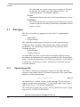
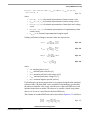
ACLIB_TrackObsrv
tracking observer, with standard PI controller used as the loop compensator, is
depicted in Figure 3-3.
Figure 3-3. Block diagram of proposed PLL scheme for position estimation
Depicted tracking observer structure has the transfer function as
sK p + K i
̂ s
---------- = ------------------------------2
s
s + sK p + K i
Eqn. 3-11
where the controller gains K p and K i are calculated by comparing the
characteristic polynomial of the resulting transfer function to a standard second
order system polynomial.
The essential equations for implementation of the tracking observer, according to
block scheme in Figure 3-3, are as follows:
k = K p e k + T S K i e k + I k – 1
I k = T S K i e k + I k – 1
k = k – 1 + T S k
Eqn. 3-12
Eqn. 3-13
In equations Equation 3-12 and Equation 3-13, there are coefficients and
quantities that might be greater than one (for example, the actual rotor speed
k ) or that are too small to be precisely represented within 16-bit fractional
value. Due to this fact, a special transformation has to be carried out in order to
be successfully implemented using fractional arithmetic.
Kp
K pFRAC = ------------ MAX
Eqn. 3-14
Ki
K iFRAC = T S ------------ MAX
Eqn. 3-15
MAX
T hFRAC = T S ------------- MAX
Eqn. 3-16
where the variables of the angle tracking observer are
• e(k) is observer error in step k,
• TS is the sampling period [s],
• k is the actual rotor speed [rad/s] in step k,
• k is the actual rotor angle [rad] in step k.
Advanced Control Library, Rev. 2
Freescale Semiconductor
3-23
ACLIB_TrackObsrv
The scaled coefficients which are suitable for implementation on the DSP core
are as follows:
– i16KPShift
Eqn. 3-17
f16KIScaled = K iFRAC 2
– i16KIShift
Eqn. 3-18
f16ThScaled = T hFRAC 2
– i16ThShift
Eqn. 3-19
f16KPScaled = K pFRAC 2
3.3.7
Returns
The function returns an estimation of the actual rotor angle as 32-bit fractional
value.
3.3.8
Range issues
The function works with the 32-bit signed fractional values in the range <-1,1).
3.3.9
Special issues
N/A.
3.3.10
Implementation
Example 3-2. Implementation Code
#include "aclib.h"
ACLIB_TRACK_OBSRV_T acTo;
Frac32
f32ThetaError;
Frac32
f32PositionEstim;
void main (void)
{
acTo.f32Theta
= FRAC32(0.0);
acTo.f32Speed
= FRAC32(0.0);
acTo.f32I_1
= FRAC32(0.0);
acTo.f16PropScale= TRACKOBSRV_PROP_GAIN_SCALED;
acTo.i16PropShift= TRACKOBSRV_PROP_GAIN_SHIFT;
acTo.f16IntegScale= TRACKOBSRV_INTEG_GAIN_SCALED;
acTo.i16IntegShift= TRACKOBSRV_INTEG_GAIN_SHIFT;
acTo.f16ThScaled= TRACKOBSRV_TH_SCALED;
acTo.i16ThShift = TRACKOBSRV_TH_SHIFT;
}
/* Periodical function or interrupt */
void ISR(void)
{
f32PositionEstim = ACLIB_TrackObsrv(f32ThetaError, &acTo);
}
Advanced Control Library, Rev. 2
3-24
Freescale Semiconductor
ACLIB_TrackObsrv
3.3.11
Performance
Table 3-7. Performance of ACLIB_TrackObsrv function
Code size [bytes] IAR/CW/Keil
194 / 228 / 184
Data size [bytes]
0
Execution clock [cycles]
IAR/CW/Keil
Min
49 / 57 / 52
Max
49 / 57 / 52
The algorithm test was performed on the MK40X265VMD100 device. The code
ran from flash memory, with the CPU speed set to 100 MHz.
Advanced Control Library, Rev. 2
Freescale Semiconductor
3-25
ACLIB_TrackObsrv
Advanced Control Library, Rev. 2
3-26
Freescale Semiconductor
How to Reach Us:
Home Page:
www.freescale.com
E-mail:
[email protected]
USA/Europe or Locations Not Listed:
Freescale Semiconductor
Technical Information Center, CH370
1300 N. Alma School Road
Chandler, Arizona 85224
+1-800-521-6274 or +1-480-768-2130
[email protected]
Europe, Middle East, and Africa:
Freescale Halbleiter Deutschland GmbH
Technical Information Center
Schatzbogen 7
81829 Muenchen, Germany
+44 1296 380 456 (English)
+46 8 52200080 (English)
+49 89 92103 559 (German)
+33 1 69 35 48 48 (French)
[email protected]
Japan:
Freescale Semiconductor Japan Ltd.
Headquarters
ARCO Tower 15F
1-8-1, Shimo-Meguro, Meguro-ku,
Tokyo 153-0064
Japan
0120 191014 or +81 3 5437 9125
[email protected]
Asia/Pacific:
Freescale Semiconductor Hong Kong Ltd.
Technical Information Center
2 Dai King Street
Tai Po Industrial Estate
Tai Po, N.T., Hong Kong
+800 2666 8080
[email protected]
For Literature Requests Only:
Freescale Semiconductor Literature Distribution Center
P.O. Box 5405
Denver, Colorado 80217
1-800-441-2447 or 303-675-2140
Fax: 303-675-2150
[email protected]
ACLCM4UG
Rev. 1.1, 3/2013
RoHS-compliant and/or Pb-free versions of Freescale products have the functionality
and electrical characteristics of their non-RoHS-compliant and/or non-Pb-free
counterparts. For further information, see http://www.freescale.com or contact your
Freescale sales representative.
For information on Freescale’s Environmental Products program, go to
http://www.freescale.com/epp.
Information in this document is provided solely to enable system and software
implementers to use Freescale Semiconductor products. There are no express or
implied copyright licenses granted hereunder to design or fabricate any integrated
circuits or integrated circuits based on the information in this document.
Freescale Semiconductor reserves the right to make changes without further notice to
any products herein. Freescale Semiconductor makes no warranty, representation or
guarantee regarding the suitability of its products for any particular purpose, nor does
Freescale Semiconductor assume any liability arising out of the application or use of any
product or circuit, and specifically disclaims any and all liability, including without
limitation consequential or incidental damages. “Typical” parameters that may be
provided in Freescale Semiconductor data sheets and/or specifications can and do vary
in different applications and actual performance may vary over time. All operating
parameters, including “Typicals”, must be validated for each customer application by
customer’s technical experts. Freescale Semiconductor does not convey any license
under its patent rights nor the rights of others. Freescale Semiconductor products are
not designed, intended, or authorized for use as components in systems intended for
surgical implant into the body, or other applications intended to support or sustain life,
or for any other application in which the failure of the Freescale Semiconductor product
could create a situation where personal injury or death may occur. Should Buyer
purchase or use Freescale Semiconductor products for any such unintended or
unauthorized application, Buyer shall indemnify and hold Freescale Semiconductor and
its officers, employees, subsidiaries, affiliates, and distributors harmless against all
claims, costs, damages, and expenses, and reasonable attorney fees arising out of,
directly or indirectly, any claim of personal injury or death associated with such
unintended or unauthorized use, even if such claim alleges that Freescale
Semiconductor was negligent regarding the design or manufacture of the part.
Freescale™ and the Freescale logo are trademarks of Freescale Semiconductor, Inc.
All other product or service names are the property of their respective owners.
© Freescale Semiconductor, Inc. 2006-2013. All rights reserved.
Advanced Control Library for Cortex-M4 Core, Rev. 1.1
-30
Freescale Semiconductor