1
Safety Precautions
Observe the following notices to ensure personal safety or to prevent accidents.
To ensure that you use this product correctly, read this User’s Manual thoroughly before use.
Make sure that you fully understand the product and information on safety.
This manual uses two safety flags to indicate different levels of danger.
WARNING
If critical situations that could lead to user’s death or serious injury is assumed by
mishandling of the product.
-Always take precautions to ensure the overall safety of your system, so that the whole
system remains safe in the event of failure of this product or other external factor.
-Do not use this product in areas with inflammable gas. It could lead to an explosion.
-Exposing this product to excessive heat or open flames could cause damage to the lithium
battery or other electronic parts.
CAUTION
If critical situations that could lead to user’s injury or only property damage is
assumed by mishandling of the product.
-To prevent excessive exothermic heat or smoke generation, use this product at the values
less than the maximum of the characteristics and performance that are assured in these
specifications.
-Do not dismantle or remodel the product. It could cause excessive exothermic heat or smoke
generation.
-Do not touch the terminal while turning on electricity. It could lead to an electric shock.
-Use the external devices to function the emergency stop and interlock circuit.
-Connect the wires or connectors securely.
The loose connection could cause excessive exothermic heat or smoke generation.
-Do not allow foreign matters such as liquid, flammable materials, metals to go into the inside
of the product. It could cause excessive exothermic heat or smoke generation.
-Do not undertake construction (such as connection and disconnection) while the power
supply is on. It could lead to an electric shock.
Copyright / Trademarks
-This manual and its contents are copyrighted.
-You may not copy this manual, in whole or part, without written consent of Panasonic
Industrial Devices SUNX Co., Ltd.
-Windows is a registered trademark of Microsoft Corporation in the United States and other
countries.
-All other company names and product names are trademarks or registered trademarks of
their respective owners.
PLC_ORG
Introduction
Thank you for buying a Panasonic product. Before you use the product, please carefully read
the installation instructions and the users manual, and understand their contents in detail to
use the product properly.
Types of Manual
• There are different types of users manual for the FP7 series, as listed below. Please refer to
a relevant manual for the unit and purpose of your use.
• The manuals can be downloaded on our website:
http://industrial.panasonic.com/ac/e/dl_center/manual/ .
Unit name or purpose of
use
Manual name
Manual code
FP7 CPU Unit User's Manual (Hardware)
WUME-FP7CPUH
FP7 CPU Unit Command Reference Manual
WUME-FP7CPUPGR
FP7 CPU Unit User's Manual
(Logging Trace Function)
WUME-FP7CPULOG
FP7 CPU Unit User's Manual (Security Function)
WUME-FP7CPUSEC
FP7 CPU Unit Users Manual
(LAN Port Communication)
WUME-FP7LAN
FP7 series User's Manual (SCU communication)
WUME-FP7COM
FP7 Extension Cassette
(Communication)
(Ethernet type)
FP7 series User's Manual (Communication
cassette Ethernet type)
WUME-FP7CCET
FP7 Extension (Function)
Cassette
Analog Cassette
FP7 Analog Cassette User's Manual
WUME-FP7FCA
FP7 Digital Input/Output Unit
FP7 Digital Input/Output Unit User's Manual
WUME-FP7DIO
FP7 Analog Input Unit
FP7 Analog Input Unit User's Manual
WUME-FP7AIH
FP7 Analog Output Unit
FP7 Analog Output Unit User's Manual
WUME-FP7AOH
FP7 High-speed counter Unit
FP7 High-speed counter Unit User's Manual
WUME-FP7HSC
FP7 Pulse Output Unit
FP7 Pulse Output Unit User's Manual
WUME-FP7PG
FP7 Positioning Unit
FP7 Positioning Unit User's Manual
WUME-FP7POSP
FP7 Serial Communication
Unit
FP7 series User's Manual (SCU communication)
WUME-FP7COM
PHLS System
PHLS System User's Manual
WUME-PHLS
Programming Software
FPWIN GR7
FPWIN GR7 Introduction Guidance
WUME-FPWINGR7
FP7 Power Supply Unit
FP7 CPU Unit
Instructions for Built-in
LAN Port
Instructions for Built-in
COM Port
FP7 Extension Cassette
(Communication)
(RS-232C/RS485 type)
Table of Contents
Table of Contents
1. System Configuration and Restrictions on Combination 1-1
1.1
Overview of the PHLS System ............................................................... 1-2
1.1.1
1.2
1.3
Function and Operation of the PHLS System ......................................... 1-2
List of System Component Devices ....................................................... 1-4
1.2.1
List of Units .............................................................................................. 1-4
1.2.2
List of Component Units .......................................................................... 1-5
1.2.3
Selection of Cables ................................................................................. 1-5
Restrictions on Combination .................................................................. 1-6
1.3.1
Restrictions on Transmission Lines ........................................................ 1-6
1.3.2
Restrictions on Terminal Units ................................................................ 1-7
1.3.3
Restrictions on Transmission Distance ................................................... 1-8
1.3.4
Restrictions on Slave Units ..................................................................... 1-8
1.3.5
Restrictions on Installation of Master Units ............................................. 1-8
2. Names and Functions of Parts .......................................... 2-1
2.1
2.2
2.3
ii
FP7 PHLS Master Unit ........................................................................... 2-2
2.1.1
Names and Functions of Parts ................................................................ 2-2
2.1.2
Operation Monitor LEDs .......................................................................... 2-3
2.1.3
Operation Mode Switch ........................................................................... 2-3
PHLS Slave Unit, Terminal Block Type .................................................. 2-4
2.2.1
Names and Functions of Parts ................................................................ 2-4
2.2.2
Operation Mode Setting Switches ........................................................... 2-5
PHLS Slave Unit Compact Type ............................................................ 2-6
2.3.1
Names and Functions of Parts ................................................................ 2-6
2.3.2
Operation Mode Setting Switches ........................................................... 2-8
Table of Contents
3. Installation and Wiring ........................................................ 3-1
3.1
Installation Environment and Handling of Environment .......................... 3-2
3.2
Installation and Wiring of the Master Unit ............................................... 3-3
3.3
3.4
3.2.1
Installation ............................................................................................... 3-3
3.2.2
Wiring ...................................................................................................... 3-3
3.2.3
Hard Wiring ............................................................................................. 3-3
Handling of a Slave Unit, Standard Type................................................ 3-4
3.3.1
Clearance ................................................................................................ 3-4
3.3.2
Attachment Methods ............................................................................... 3-5
3.3.3
Precautions on Wiring ............................................................................. 3-6
3.3.4
Hard Wiring ............................................................................................. 3-7
Handling of a Slave Unit Compact Type ................................................. 3-8
3.4.1
Clearance ................................................................................................ 3-8
3.4.2
Attachment Methods ............................................................................... 3-9
3.4.3
Precautions for Wiring ........................................................................... 3-10
3.4.4
Hard Wiring for Connector Terminal Blocks.......................................... 3-12
3.4.5
Wiring of Connector Terminal Block...................................................... 3-13
3.4.6
Hard Wiring for e-CON Connector ........................................................ 3-14
4. Unit Settings and Configuration ........................................ 4-1
4.1
4.2
4.3
Switch Settings for Slave Units ............................................................... 4-2
4.1.1
Slave No. Settings ................................................................................... 4-2
4.1.2
Setting Baud Rate ................................................................................... 4-3
4.1.3
Output Hold/Clear Settings during Transmission Error ........................... 4-3
I/O No. Allocation .................................................................................... 4-4
4.2.1
Allocation of the Master Unit in the I/O Map ........................................... 4-4
4.2.2
I/O Number Allocated to Slaves .............................................................. 4-5
Configuration Concerning PHLS............................................................. 4-8
4.3.1
Settings Using Tool Software FPWIN GR7............................................. 4-8
iii
Table of Contents
4.3.2
Final Slave No. and Settings and Operations Concerning "Select Slaves
to be Connected" ................................................................................... 4-10
4.3.3
Settings and Operations of PHLS Slave Connection Waiting Time ...... 4-11
5. Startup and Operation of the PHLS System ..................... 5-1
5.1
5.2
5.3
Startup of the PHLS System .................................................................. 5-2
5.1.1
Check Before Turning On the Power ...................................................... 5-2
5.1.2
Procedure for Turning On/Off the Power ................................................ 5-2
Pre-Operation Checks (Before Switching to the RUN Mode) .......................... 5-3
5.2.1
Check of Communication Status ............................................................. 5-3
5.2.2
Check of Output Status ........................................................................... 5-3
Response Times in the PHLS System ................................................... 5-5
5.3.1
Input/Output Response Times ................................................................ 5-5
6. Troubleshooting .................................................................. 6-1
6.1
Self-Diagnosis Function ......................................................................... 6-2
6.1.1
6.2
Operation If an Error Occurs ................................................................... 6-2
What to Do If an Error Occurs ................................................................ 6-3
6.2.1
ALM LED Turns On on the Master Unit .................................................. 6-3
6.2.2
ERR LED Turns On on the Master Unit .................................................. 6-3
6.2.3
PWR LED Does Not Turn On on the Slave Unit ..................................... 6-4
6.2.4
If Expected Output Is Not Available ........................................................ 6-4
7. Specifications ...................................................................... 7-1
7.1
7.2
Common Specifications.......................................................................... 7-2
7.1.1
General Specifications ............................................................................ 7-2
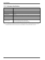
7.1.2
Performance Specifications..................................................................... 7-6
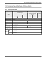
Common Specifications of Slave Units .................................................. 7-7
7.2.1
iv
Input Specifications ................................................................................. 7-7
Table of Contents
7.3
7.4
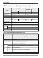
7.2.2
Output Specifications (Excluding the Relay Output Type) ...................... 7-8
7.2.3
Output Specifications (Relay Output Type)............................................. 7-8
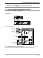
Internal Circuit Diagram, Terminal Layout .............................................. 7-9
7.3.1
Slave Unit, Standard Type (Item No. AFPRP1 Series) ........................... 7-9
7.3.2
Slave Unit, Compact Type (Connector Terminal Block)
(Item No. AFPRP2 Series) ........................................................................ 7-12
7.3.3
Slave Unit, Compact Type (Relay Output) (Item No. AFPRP2Y04R
Series) ................................................................................................... 7-15
7.3.4
Slave Unit, Compact Type (e-CON)
(Item No. AFPRP2X08D2E Series) ...................................................... 7-17
Dimension Diagram .............................................................................. 7-18
7.4.1
Slave Unit, Standard Type (Item No. AFPRP1 Series) ......................... 7-18
7.4.2
Slave Unit, Compact Type (Connector Terminal Block)
(Item No. AFPRP2 Series) ........................................................................ 7-20
7.4.3
Slave Unit, Compact Type (Relay Output) (Item No. AFPRP2Y04R
Series) ................................................................................................... 7-21
7.4.4
Slave Unit, Compact Type (e-CON)
(Item No. AFPRP2X08D2E Series) ...................................................... 7-22
v
Table of Contents
vi
1
System Configuration and
Restrictions on Combination
System Configuration and
Restrictions on Combination
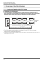
1.1 Overview of the PHLS System
1.1.1 Function and Operation of the PHLS System
Functions of the PHLS System
• The PHLS system is a high-speed remote I/O system that can be connected to the FP7
series. Input/output units connected to the network can be controlled by way of the shielded
twisted pair cable, thereby relieving work for input/output wiring and saving space.
31 or 32 units
Master unit
Slave unit
Slave unit
Slave unit
Slave unit
Port 1
Slave unit
Slave unit
Slave unit
Slave unit
Up to 63
units
Port 2
31 or 32 units
Max. transmission distance 100 m (with 12 Mbps) / 200 m (with 6 Mbps)
• The PHLS system can be handled as an ordinary I/O on the FP7 CPU unit, thereby
dispensing with complicated programming.
• A fixed-time communication method is used. This retains a constant scan time even when a
transmission error occurs.
1-2
1.1 Overview of the PHLS System
• Key specifications of PHLS
Items
Description
Transmission line
Shielded twisted pair cable
Baud rate
12 Mbps/ 6 Mbps ( Use the switch on the body )
Transmission scan time
0.03 ms/ 1 slave, 1.86 ms/ 63slave (with Baud rate 12 Mbps)
Max. transmission distance
100 m (with 12 Mbps) , 200 m (with 6 Mbps )
Controllable I/O points
Max. 1,008 points (per master unit)
Slave units
Max. 63 units (per master unit)
(Note 1) Configure all the wiring systems using the same type of cable. Do not mix different types of cables.
(Note 2) The figure above indicates performance using a recommended cable. The indicated performance may not be
available if a recommended cable is not used.
1-3
System Configuration and
Restrictions on Combination
1.2 List of System Component Devices
1.2.1 List of Units
Master unit
Used in combination with the FP7 CPU unit.
AFP7PHLSM
Slave unit terminal block type
• Both I/O and transmission line can be connected using MP3 screws.
AFPRP1X8D2
Input: 8 points
AFPRP1X16D2
Input: 16 points
AFPRP1Y16T
Output: 16 transistor points
AFPRP1XY16D2T
Input: 8 points, Output: 8 transistor points
Slave unit compact type
• Space-saving size of W59.5mm × H57.5mm × D40mm)
• An e-CON type input is also available. This saves work for wiring.
1-4
AFPRP2X16D2
Input: 16 points
AFPRP2Y16T
Output: 16 points
AFPRP2X08D2E
Input: 8 points
AFPRP2Y04R
Output: 4 relay points
AFPRP2XY16D2T
Input: 8 points,
Output: 8 transistor points
1.2 List of System Component Devices
1.2.2 List of Component Units
Master unit
Product name
Description
FP7 PHLS master unit
Interface unit to connect FP7 to the PHLS system.
Controllable I/O points per master unit: 1,008
Slave unit
Type
Terminal
Block Type
Connection
method
Screw terminal
block (M3)
e-CON connector
Compact type
Connector
terminal block
Relay output
No. of I/O points
Output type
Model no.
AFP7PHLSM
Model no.
Input: 8 points
−
AFPRP1X08D2
Input: 16 points
−
AFPRP1X16D2
Input: 8 points /
Output: 8points
Transistor (sink type)
AFPRP1XY16D2T
Output: 16 points
Transistor (sink type)
AFPRP1Y16T
Input: 8 points
−
AFPRP2X08D2E
Input: 16 points
−
AFPRP2X16D2
Input: 8 points /
Output: 8 points
Transistor (sink type)
AFPRP2XY16D2T
Output: 16 points
Transistor (sink type)
AFPRP2Y16T
Output: 4 points
Relay output
AFPRP2Y04R
1.2.3 Selection of Cables
Use the cable indicated below.
Recommended cables
Item
Specifications
Classification
Two-wire shielded twisted pair cable
Conductor size
AWG#22
Characteristic impedance
100 Ω
Insulator
Cross-linked formed polyethylene
(Note 1) Configure all the wiring systems using the same type of cable. Do not mix different types of cables.
(Note 2) The indicated performance (e.g. Max. transmission distance, Max. slave units) may not be available if a
recommended cable is not used.
Recommended cable
ZHY221PS manufactured by Shinko Seisen Industry Co., Ltd.
1-5
System Configuration and
Restrictions on Combination
1.3 Restrictions on Combination
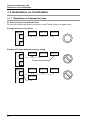
1.3.1 Restrictions on Transmission Lines
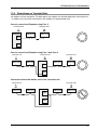
How to connect transmission lines
Connect the lines so that there is no branch. Avoid T-letter wiring or octopus wiring.
Example of correct connection
Master unit
Slave unit
Slave unit
Slave unit
Port 1
Port 2
Example of T-letter wiring and octopus wiring
Master unit
Slave unit
Slave unit
Slave unit
Slave unit
Slave unit
Slave unit
Port 1
Port 2
Master unit
Port 1
Slave unit
Port 2
1-6
1.3 Restrictions on Combination
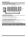
1.3.2 Restrictions on Terminal Units
• A master unit has two ports. For both ports, the master unit should always be a terminal unit.
A master unit cannot be connected in the middle of a transmission line.
Correct connection (Example using Port 1)
Terminal unit
Master unit
Terminal unit
Slave unit
Slave unit
Port 1
Port 2
Correct connection (Example using Port 1 and Port 2)
Terminal unit
Slave unit
Terminal unit
Slave unit
Master unit
Terminal unit
Slave unit
Slave unit
Port 1
Port 2
Connection where the master unit is not a terminal unit
Terminal unit
Slave unit
Terminal unit
Slave unit
Master unit
Slave unit
Slave unit
Port 1
Port 2
1-7
System Configuration and
Restrictions on Combination
1.3.3 Restrictions on Transmission Distance
"Transmission distance" refers to the length of a single transmission line.
31 or 32 units
Slave unit
Master unit
Slave unit
Slave unit
Slave unit
Port 1
Slave unit
Slave unit
Slave unit
Slave unit
Up to 63
units
Port 2
31 or 32 units
Max. transmission distance 100 m (with 12 Mbps) / 200 m (with 6 Mbps)
1.3.4 Restrictions on Slave Units
Max. number of connectable slave units
• Up to 63 slave units can be connected to one master unit.
• Up to 32 slave units can be connected to one transmission line.
1.3.5 Restrictions on Installation of Master Units
Max. number of installable master units
Up to 16 FP7 PHLS master units can be controlled by the FP7 CPU unit.
Restrictions based on current consumption
Internal current consumption by a unit is as indicated below. Make sure that the total
consumption including other units is within the power supply capacity to be used.
Name
FP7 PHLS master unit
1-8
Model no.
AFP7PHLSM
Current consumption
100 mA or less
2
Names and Functions of
Parts
Names and Functions of Parts
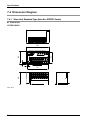
2.1 FP7 PHLS Master Unit
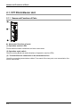
2.1.1 Names and Functions of Parts
Names and functions of parts
(1) Operation monitor LEDs
Shows communication conditions and error occurrence.
(2) Operation mode switch
Used for setting Baud rate and indications of operation monitor LEDs.
(3) Terminal block for connection to the transmission line
Used for connecting transmission cables. From each of the two ports, one transmission line
can be connected.
2-2
2.1 FP7 PHLS Master Unit
2.1.2 Operation Monitor LEDs
LED indications and their meanings
Signs and LED colors
Description
PWR
Blue
Turns on when the power is ON.
1 × n - 16 × n
Green
Indicates the setting status or the communication status of each slave unit.
Depending on settings of the operation mode switch, the slave number to be
monitored varies.
COMM.
Green
Turns on while communicating with the slave.
ERR
Red
Turns on when an error occurs in communication with the specified slave.
ALM
Red
Turns on when an error in communication with the specified slave does not recover
after retry.
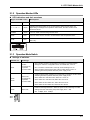
2.1.3 Operation Mode Switch
Settings of switches
Switch no.
Settings
SW1
Status
monitored by
operation
monitor LEDs
SW2
SW3
Slave unit
monitored by
operation
monitor LEDs
ON: The slave number, as specified in the "Select a connected slave"
dialog box under the configuration menu of FPWIN GR7, turns on.
OFF: The slave number that is currently communicating turns on.
Slave numbers larger than the Max. slave number does not turn on.
Switching becomes possible while the power supply is ON.
Used for setting slave numbers to be monitored by operation monitor LEDs.
Switching becomes possible while the power supply is ON.
When SW2: OFF and SW3: OFF, Slave No.1 to No.15
When SW2: OFF and SW3: ON, Slave No.16 to No.31
When SW2: ON and SW3: OFF, Slave No.32 to No.47
When SW2: ON and SW3: ON, Slave No.48 to No.63
SW4
Baud rate
Used for switching Baud rate. While the power is ON, switching is invalid.
Settings become valid during the power supply OFF → ON.
ON: 12 Mbps, OFF: 6 Mbps
2-3
Names and Functions of Parts
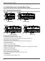
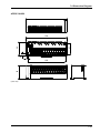
2.2 PHLS Slave Unit, Terminal Block Type
2.2.1 Names and Functions of Parts
OFF
TERM
ON
H 12
ON
C 6
O FF
COM.
POWER
OFF
ON
C 6
O FF
AFPRP1X08D2
No.
TERM
ON
H 12
COM.
TERM
ON
H 12
ON
C 6
O FF
COM.
AFPRP1X16D2
No.
AFPRP1X08D2
OFF
POWER
AFPRP1X16D2
POWER
OFF
AFPRP1XY16D2T
No.
TERM
ON
H 12
ON
C 6
O FF
COM.
POWER
AFPRP1Y16T
No.
AFPRP1XY16D2T
AFPRP1Y16T
Names and functions of parts
(1) Termination resistance selector switch
Set to ON when the slave becomes a terminal unit of the transmission line.
(2) Operation mode setting switches
Used for setting slave numbers, Baud rate and output status during error.
(3) Unit mounting hole
Used for mounting with screws.
(4) Power supply and I/O terminal block
Used for connecting transmission cables, power supply for unit driving, and I/O devices.
(5) DIN rail attachment hook
Used for attachment to the DIN rail.
(6) I/O circuit operation monitor LEDs
Shows ON/OFF status of the input circuit or the output circuit.
(7) POWER LED
Turns on when the slave unit power is ON.
2-4
2.2 PHLS Slave Unit, Terminal Block Type
(8) Communication status LED
Shows the status of communication with the master unit.
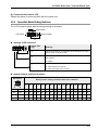
2.2.2 Operation Mode Setting Switches
Turn off the power supply before making settings or changes.
Slide switch
DIP switch
Rotary switch
Settings of DIP switches
Switch part
sign
Settings
No.
Set slave numbers by a combination of the settings of the rotary
switch. Refer to the table below.
Set Baud rate.
12
12: 12 Mbps
6
6: 6 Mbps
Set the output status when a transmission error occurs.
H
H: Hold: Outputs are retained.
C
C: Clear: All outputs are turned off.
Switch settings and slave numbers
DIP switch
Rotary switch settings and allocated slave numbers
0
1
2
3
4
5
6
7
8
9
A
B
C
D
E
F
ON
ON
-
1
2
3
4
5
6
7
8
9
10
11
12
13
14
15
ON
OFF
16
17
18
19
20
21
22
23
24
25
26
27
28
29
30
31
OFF
ON
32
33
34
35
36
37
38
39
40
41
42
43
44
45
46
47
OFF
OFF
48
49
50
51
52
53
54
55
56
57
58
59
60
61
62
63
(Note) Slave No.0 cannot be used.
2-5
Names and Functions of Parts
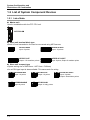
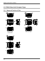
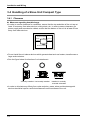
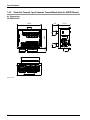
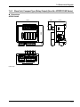
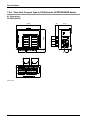
2.3 PHLS Slave Unit Compact Type
2.3.1 Names and Functions of Parts
⑩
⑪
⑪
e-CON type
2-6
⑪
Relay Output type
Connector-Type
Terminal Block
⑩
⑩
2.3 PHLS Slave Unit Compact Type
Names and functions of parts
(1) POWER LED
Turns on when the slave unit power is ON.
(2) Communication status LED
Shows the status of communication with the master unit.
(3) Mode selector switches
Used for setting slave numbers, Baud rate and output status during error.
(4) I/O circuit operation monitor LEDs
Shows ON/OFF status of the input circuit or the output circuit.
(5) DIN rail attachment hook
Used for attachment to the DIN rail.
(6) Terminal block for connection of the I/O circuit (CN1: 10P, CN2: 11P)
Used for connecting I/O devices.
(7) Terminal block for connection of the relay output circuit (7P)
Used for connecting output devices.
(8) e-CON socket for connection of the input circuit (4P×8)
Used for connecting input devices. e-CON should be used for connection.
(9) Termination resistance selector switch
Set to ON when the slave becomes a terminal unit of the transmission line.
(10) Terminal block for power supply
Used for connecting a unit driving power supply 24 V.
(11) Terminal block for connection to the transmission line
Used for connecting transmission cables. The two TR+ terminals, TR- terminals, and earth
terminals are respectively connected inside.
2-7
Names and Functions of Parts
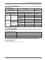
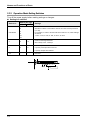
2.3.2 Operation Mode Setting Switches
Turn off the power supply before making settings or changes.
Settings of switches
Switch no.
Switch part sign
(ON)
(OFF)
1
Set slave numbers in accordance with the sum of the five dip switches
(1 to 63).
2
5/6/7/8/9/10
4
For example, in order to set the total slave number to 10, make settings
as follows.
8
16
1: OFF, 2: ON, 4: OFF, 8: ON, 16: OFF, 32: OFF
32
4
6
Settings
12
Used for switching Baud rate.
ON: 6 M bps, OFF: 12 M bps
Set the output status when a transmission error occurs.
3
C
H
C (Clear): All outputs are turned off.
H (Hold): Outputs are retained.
1/2
2-8
−
−
Not used
3
Installation and Wiring
Installation and Wiring
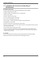
3.1 Installation Environment and Handling of
Environment
Ambient environment
Use the unit within the range of the general specifications when installing
• Ambient temperatures: 0 to +55°C
• Ambient humidity: 10 to 95%RH (at 25°C, no-condensing)
• Altitude: up to 2,000 m
• Location: Inside the control board
• For use in pollution degree 2 environment.
Do not use it in the following environments.
• Direct sunlight — Sudden temperature changes causing condensation.
• Inflammable or corrosive gas.
• Excessive airborne dust, metal particles or saline matter.
• Benzine, paint thinner, alcohol or other organic solvents or strong alkaline solutions such as
ammonia or caustic soda.
• Direct vibration, shock or direct drop of water.
• Influence from power transmission lines, high voltage equipment, power cables, power
equipment, radio transmitters, or any other equipment that would generate high switching
surges. (100 mm or more)
Handling
Do not touch connector pins directly to prevent static electricity from causing damage.
Always rid yourself of any static electricity before handling this product.
3-2
3.2 Installation and Wiring of the Master Unit
3.2 Installation and Wiring of the Master Unit
3.2.1 Installation
For installation of the master unit, please see the FP7 CPU Unit Users Manual (Hardware).
3.2.2 Wiring
Respectively connect TR+ and TR- of the PHLS master unit with TR+ and TR- of the PHLS
slave unit.
Connect the shielded wire of the transmission cable to the functional earth terminal of the
slave unit.
PHLS master unit
PHLS slave unit
TR+
TR+ TR-
TR-
3.2.3 Hard Wiring
Suitable transmission cable (Recommended product)
Shinko Seisen Industry Co., Ltd.: ZHY221PS
Suitable solderless terminal
M3 terminal screws are used for the solderless terminal. Use the solderless terminal specified
below.
Fork type terminal
6 mm or less
6 mm or less
3.2 mm or more
Manufacturer
J.S.T. Mfg Co.,Ltd
Round type terminal
Shape
3.2 mm or more
Part no.
Fork type
1.25-B3A
Round type
1.25-MS3
Suitable wires
0.25 to 1.65 mm
2
Screwing torque for the terminal block
0.5 to 0.6 N∙m
3-3
Installation and Wiring
3.3 Handling of a Slave Unit, Standard Type
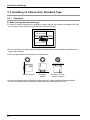
3.3.1 Clearance
Measures regarding heat discharge
• In order to secure clearance for ventilation, ensure that the top, bottom and sides of the unit
are at least 10 mm away from other devices, wiring ducts, etc.
10 mm or more
10 mm
or more
10 mm
or more
10 mm or more
• Do not install the unit above devices which generate heat such as heaters, transformers or
large scale resistors.
• See the figure below for direction of unit attachment.
Vertically installed
Horizontally
installed
Installed in vertically
reversed orientation
• In order to eliminate any effects from noise emission, power wires and electromagnetic
devices should be kept at a sufficient distance from the surfaces of the unit.
3-4
3.3 Handling of a Slave Unit, Standard Type
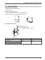
3.3.2 Attachment Methods
Attachment to the DIN rail
1. Hang the slave unit over the DIN rail.
2. Press in the unit.
Removal from the DIN rail
1. Pull out the attachment lever using a flathead screwdriver.
2. While pulling up the unit, remove it from the DIN rail.
1
2
2
1
Installation with screws
M4 washer built-in screw
(Washer size: ø9mm or less)
• Tightening torque: 0.6 to 1.08N•m
B
6 mm
A
M4 tap
Model no.
AFPRP1X08D2
A (mm)
B (mm)
75 ± 0.4
41 ± 0.4
128 ± 0.4
41 ± 0.4
AFPRP1X16D2
AFPRP1Y16T
AFPRP1XY16D2T
3-5
Installation and Wiring
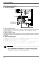
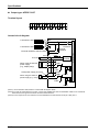
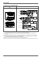
3.3.3 Precautions on Wiring
Internal circuit diagram
TR+
Transmission cable
TR-
Pulse
Transformer
Transmission cable
Terminal resistance selector switch
24 V+
24 V DC
24 V+
Contact switch
-
Xn
+
When using the
internal power supply
(e.g., display lamp)
Fuse:
2.5 A
Yn
DC /DC
converter
COM+
COM+
COMApprox. 7.5 kW
Internal circuit
Terminal
resistance
COM+
COM-
COMCOM+
Wiring the power supply
For the purpose of internal circuit driving, supply 24 V DC from outside to the 24 V+ and 24 Vterminals. These are connected to the + terminals and - terminals inside, and power is
supplied to I/O devices.
Wiring of the input circuit
In the case of contact input or no-voltage input, connect to the respective input terminals and terminals. In the case of an input device that requires power supply (e.g. sensor), + terminals
can be used.
Wiring of the output circuit
In the case of rated 24 V DC load, connect to the respective output terminals and + terminals.
As a DC type inductive load, attach a counter EMF absorption diode.
Wiring of transmission Lines
Terminals for connection to the transmission line (TR+, TR- and earth terminals) should be
connected in a daisy chain wiring. Avoid T-letter wiring or octopus wiring. In order to avoid
influence of noise, connect the shielded wire of the transmission cable on one side to the
functional earth terminal, and make sure to ground the functional earth terminal.
KEY POINTS
3-6
•
Do not supply power from outside to the + terminals and the - terminals.
•
In the input circuit or the output circuit, the maximum current that can be
withdrawn from the internal circuit (24 V DC) is 2 A.
3.3 Handling of a Slave Unit, Standard Type
REFERENCE
In the internal circuit diagram on the previous page, a typical example of the mixed
input/output unit AFPRP1XY16D2T is indicated. For specifications of individual slave
unit, please see 7.3 Internal Circuit Diagram, Terminal Layout .
3.3.4 Hard Wiring
Suitable wire (Transmission cable)
Item
Specifications
Classification
Two-wire shielded twisted pair cable
Conductor size
AWG#22
Characteristic impedance
100 Ω
Insulator
Cross-linked formed polyethylene
(Note 1) Configure all the wiring systems using the same type of cable. Do not mix different types of cables.
The indicated performance (e.g. Max. transmission distance, Max. slave units) may not be available if a
recommended cable is not used.
Recommended cable (transmission cable)
ZHY221PS manufactured by Shinko Seisen Industry Co., Ltd.
Suitable wire (Power supply and I/O)
Item
Specifications
Conductor size
AWG22 to 14
Rated temperature
60 to 75 °C
Suitable solderless terminal
M3 terminal screws are used for the terminal. The following suitable solderless terminals are
recommended for wiring to the terminals.
Manufacturer
J.S.T. Mfg Co.,Ltd
Shape
Part no.
Round type
1.25-MS3
Fork type
1.25-B3A
Round type
2-MS3
Fork type
2-N3A
Suitable wires
0.25 to 1.65 mm
2
1.04 to 2.63 mm
2
Screwing torque for the terminal block
0.6 to 0.8N∙m
3-7
Installation and Wiring
3.4 Handling of a Slave Unit Compact Type
3.4.1 Clearance
Measures regarding heat discharge
• In order to secure clearance for ventilation, ensure that the top and sides of the unit are at
least 10 mm away from other devices, wiring ducts, etc. In order to secure clearance for
power supply and transmission cables, ensure that the bottom of the unit is at least 50 mm
away from other devices.
10 mm or more
10 mm
or more
10 mm
or more
50 mm or more
• Do not install the unit above devices which generate heat such as heaters, transformers or
large scale resistors.
• See the figure below for direction of unit attachment.
Vertically installed Horizontally installed
Installed in vertically
reversed orientation
• In order to eliminate any effects from noise emission, power wires and electromagnetic
devices should be kept at a sufficient distance from the surfaces of the unit.
3-8
3.4 Handling of a Slave Unit Compact Type
3.4.2 Attachment Methods
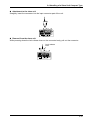
Attachment to the DIN rail
1. Hang the slave unit over the DIN rail.
2. Press in the unit.
2
1
Removal from the DIN rail
1. Pull out the attachment lever using a flathead screwdriver. Alternatively, press the lever
from the opposite side.
2. While pulling up the unit, remove it from the DIN rail.
1
2
2
1
Push
3-9
Installation and Wiring
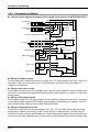
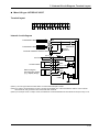
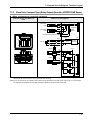
3.4.3 Precautions for Wiring
Transmission
cable
Transmission
cable
TR+
TR-
Pulse
Transformer
TR+
TR-
Terminal
resistance
Internal circuit
Internal circuit diagram (Examples of the mixed input/output unit AFPRP2XY16D2T )
Terminal resistance selector switch
Contact switch
+24 V
Fuse
2.5 A
+24 V
Relay, valve
DC /DC
converter
+24 V
Approx. 5.6 kW
+24 V
Approx.
5.6 kW
NPN output 3-wire
sensor
NC
+
Yn
Yn
VSP
+24 V
Internal circuit
24 V DC
24 V+
24 V+
24 V24 V+
Xn
Xn
Display lamp
Wiring the power supply
For the purpose of internal circuit driving, supply 24 V DC from outside to the 24 V+ and 24 Vterminals. These are connected to the + terminals and - terminals inside, and power is
supplied to I/O devices.
Wiring of the input circuit
In the case of contact input or no-voltage input, connect to the respective input terminals and terminals. In the case of an input device that requires power supply (e.g. sensor), + terminals
can be used.
Wiring of the output circuit
In the case of rated 24 V DC load, connect to the respective output terminals and + terminals.
In the case of relay output AFPRP2Y04R, power supply for load driving is required. As a DC
type inductive load, attach a counter EMF absorption diode.
Wiring of transmission Lines
Terminals for connection to the transmission line (TR+, TR- and earth terminals) should be
connected in a daisy chain wiring. Avoid T-letter wiring or octopus wiring. In order to avoid
influence of noise, connect the shielded wire of the transmission cable to the functional earth
terminal on one side, and make sure to ground the functional earth terminal on the other side.
3-10
3.4 Handling of a Slave Unit Compact Type
KEY POINTS
•
Do not supply power from outside to the + terminals and the - terminals.
•
In the input circuit or the output circuit, the maximum current that can be
withdrawn from the internal circuit (24 V DC) is 2 A.
REFERENCE
In the internal circuit diagram on the previous page, a typical example of the mixed
input/output unit AFPRP2XY16D2T is indicated. For specifications of individual slave
unit, please see 7.3 Internal Circuit Diagram, Terminal Layout .
3-11
Installation and Wiring
3.4.4 Hard Wiring for Connector Terminal Blocks
Suitable wire (Transmission cable)
Item
Specifications
Classification
Two-wire shielded twisted pair cable
Conductor size
AWG#22
Characteristic impedance
100 Ω
Insulator
Cross-linked formed polyethylene
Recommended Cable
ZHY221PS manufactured by Shinko Seisen Industry Co., Ltd.
(Note 1) Configure all the wiring systems using the same type of cable. Do not mix different types of cables.
The indicated performance (e.g. Max. transmission distance, Max. slave units) may not be available if a
recommended cable is not used.
Recommended cable (transmission cable)
ZHY221PS manufactured by Shinko Seisen Industry Co., Ltd.
Suitable wire (Power supply and I/O)
Name
Connector terminal block type
Power supply cable
Input cable
AWG24 to 16 (Copper strand wire)
Rated temperature: 60 to 75 °C
Output cable
Relay output type
AWG24 to 16 (Copper strand wire)
Rated temperature: 60 to 75 °C
AWG22 to 14 (Copper strand wire)
Rated temperature: 60 to 75 °C
Tightening torque
Name
Power supply terminal block,
Communication terminal block
Input terminal block
Output terminal block
3-12
Connector terminal block type
Relay output type
0.22 to 0.25 N·m
0.22 to 0.25 N·m
0.5 to 0.6 N·m
3.4 Handling of a Slave Unit Compact Type
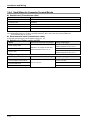
3.4.5 Wiring of Connector Terminal Block
1. Remove a potion of the wire’s insulation.
7 mm
2. Insert wire into terminal hole until it stops. Tighten screw clockwise to fix wire in place.
Precautions on wiring
The following precautions should be observed, to avoid broken or disconnected wires.
• When removing the wire’s insulation, be careful not to scratch the core wire.
• Do not twist the wires to connect them.
• Do not solder the wires to connect them. The solder may break due to vibration.
• After wiring, make sure stress is not applied to the wire.
• In the terminal block socket construction, if the wire is fastened upon counter-clockwise
rotation of the screw, the connection is faulty. Disconnect the wire, check the terminal hole,
and then re-connect the wire.
Clockwise
Counter clockwise
3-13
Installation and Wiring
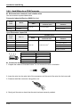
3.4.6 Hard Wiring for e-CON Connector
Recommended connector and suitable wires
Use a connector as prescribed below.
Panasonic Industrial Devices SUNX Co. Ltd.
Cover
color
Suitable wires
Model
Yellow
CN-EP2
Orange
CN-EP3
Nominal crosssectional area
AWG
27 to 20
0.1 to 0.5 mm
2
Finished outside
diameter
φ1.0 to φ1.15 mm
φ0.6 to φ0.9 mm
Tyco Electronics Japan G.K.
Cover
color
Suitable wires
Part no.
Nominal crosssectional area
AWG
Finished outside
diameter
Green
4-1473562-4
Blue
2-1473562-4
Yellow
1473562-4
Red
1-1473562-4
φ0.9 to φ1.0 mm
Orange
3-1473562-4
φ0.6 to φ0.9 mm
φ1.35 to φ1.6 mm
φ1.15 to φ1.35 mm
28 to 20
0.08 to 0.6 mm
2
φ1.0 to φ1.15 mm
Terminal layout for the connector part
4 3 2 1
Terminal no.
Terminal name
1
+
2
NC
3
-
4
Input
Connection method
1. Prepare the cable as illustrated below. Do not remove the wire’s insulation.
2. Insert the wire into the wire inlet of the connector until the end of the wire hits the inner wall.
3. Pressure-weld the connector using pliers, etc.
4. Gently pull the wire to check that the wire has been securely welded.
3-14
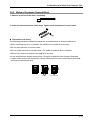
3.4 Handling of a Slave Unit Compact Type
Attachment to the slave unit
Straightly insert the connector into the input connector part of the unit.
Removal from the slave unit
While pressing down the lock release lever on the connector body, pull out the connector.
Lock release
lever
3-15
4
Unit Settings and
Configuration
Unit Settings and Configuration
4.1 Switch Settings for Slave Units
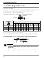
4.1.1 Slave No. Settings
Slave numbers are used by the master unit to identify slave units. For each of the slave units
connected to the same master unit, specify a unique number between 1 and 63.
How to set slave numbers for a standard type
Specify slave numbers using a combination of DIP switch and rotary switch.
Slide switch
DIP switch
DIP switch
Rotary switch
Rotary switch settings and allocated slave numbers
0
1
2
3
4
5
6
7
8
9
A
B
C
D
E
F
ON
ON
−
1
2
3
4
5
6
7
8
9
10
11
12
13
14
15
ON
OFF
16
17
18
19
20
21
22
23
24
25
26
27
28
29
30
31
OFF
ON
32
33
34
35
36
37
38
39
40
41
42
43
44
45
46
47
OFF
OFF
48
49
50
51
52
53
54
55
56
57
58
59
60
61
62
63
(Note) Slave No.0 cannot be used.
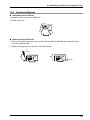
How to set slave numbers for a compact type
To each slave number to be allocated, an address is provided by adding corresponding bit
figures from 1, 2, 4, 8, 16, and 32. Switches for the relevant figures are turned on the slave
unit.
E.g. When a slave number is set to "5", 1 and 2 are turned on, and the other figures are turned off.
KEY POINTS
4-2
•
It is recommended to allocate slave numbers using consecutive numbers
starting with 1.
•
Because the PHLS master unit does not communicate with slaves that have
numbers larger than the Max. slave number, it is recommended to set the
Max. slave number as small as possible to enable speedy scanning.
4.1 Switch Settings for Slave Units
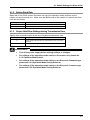
4.1.2 Setting Baud Rate
Baud rate of the PHLS system should be set using the operation mode switches on the
master unit and the slave unit. Make sure that Baud rates of the master unit and all the slave
units are consistent.
Switch position
Baud rate
12
12 Mbps
6
6 Mbps
4.1.3 Output Hold/Clear Settings during Transmission Error
Specify how to handle output at the time of system transmission error.
Switch position
Output operation at the time of transmission error
H
Hold: Output status before the transmission error occurred is
retained.
C
Clear: The OFF signal is output.
REFERENCE
•
Turn off the power supply before making settings or changes.
•
For settings of the operation mode switch on the master unit, please see
2.1.3 Operation Mode Switch.
•
For settings of the operation mode switch on the Slave unit, Standard type,
please see 2.2.2 Operation Mode Setting Switches.
•
For settings of the operation mode switch on the Slave unit, Compact type,
please see 2.3.2 Operation Mode Setting Switches.
4-3
Unit Settings and Configuration
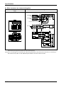
4.2 I/O No. Allocation
4.2.1 Allocation of the Master Unit in the I/O Map
The PHLS master unit should be allocated in the I/O map using the tool software FPWIN GR7.
How to allocate the master unit
PROCEDURE
1. From the menu bar, select "Option" → "FP7 Configuration".
2. In the left pane, select "I/O Map".
3. Double click a slot to which the PHLS master unit is to be installed.
The “Unit selection” dialog box is displayed.
4. In the field for selection of units to be used, select "Communications" and
"PHLS master unit".
5. For input words and output words, enter the same value as "End slave no.".
6. Press [OK] button.
KEY POINTS
•
4-4
In the PHLS system, each slave occupies I/O numbers for 16 points.
4.2 I/O No. Allocation
4.2.2 I/O Number Allocated to Slaves
I/O numbers allocated to slaves of the PHLS system are determined based on the initial word
number of the connected master unit and the slave number.
Slave types and allocated I/O numbers
I/O numbers listed below indicate cases where the initial word number is "10" and the slave
number is "1".
Item number for
the standard type
Item number for the
compact type
I/O No.
No. of I/O
points
Input
Output
AFPRP1X08D2
AFPRP2X08D2E (e-CON)
Input: 8 points
X100 to X107
−
AFPRP1X16D2
AFPRP2X16D2
Input: 16 points
X100 to X10F
−
AFPRP1XY16D2T
AFPRP2XY16D2T
Input: 8 points /
Output: 8 points
X100 to X107
Y108 to Y10F
AFPRP1Y16T
AFPRP2Y16T
Output: 16 points
−
Y100 to Y10F
−
AFPRP2Y04R (Relay)
Output: 4 points
Y100 to Y103
−
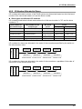
Order of allocated I/O numbers
I/O numbers for slaves are allocated in the order of slave numbers specified by the switch on
the relevant slave units.
Master unit
Power
C
P
U
Input:
16 points
Output:
16 points
Input:
16 points
Output:
16 points
Slave No.1
Slave No.2
Slave No.3
Slave No.4
X100 to X10F Y110 to Y11F
X120 to X12F Y130 to Y13F
I/O numbers for slaves are allocated in the order of slave numbers, regardless of the order of
connection of the relevant slave units.
Master unit
Power
C
P
U
Input:
16 points
Output:
16 points
Input:
16 points
Output:
16 points
Slave No.1
Slave No.3
Slave No.2
Slave No.4
X100 to X10F Y120 to Y12F
X110 to X11F Y130 to Y13F
4-5
Unit Settings and Configuration
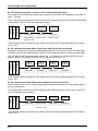
I/O numbers allocated to slaves of the mixed input/output type
In the case of the mixed input/output type, consecutive numbers are allocated in the order of
Input → Output.
E.g. In the case of a slave with 8 input points and 8 output points, X100 to X107 are allocated
to Input, and Y108 to Y10F are allocated to Output.
Master unit
Power
C
P
U
Input: 8 points /
Output: 8points
Input:
16 points
Output:
16 points
Slave No.1
Slave No.2
Slave No.3
X100 to X107 X110 to Y11F
Y108 to Y10F
Y120 to Y12F
(The example above indicates a case where the initial word number allocated to the master
unit is "10". )
I/O numbers allocated when 4-point type and 8-point type are mixed
Because numbers for 16 points are allocated whether the unit is 4-point type or 8-point type,
numbers from the final allocated I/O number to the subsequent slave number become dead.
E.g. If X100 to X107 are allocated to a slave No. 1 of 8-point type, X108 to X10F become
dead numbers. I/O numbers for Slave No. 2 start with X110 or Y110.
Master unit
Power
C
P
U
Input:
8 points
Input:
16 points
Slave No.1
Slave No.2
X100 to X107 X110 to X11F
Output:
4 points
Output:
16 points
Slave No.3
Slave No.4
Y120 to Y123 Y130 to Y13F
(The example above indicates a case where the initial word number allocated to the master
unit is "10".)
I/O numbers allocated when slave numbers are not consecutive
Dead numbers also occur in cases where slave numbers allocated to the connected slaves
are not consecutive.
E.g. If Slaves No.1 and No.3 are allocated and No.2 does not exist, X110 to X11F and Y110
to Y11F become dead numbers.
Master unit
Power
C
P
U
Input:
16 points
Slave No.1
(Dead numbers)
X100 to X10F X110 to X11F
Y110 to Y11F
Input:
16 points
Output:
16 points
Slave No.3
Slave No.4
X120 to X12F Y130 to Y13F
(The example above indicates a case where the initial word number allocated to the master
unit is "10".)
4-6
4.2 I/O No. Allocation
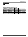
KEY POINTS
•
The initial word number of a slave unit should be calculated as follows.
•
[Initial word No.] + [Slave No.] - 1 = Slave word No.
E.g. If the initial word number allocated to the master unit is "10", and the slave number is "5",
the I/O word number allocated to the relevant slave is "14".
Item number for
the standard type
I/O No.
Item number for the
compact type
No. of I/O
points
AFPRP1X08D2
AFPRP2X08D2E (e-CON)
Input: 8 points
X140 to X147
−
AFPRP1X16D2
AFPRP2X16D2
Input: 16 points
X140 to X14F
−
AFPRP1XY16D2T
AFPRP2XY16D2T
Input: 8 points /
Output: 8 points
X140 to X147
Y148 to Y14F
AFPRP1Y16T
AFPRP2Y16T
Output: 16 points
−
Y140 to Y14F
−
AFPRP2Y04R (Relay)
Output: 4 points
Y140 to Y143
−
Input
Output
4-7
Unit Settings and Configuration
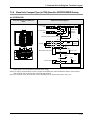
4.3 Configuration Concerning PHLS
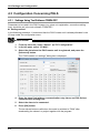
4.3.1 Settings Using Tool Software FPWIN GR7
Parameters to be used in the PHLS system (e.g. slave unit registration, connection waiting
time) should be set in the tool software FPWIN GR7.
Setting method
In the following procedure, it is assumed that the PHLS master unit is already allocated in the
I/O map under the configuration menu.
PROCEDURE
1. From the menu bar, select "Option" → "FP7 Configuration".
2. In the left pane, select "I/O Map".
3. Select the slot where the PHLS master unit is registered, and press the
[Advanced] button.
The “PHLS master unit settings” dialog box is displayed.
4. Enter the slave final address, communication retry times, and PHLS slave
communication waiting time.
5. Select the slave to be connected.
6. Press [OK] button.
The set values become valid when the mode is switched to "RUN" after
downloading the values in a project together with the program.
4-8
4.3 Configuration Concerning PHLS
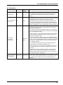
Setting item
Items
End slave No.
Communications
retry count
Default
63
3
Setting
range
1 to 63
3 to 7
Settings
Among the slave units to be connected, specify the slave
number that has the largest value. The master unit does not
communicate with slaves that have larger values than the
above.
Specify retry times in the case where communication cannot be
established between the master unit and the slave unit. An error
is detected if communication with the slave cannot be
established after retry has been made for the specified times.
Even if a communication error is recorded, communication is
automatically restarted once the cause of the error is removed.
When this happens, the Error LED remains in the same status.
Specify waiting time before communication is established with
the slave unit selected in the "Select slaves to be connected"
field, following power-up.
The above is valid not only following power-up, but also when
the mode is switched from PROG to RUN after downloading the
FP7 configuration or project.
While waiting for communication with the slave unit, the PROG
LED on the CPU unit flashes. While this LED is flashing, the
RUN mode cannot be used.
PHLS slave
connection
waiting time
0
0 to 300
(sec)
Once communication with the slave unit is established within
this time, the CPU unit becomes ready for transition to the RUN
mode. (The unit automatically transits to the RUN mode if power
is turned on in the RUN mode, or when the mode is switched
from PROG to RUN.)
If communication with the slave unit cannot be established
within this time, the master unit reports an error.
If the time is set to "0", the master unit continues waiting until
communication with the slave unit is established. (No error is
reported.)
Whether the master unit allows transition to the RUN mode,
while an error is being reported, depends on settings under
"Select operation when a self-test error occurs → A unit error
occurred" in the CPU configuration.
Turn on the check box for the number of slave to be connected.
Select slaves to
be connected
No check
01 to 63
If the slave of the specified number is not connected, an error
is reported after "PHLS slave connection waiting time" has
passed.
4-9
Unit Settings and Configuration
4.3.2 Final Slave No. and Settings and Operations Concerning "Select Slaves
to be Connected"
• The master unit does not communicate with slave units that have slave numbers larger than
the specified final slave number. Among the slave units to be connected, specify the slave
number that has the largest value for the final slave number.
• The master unit also communicates with units whose check boxes in "Select slaves to be
connected" are not turned on, as long as their slave numbers are smaller than the specified
final slave number. No connection waiting check is conducted for such commutation. No
error is reported, either, even if the relevant units are not connected.
KEY POINTS
4-10
•
Among the slave units to be connected, specify the slave number that has
the largest value for the final slave number. If this value is excessively large,
the transmission time will be longer.
•
Please note that slave units are activated even if their check boxes in
"Select slaves to be connected" are not turned on, as long as their slave
numbers are smaller than the final slave number. Operation is continued
without detecting an error, even if such slave units are turned on or off
during the RUN mode.
4.3 Configuration Concerning PHLS
4.3.3 Settings and Operations of PHLS Slave Connection Waiting Time
Depending on settings of PHLS slave connection waiting time, operations following power-up,
or when the mode is switched from PROG to RUN after downloading the FP7 configuration or
project, as follows.
Operation when the connection waiting time is set to "0"
• The master unit continues waiting until the slave unit selected in "Select slaves to be
connected" is started up. While waiting, the PROG. LED on the CPU unit flashes. During
this time, the RUN mode cannot be used.
• The mode is set to RUN when the slave is started up, following power-up in the RUN mode,
or when the mode is switched from PROG to RUN.
Operation when the connection waiting time is set to "1 to 300 seconds"
• The master unit continues waiting within the specified range of waiting time, until the slave
unit selected in "Select slaves to be connected" is started up. During this time, the PROG.
LED on the CPU unit flashes. During this time, the RUN mode cannot be used.
• The mode is set to RUN when the registered slave is started up within the specified waiting
time. (The mode can be switched to RUN.) The mode is automatically set to RUN, following
power-up in the RUN mode, or when the mode is switched from PROG to RUN.
• An error is reported if the time before the slave unit selected in "Select slaves to be
connected" is started up exceeds the specified connection waiting time. In this case, the
ERROR LED on the PHLS master unit turns on.
• The operation mode of the CPU unit at the time of error varies depending on settings of CPU
configuration ("Select operation when a self-test error occurs → A unit error occurred").
Select operation when a self-test
error occurs → A unit error
occurred
Operation when the time before the slave unit selected in "Select slaves to
be connected" is started up exceeds the specified connection waiting time
Stop operation
A unit error is reported. The CPU unit remains in the PROG. mode.
Continue operation
A unit error is reported. The CPU unit is switched to the RUN mode.
CPU configuration menu
4-11
Unit Settings and Configuration
4-12
5
Startup and Operation of the
PHLS System
Startup and Operation of the PHLS System
5.1 Startup of the PHLS System
5.1.1 Check Before Turning On the Power
In order to prevent malfunctions and accidents, check the following items before starting up
the system.
Items to be checked
1. Check to make sure the various devices have been connected as indicated by the design.
2. Make sure settings have been entered so that power supplies will be turned on according
to the procedure outlined in section “Procedure for Turning On the Power”.
3. Ensure that the CPU unit is started up in the PROG. mode by default.
5.1.2 Procedure for Turning On/Off the Power
In order to prevent malfunctions at the time of system startup or stop, observe the following
procedure to start up the PHLS system.
Procedure for turning on the power
1. Power on I/O devices connected to the PHLS slave unit.
2. Power on the PLHS slave unit.
3. Power on FP7 where the PHLS master unit is installed.
Procedure for turning off the power
1. Power off FP7 where the PHLS master unit is installed.
2. Power off the PLHS slave unit.
3. Power off I/O devices connected to the PHLS slave unit.
5-2
5.2 Pre-Operation Checks (Before Switching to the RUN Mode)
5.2 Pre-Operation Checks (Before Switching to the RUN Mode)
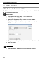
5.2.1 Check of Communication Status
• While the slave unit and the master unit are communicating normally, the COMM. LED
flashes. The numbers of the connected slaves can be confirmed by checking the operation
monitor LEDs of the master unit.
• Check that the COMM. LEDs on the master unit and all the slave units are turned on.
Subsequently, check that the numbers of the connected slaves are correct, by checking the
operation monitor LEDs of the master unit.
REFERENCE
•
For the operation monitor LEDs of the master unit, please see 6.2 What to
Do If an Error Occurs.
•
If there is abnormality (e.g. ERR. LED or ALARM LED is turned on), please
see 6.2 What to Do If an Error Occurs.
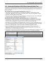
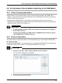
5.2.2 Check of Output Status
The output status of the PHLS system can be checked using the tool software FPWIN GR7.
Setting method
In the following procedure, it is assumed that the tool software FPWIN GR7 has already been
started up, and the PHLS master unit is already allocated in the I/O map.
PROCEDURE
1. From the menu bar, select "Debug" → "Force I/O functions".
The "Force I/O" dialog box is displayed.
2. Press the [Input device] button.
5-3
Startup and Operation of the PHLS System
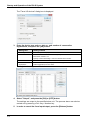
The "Force I/O devices" dialog box is displayed.
3. Enter the device type and no., slot no., and number of consecutive
registrations, and press the [OK] button.
Setting item
Setting method
Device type
Select "OT (direct output)".
No.
In accordance with the I/O allocation, specify the numbers. Note that the
initial word number is "0".
Specify a value subtracting 1 from the relevant slave number.
Slot No.
Enter the slot number where the master unit is installed.
No. of continuous
registrations
Enter the number of input/output points to be registered. Enter "16" to
enable registrations for one slave.
The registered settings are indicated.
4. Select "Output", and press the [ON] or [OFF] button.
The settings are output to the specified slave unit. The process above can also be
carried out by pressing <Ctrl> key + Number key.
5. In order to cancel the force input/output, press the [Release] button.
5-4
5.3 Response Times in the PHLS System
5.3 Response Times in the PHLS System
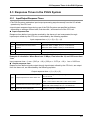
5.3.1 Input/Output Response Times
• The PHLS system undertakes input/output processing asynchronously from the I/O refresh
operation by the CPU unit.
• Input/output response times during use of the PHLS system are specified as follows,
depending on settings of Baud rate, final slave No., and scan time of the CPU unit.
Input response time
Response time before input signals received by the slave unit are incorporated, through
input/output refresh by the CPU unit, is calculated by the following equation.
Input response time = (1) + (2) + (3) + (4)
(1)
Input response time of the slave unit
1 ms or less
(2)
Transmission time of the PHLS
system
Baud rate: When 6 Mbps + 59.0 µs × Final slave No.
(3)
Scan time of the master unit
220 µs + 13.75 µs × Final slave No.
(4)
Scan time of the CPU unit
Varies by the program, settings and time.
Baud rate: When 12 Mbps, 29.5 µs × Final slave No.
Example of calculation: When Baud rate 12 Mbps, Final slave No.10, and CPU scan time
1 ms
Input response time = 1 ms + (29.5 µs × 10) + (220 µs + 13.75 µs × 10) + 1 ms = 2.653 ms.
Output response time
Response time before signals output through input/output refresh by the CPU unit, are output
from the slave unit, are calculated by the following equation.
Output response time = (1) + (2) + (3)
Models excluding the relay output type:
(1)
Output response time of the slave unit
0.5 ms or less
Relay output type:
OFF → ON: 10 ms or less, ON → OFF: 5 ms or less
(2)
Transmission time of the PHLS system
(3)
Scan time of the master unit
Baud rate: When 12 Mbps, 29.5 µs × Final slave No.
Baud rate: When 6 Mbps, 59.0 µs × Final slave No.
220 µs + 13.75 µs × Final slave No
5-5
Startup and Operation of the PHLS System
5-6
6
Troubleshooting
Troubleshooting
6.1 Self-Diagnosis Function
6.1.1 Operation If an Error Occurs
In order to prevent malfunctions at the time of system startup or stop, observe the following
procedure to start up the PHLS system.
Operation of the CPU unit at the time of transmission error
Operation mode of the CPU unit at the time of PHLS system transmission error can be set
(Continue or Stop) in the "FP7 Configuration" menu of the tool software FPWIN GR7.
Output of the slave unit at the time of transmission error
Output of the slave unit can be switched using the operation mode switch on the relevant
slave unit.
REFERENCE
For details of settings, please see 4.1.3 Output Hold/Clear Settings during
Transmission Error.
6-2
6.2 What to Do If an Error Occurs
6.2 What to Do If an Error Occurs
6.2.1 ALM LED Turns On on the Master Unit
Situation
It is probable that an error has occurred on the master unit.
Solution
PROCEDURE
1. Set the CPU unit to the PROG. mode, and turn off the power supply and
then on again on the FP7 system where the master unit is installed.
If the ALM LED lights again, there may be a problem with the unit. If the ALARM
LED goes out after the power supply is turned off and then on again, the problem
may have been caused by noise or another temporary phenomenon.
6.2.2 ERR LED Turns On on the Master Unit
Situation
It is probable that there is an error in the settings of the master unit, slave unit, and/or tool
software FPWIN GR7.
Solution
Confirm the status in the following procedure.
PROCEDURE
1. Check the operation mode switches on the master unit and the slave unit,
and confirm that the Baud rate settings are consistent.
2. Check the "FP7 configuration" menu in FPWIN GR7, and confirm that the
slave numbers of the slave units to be used are consistent with design.
3. Check the operation mode switch on the slave unit, and confirm that the
slave numbers are specified correctly.
6-3
Troubleshooting
6.2.3 PWR LED Does Not Turn On on the Slave Unit
Situation
It is possible that sufficient power is not supplied.
Solution
Confirm the status in the following procedure.
PROCEDURE
1. Power off the slave unit and double-check the wiring status (e.g. Is there
any loose terminal?)
2. Disconnect the power supply wiring to the other devices if the power
supplied to the unit is shared with them.
If LED on the slave unit turns on following the above step, undercapacity of power
supply is possible. Review the power supply design.
6.2.4 If Expected Output Is Not Available
Situation
Both hardware reasons (e.g. wiring, power supply) and software reasons (e.g. program, I/O
allocation) are possible.
Solution (check of the output side)
Proceed from the check of the output side to the check of the input side.
PROCEDURE
1. Check if output indication LED on the slave unit is on.
If it is on, proceed to the next step. If it is not, proceed to Step 4.
2. Check the wiring of the load (e.g. Is there any loose terminal?)
If LED on the slave unit turns on following the above step, undercapacity of power
supply is possible. Review the power supply design.
3. Check if the power is properly supplied to both ends of the load.
If the power is properly supplied to the load, there is probably an abnormality in
the load. If the power is not supplied to the load, there is probably an abnormality
in the unit's output part.
4. Monitor the output status using the tool software FPWIN GR7.
If the output monitored is turned on, there is probably a duplicated output error,
etc.
6-4
6.2 What to Do If an Error Occurs
5. Forcibly turn on and off the relevant output using the forced input/output
functions of the tool software FPWIN GR7.
If the output indicator LED of the slave unit is turned on, go to input condition
check. If the output indicator LED remains off, there is probably an abnormality in
the unit's output part.
Solution (check of the input side)
Clarify the situation in the following procedure.
PROCEDURE
1. Check if input indication LED on the slave unit is on.
If it is off, proceed to the next step. If it is on, proceed to Step 3.
2. Check the wiring of the input device (e.g. Is there any loose terminal?)
If LED on the slave unit turns on following the above step, undercapacity of power
supply is possible. Review the power supply design.
3. Check that the power is properly supplied to the input terminals.
If the power is properly supplied to the input terminals, there is probably an
abnormality in the unit's input part.
If the power is not supplied to the input terminal, there is probably an abnormality
in the power supply or the input device.
4. Monitor the input status using the tool software FPWIN GR7.
If the input monitored is off, there is probably an abnormality with the unit's input
part.
Modify the program if the input monitored is on. If the input device is a two-wire
sensor, influence of leaked current is possible.
KEY POINTS
•
When the program is to be reviewed, check the following points.
1. Check if output specifications are rewritten (e.g. duplicated output use)
2.
Check if the program flow has been changed due to an MCR command, JMP
command or other control commands.
3. Check if the I/O map allocation agrees with the actual mount status.
6-5
Troubleshooting
6-6
7
Specifications
Specifications
7.1 Common Specifications
7.1.1 General Specifications
Items
PHLS slave unit standard type
PHLS master
unit
Input type
Output type
Mixed I/O type
AFP7PHLSM AFPRP1X08D2 AFPRP1X16D2 AFPRP1Y16T AFPRP1XY16D2T
Internal current
consumption
(with 24 V)
85 mA or less
−
Current
consumption
−
100 mA or less
Rated voltage
−
24V DC
Operating
voltage range
−
20.4 to 28.8 V DC
Operating
ambient
temperature
0 to +55°C
Storage
ambient
temperature
−40 to +70°C
Operating
ambient
humidity
10 to 95%RH (at 25°C, no-condensing)
Storage
ambient
humidity
10 to 95%RH (at 25°C, no-condensing)
150 mA or less
75 mA or less
120 mA or less
<PHLS Master unit>
500 V AC, 1 minute (Note 1)
Between Communication channel 1 and power supply terminals; Functional earth terminals (Note 2)
Between Communication channel 2 and power supply terminals; Functional earth terminals (Note 2)
Breakdown
voltage
Between Communication channel 1 and Communication channel 2
<PHLS - Slave unit>
500V AC, 1 minute (Note 1)
I/O terminals; Between power supply terminals and functional earth terminals
I/O terminals; Between power supply terminals and communication terminals
Between communication terminals and functional earth terminals
7-2
7.1 Common Specifications
Items
PHLS slave unit standard type
PHLS master
unit
Input type
Output type
Mixed I/O type
AFP7PHLSM AFPRP1X08D2 AFPRP1X16D2 AFPRP1Y16T AFPRP1XY16D2T
<PHLS Master unit>
100 MΩ or more
Between Communication channel 1 and power supply terminals; Functional earth terminals (Note 2)
Insulation
resistance
(Test voltage:
500 V DC)
Between Communication channel 2 and power supply terminals; Functional earth terminals (Note 2)
Between Communication channel 1 and Communication channel 2
<PHLS - Slave unit>
100 MΩ or more
I/O terminals; Between power supply terminals and functional earth terminals
I/O terminals; Between power supply terminals and communication terminals
Between communication terminals and functional earth terminals
Based on JIS B 3502 and IEC 61131-2:
Vibration
resistance
5 to 8.4 Hz, half amplitude 3.5 mm
8.4 to 150 Hz, constant acceleration 9.8 m/s
2
X, Y and Z axes, 10 sweeps each (1 octave/mm)
Shock
resistance
Based on JIS B 3502 and IEC 61131-2:
2
147 m/s or more, X, Y and Z axes, 3 sweeps each
Noise
resistance
1,000V P-P with pulse widths of 50 ns or 1 µs
Environment
Free from corrosive gases and excessive dust.
EU Directive
applicable
standard
EMC Directive: EN 61131-2u
Overvoltage
category
Category II or lower
Pollution degree Pollution degree 2 or lower
Weight (main
unit)
Approx. 110 g
Approx. 140 g
Approx. 210 g
(Note 1): Cutoff current 5 mA. This excludes the protective varistor (Factory default setting).
(Note 2): Power supply terminal and functional earth terminal of the control unit.
7-3
Specifications
PHLS Slave unit compact type
Connector terminal block
Items
Input type
Output type
Mixed I/O type
e-CON
Relay output
AFPRP2X16D2 AFPRP2Y16T AFPRP2XY16D2T AFPRP2X08D2E AFPRP2Y04R
Current
consumption
170 mA or less
40 mA or less
Rated voltage
−
24V DC
Operating voltage
range
−
20.4 to 28.8 V DC
110 mA or less
100 mA or less
85 mA or less
Operating ambient
0 to +55°C
temperature
Storage ambient
temperature
−40 to +70°C
Operating ambient
10 to 95%RH (at 25°C, no-condensing)
humidity
Storage ambient
humidity
10 to 95%RH (at 25°C, no-condensing)
<Connector terminal block, e-CON>
500V AC, 1 minute (Note 1)
I/O terminals; Between power supply terminals and functional earth terminals
I/O terminals; Between power supply terminals and communication terminals
Between communication terminals and functional earth terminals
<Relay output>
Breakdown
voltage
2,300V AC, 1 minute (Note 1)
Between output terminals and power supply terminals
Between output terminals and functional earth terminals
Between output terminals and communication terminals
Between power supply terminals and functional earth terminals
Between power supply terminals and communication terminals
Between functional earth terminals and communication terminals
Between output terminals and output terminals (between different commons)
(Note): AFPRP2X16D2 should be used within the following voltage range depending on the ambient temperature.
Voltage (V)
28.8
26.4
24
10
7-4
20
30
40
50
55 60 Ambient temperature (°C)
7.1 Common Specifications
PHLS Slave unit compact type
Items
Connector terminal block
Input type
Output type
e-CON
Mixed I/O type
AFPRP2X16D2 AFPRP2Y16T AFPRP2XY16D2T
Relay output
AFPRP2X08D2E AFPRP2Y04R
<Connector terminal block, e-CON>
100 MΩ or more
I/O terminals, Between power supply terminals and functional earth terminal
I/O terminals; Between power supply terminals and communication terminals
Between communication terminals and functional earth terminal
Insulation
resistance
(Test voltage:
500 V DC)
<Relay output>
100 MΩ or more
Between output terminals and power supply terminals
Between output terminals and functional earth terminals
Between output terminals and communication terminals
Between power supply terminals and functional earth terminals
Between power supply terminals and communication terminals
Between functional earth terminals and communication terminals
Between output terminals and output terminals (between different commons)
Based on JIS B 3502 and IEC 61131-2:
Vibration
resistance
5 to 8.4 Hz, half amplitude 3.5 mm
8.4 to 150 Hz, constant acceleration 9.8 m/s
2
X, Y and Z axes, 10 sweeps each (1 octave/mm)
Shock
resistance
Based on JIS B 3502 and IEC 61131-2:
2
147 m/s or more, X, Y and Z axes, 3 sweeps each
<Connector terminal block, e-CON>
Noise
resistance
1,000V P-P with pulse widths of 50 ns or 1 µs
<Relay output>
1,500V P-P with pulse widths of 50 ns or 1 µs
Environment
Free from corrosive gases and excessive dust.
EU Directive
applicable
standard
EMC Directive: EN 61131-2
Overvoltage
category
Category II or lower
Pollution
degree
Pollution degree 2 or lower
Weight (main
unit)
Approx. 75g
(Note 1): Cutoff current 5 mA. This excludes the protective varistor (Factory default setting).
(Note 2): Power supply terminal and functional earth terminal of the control unit.
7-5
Specifications
7.1.2 Performance Specifications
Items
Description
Transmission system
Two-wire half-duplex communication
Insulation system
Pulse transformer insulation
Baud rate
6 Mbps/ 12 Mbps
Synchronous method
Bit synchronization
Error detection
CRC-12
Transmission distance
Total length: 200 m (6 Mbps) / 100 m (12 Mbps) (Note 1)
Connection method
Multi-drop method
Impedance
100Ω
Terminal resistance
Mounted on the product
Master unit: Terminal block (2 CH)
External interface
Slave unit (terminal block type): Terminal block
Slave unit (compact type): Connector terminal block
(Note 1) Configure all the wiring systems using the same type of cable. Do not mix different types of cables.
(Note 1): The performance values assume the use of a recommended cable. The indicated performance (e.g. Max.
transmission distance, Max. slave units) may not be available if a recommended cable is not used.
7-6
7.2 Common Specifications of Slave Units
7.2 Common Specifications of Slave Units
7.2.1 Input Specifications
Compact type
Standard type
Connector terminal
block
Items
Input
Mixed I/O
Input
Mixed I/O
e-CON
Input
AFPRP1X08D2 AFPRP1X16D2 AFPRP1XY16D2T AFPRP2X16D2 AFPRP2XY16D2T AFPRP2X08D2E
Insulation system
Optical coupler
Rated input voltage
24V DC
Rated input current
Approx. 3 mA
Approx. 4.3 mA
Input impedance
Approx. 7.5 kΩ
Approx. 5.6 kΩ
Operating voltage
range
20.4 to 28.8 V DC
Min. ON voltage /
Min. ON current
15 V / 2 mA
Max. OFF voltage /
Max. OFF current
5V / 0.5 mA
OFF →
Response ON
time
ON →
OFF
Non-isolated
17V / 2 mA
1 ms or less
1 ms or less
7-7
Specifications
7.2.2 Output Specifications (Excluding the Relay Output Type)
Compact type
Standard type
Connector
terminal block
Items
Output
Mixed I/O
Output
Mixed I/O
AFPRP1X08D2
AFPRP1XY16D2T
AFPRP2X16D2
AFPRP2XY16D2T
Insulation system
Optical coupler
Non-isolated
Output type
Sink type, open collector output
Rated load voltage
20.4 to 28.8 V DC
Max. restricted capacity 0.1 A / point
Restrictions on
commons
0.5 A
Max. inrush current
0.5 A
Off state leakage
current
0.1 mA or less
On state voltage drop
0.5V
0.8 A
1.6 A
Response OFF → ON 0.05 ms or less
time
ON → OFF 0.5 ms or less
Surge absorber
Zener diode
Short circuit protection
Off
7.2.3 Output Specifications (Relay Output Type)
Compact type
Relay output
Output
AFPRP2X16D2
Insulation system
Relay insulation
Rated control capacity
1 A 30 V DC resistance load (30 W) (2 A/Common)
1 A 250 V AC resistance load (250 VA) (2 A/Common)
Min. load 0.1 mA, 100 mV (resistance load)
Response
time
Life
OFF → ON
10 ms or less
ON → OFF
5 ms or less
Mechanical
lifetime
Min. 20,000,000 operations
Electrical
lifetime
100,000 times or more (Frequency of switching: 20 times/min.)
Surge absorber
No
Relay socket
No
7-8
0.8 A
7.3 Internal Circuit Diagram, Terminal Layout
7.3 Internal Circuit Diagram, Terminal Layout
7.3.1 Slave Unit, Standard Type (Item No. AFPRP1 Series)
Input type: AFPRP1X08D2, AFPRP1X16D2
Terminal layout
AFPRP1X08D2
AFPRP1X16D2
Internal circuit diagram
Transmission
cable
TR+
TR-
Terminal resistance selector switch
24 V+
24 V DC
24 V+
-
Contact switch
NPN output 3-wire
sensor
Fuse:
2.5 A
Xn
COM+ COM+
COMApprox. 7.5 kW
+
COM+
-
COMApprox. 7.5 kW
Xn
DC /DC
converter
Internal circuit
Pulse
Transformer
Terminal
resistance
Transmission
cable
COM+
(Note 1) In order to avoid influence of noise, connect the shielded wire of the transmission cable to one functional
earth terminal, and ground the other functional earth terminal.
(Note 2) In the input circuit, the maximum current drawable from the internal circuit (24 V DC) is 2 A.
7-9
Specifications
Output type: AFPRP1Y16T
Terminal layout
Internal circuit diagram
TR+
Transmission cable
TR-
Pulse
Transformer
Transmission cable
Terminal resistance selector switch
24 V+
24 V DC
24 V+
When using the internal
power supply
(e.g., display lamp)
Yn
(Note 1)
Load power supply (24 V DC)
When using the external
power supply (e.g., relay)
Fuse:
2.5 A
+
-
DC /DC
converter
COM+
COM-
Internal circuit
Terminal
resistance
COMCOM+
COM-
COM+
Yn
(Note 1)
COMCOM+
(Note 1): As an inductive load, attach a counter EMF absorption diode.
(Note 2) In order to avoid influence of noise, connect the shielded wire of the transmission cable to one functional
earth terminal, and ground the other functional earth terminal.
(Note 3) In the output circuit, the maximum current drawable from the internal circuit (24 V DC) is 2 A.
7-10
7.3 Internal Circuit Diagram, Terminal Layout
Mixed I/O type: AFPRP1XY16D2T
Terminal layout
Internal circuit diagram
TR+
Transmission cable
TR-
Pulse
Transformer
Transmission cable
Terminal resistance selector switch
24 V+
24 V DC
24 V+
Contact switch
-
Xn
+
When using the
internal power supply
(e.g., display lamp)
Fuse:
2.5 A
Yn
DC /DC
converter
COM+
COM+
COMApprox. 7.5 kW
Internal circuit
Terminal
resistance
COM+
COM-
COMCOM+
(Note 1): As a DC type inductive load, attach a counter EMF absorption diode.
(Note 2) In order to avoid influence of noise, connect the shielded wire of the transmission cable to one functional
earth terminal, and ground the other functional earth terminal.
(Note 3) In the input circuit or output circuit, the maximum current drawable from the internal circuit (24 V DC) is 2 A.
7-11
Specifications
7.3.2
Slave Unit, Compact Type (Connector Terminal Block) (Item No. AFPRP2 Series)
Input type: AFPRP2X16D2
Terminal layout and External
view
Transmission
cable
Transmission
cable
TR+
TR-
Pulse
Transformer
TR+
TR-
Terminal
resistance
Internal circuit
Internal circuit diagram
Terminal resistance selector switch
Contact switch
+24 V
Fuse
2.5 A
+24 V
Contact switch
NPN output 3-wire
sensor
DC /DC
converter
+24 V
Approx. 5.6 kW
+24 V
Approx.
5.6 kW
NPN output 3-wire
sensor
NC
+
Xn
Xn
VSP
+24 V
+24 V
Approx. 5.6 kW
Internal circuit
24 V DC
24 V+
24 V+
24 V24 V+
Xn
Xn
+24 V
Approx.
5.6 kW
(Note 1) The power of 24 VDC is output between the + and - terminals of the input circuit terminal blocks CN1 and
CN2 from the internal power supply circuit. Do not connect any external power supply.
(Note 2) The leftmost terminal of the input circuit terminal block CN2 is a N.C. terminal. Do not connect anything.
(Note 3) In order to avoid influence of noise, connect the shielded wire of the transmission cable to one functional
earth terminal, and ground the other functional earth terminal.
(Note 4) In the input circuit, the maximum current drawable from the internal circuit (24 V DC) is 2 A.
7-12
7.3 Internal Circuit Diagram, Terminal Layout
Output type: AFPRP2Y16T
Terminal layout and External
view
TR+
TR-
Transmission
cable
Pulse
Transformer
TR+
TR-
Transmission
cable
Terminal
resistance
Internal circuit
Internal circuit diagram
Terminal resistance selector switch
24 V DC
Relay, valve
24 V+
24 V+
24 V24 V+
(Note 1)
Yn
Yn
+24 V
Fuse
2.5 A
VSP
DC /DC
converter
+24 V
Relay, valve
(Note 1)
NC
+
Yn
Yn
+24 V
Internal circuit
Display lamp
Display lamp
(Note 1) The power of 24 VDC is output between the + and - terminals of the output circuit terminal blocks CN1 and
CN2 from the internal power supply circuit. Do not connect any external power supply.
(Note 2) The leftmost terminal of the output circuit terminal block CN2 is a N.C. terminal. Do not connect anything.
(Note 3) In order to avoid influence of noise, connect the shielded wire of the transmission cable to one functional
earth terminal, and ground the other functional earth terminal.
(Note 4) For connecting an inductive load, attach a counter EMF absorption diode.
(Note 5) In the output circuit, the maximum current drawable from the internal circuit (24 V DC) is 2 A.
7-13
Specifications
Mixed I/O type: AFPRP2XY16D2T
Terminal layout and External
view
Transmission
cable
Transmission
cable
TR+
TR-
Pulse
Transformer
TR+
TR-
Terminal
resistance
Internal circuit
Internal circuit diagram
Terminal resistance selector switch
Contact switch
+24 V
Fuse
2.5 A
+24 V
Relay, valve
+24 V
Approx. 5.6 kW
+24 V
Approx.
5.6 kW
NPN output 3-wire
sensor
NC
+
Yn
Yn
VSP
DC /DC
converter
+24 V
Internal circuit
24 V DC
24 V+
24 V+
24 V24 V+
Xn
Xn
Display lamp
(Note 1) The power of 24 VDC is output between the + and - terminals of the I/O circuit terminal blocks CN1 and CN2
from the internal power supply circuit. Do not connect any external power supply.
(Note 2) The terminal markings 0 to 7 indicate input numbers and the terminal markings 8 to F indicate output
numbers.
(Note 3) The leftmost terminal of the output circuit terminal block CN2 is a N.C. terminal. Do not connect anything.
(Note 4) In order to avoid influence of noise, connect the shielded wire of the transmission cable to one functional
earth terminal, and ground the other functional earth terminal.
(Note 5) For connecting an inductive load, attach a counter EMF absorption diode.
(Note 6) In the input circuit or output circuit, the maximum current drawable from the internal circuit (24 V DC) is 2 A.
7-14
7.3 Internal Circuit Diagram, Terminal Layout
7.3.3 Slave Unit, Compact Type (Relay Output) (Item No. AFPRP2Y04R Series)
When commons are connected separately
Terminal layout and External
view
TR+
TR-
Transmission
cable
Pulse
Transformer
TR+
TR-
Transmission
cable
Terminal
resistance
Internal circuit
Internal circuit diagram
Terminal resistance selector switch
24 V+
24 V+
24 V24 V(Note 1)
Load
Load
(Note 1)
Load
Load
C1
Y3
Y2
Fuse
2.5 A
VSP
DC /DC
converter
+24 V
C1
C0
Y1
Y0
Internal circuit
24 V DC
+24 V
(Note 1) In order to avoid influence of noise, connect the shielded wire of the transmission cable to one functional
earth terminal, and ground the other functional earth terminal.
(Note 2) For connecting an AC inductive load, attach surge absorbers to the both ends of the load. For connecting a
DC inductive load, attach counter EMF absorption diodes to the both ends of the load.
7-15
Specifications
When commons are connected together
Terminal layout and External
view
TR+
TR-
Transmission
cable
Pulse
Transformer
TR+
TR-
Transmission
cable
Terminal
resistance
Internal circuit
Internal circuit diagram
Terminal resistance selector switch
24 V DC
(Note 1)
Load
Load
Load
Load
C1
Y3
Y2
C1
C0
Y1
Y0
+24 V
Fuse
2.5 A
VSP
DC /DC
converter
+24 V
Internal circuit
24 V+
24 V+
24 V24 V-
(Note 1) In order to avoid influence of noise, connect the shielded wire of the transmission cable to one functional
earth terminal, and ground the other functional earth terminal.
(Note 2) For connecting an AC inductive load, attach surge absorbers to the both ends of the load. For connecting a
DC inductive load, attach counter EMF absorption diodes to the both ends of the load.
7-16
7.3 Internal Circuit Diagram, Terminal Layout
7.3.4 Slave Unit, Compact Type (e-CON) (Item No. AFPRP2X08D2E Series)
AFPRP2X08D
Terminal layout and External
view
Transmission
cable
Transmission
cable
TR+
TRPulse
Transformer
TR+
TR-
Terminal
resistance
Internal circuit
Internal circuit diagram
Terminal resistance selector switch
24V DC
NPN output 3-wire sensor
NC
+24 V
VSP
DC /DC
converter
Fuse
2.5 A
+24 V
+24 V
Approx. 5.6 kW
-
Xn
Contact switch
+
NC
Xn
+24 V
+24 V
Approx.
5.6 kW
Internal circuit
24 V+
24 V+
24 V24 V+
(Note 1) The power of 24 VDC is output between the + and - terminals of the input connector from the internal power
supply circuit. Do not connect any external power supply.
(Note 2) In order to avoid influence of noise, connect the shielded wire of the transmission cable to one functional
earth terminal, and ground the other functional earth terminal.
(Note 3) In the input circuit, the maximum current drawable from the internal circuit (24 V DC) is 2 A.
7-17
Specifications
7.4 Dimension Diagram
7.4.1 Slave Unit, Standard Type (Item No. AFPRP1 Series)
Dimensions
AFPRP1X08D2
41
4.5
50
85
6
50
75
(Unit: mm)
7-18
7.4 Dimension Diagram
AFPRP1X16D2
4.5
41
50
138
6
50
128
(Unit: mm)
7-19
Specifications
7.4.2
Slave Unit, Compact Type (Connector Terminal Block) (Item No. AFPRP2 Series)
Dimensions
AFPRP2X16D2
59.5
(10)
49.5
(15)
(Unit: mm)
7-20
31.5
7.4 Dimension Diagram
7.4.3 Slave Unit, Compact Type (Relay Output) (Item No. AFPRP2Y04R Series)
Dimensions
AFPRP2Y04R
59.5
31.5
(10)
49.5
(18)
(9)
(Unit: mm)
7-21
Specifications
7.4.4 Slave Unit, Compact Type (e-CON) (Item No. AFPRP2X08D2E Series)
Dimensions
AFPRP2X08D2E
59.5
(10)
49.5
(9)
(Unit: mm)
7-22
31.5
Record of changes
Manual No.
Date
Record of Changes
WUME-PHLS-01
Mar.2013
First Edition
WUME-PHLS-02
Jun.2013
Second Edition
- Correction in settings of master unit SW2 and SW3
- Correction in settings of slave unit dip switch
- Error correction
WUME-PHLS-03
Aug.2014
Third Edition
- Added specifications of transmission cable
- Correction in settings of slave unit dip switch
- Correction in terminal layout of compact type slave
unit