1
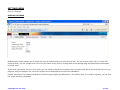
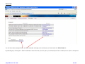
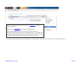
HydroTechnic™
Analytical Design Software Program
User Manual
This user manual is provided only as a guide to using the HydroTechnic™ analytical design software program
and is not intended as nor is it implied to be comprehensive training for siphonic roof drainage design.
©HydroMax Inc. Ltd. 2007
1 of 83
Like all programs, it becomes much easier to use the HydroTechnic™ analytical design software program with practice.
It is the users responsibility to ensure the designs are compliant with local standards, codes and legislation.
GETTING STARTED
First enter www.HydroTechnic.net/login/app into your browser and this screen should be the HydroTechnic login page.
1.
Insert User:
2.
Insert Password:
3.
Click “Login”
©HydroMax Inc. Ltd. 2007
2 of 83
This takes you onto the disclaimer sign in page.
©HydroMax Inc. Ltd. 2007
3 of 83
After you have read and agree to the terms of use policy and wish to continue, at the bottom of the page, click “I accept”
©HydroMax Inc. Ltd. 2007
4 of 83
SETTINGS MENU
Click on “Settings”
DISPLAY SETTINGS
Measurement Locale enables you to select the units of measurement you wish to work with. You can choose metric (SI) or inches (US)
and click Save. You can change from one unit to the other at any time by coming back to the settings page and selecting the alternative
unit and “save”.
If you have input prices into the “Price Lists” you can select to display the contract price by selecting the above box and click save. As you
progress with your designs, the cost of the system will be displayed at the top of the calculation.
Display Pipe Sizes? If checked and saved this will show pipe lengths and diameters in the drawing view. For complex systems, you will find
the screen becomes congested.
©HydroMax Inc. Ltd. 2007
5 of 83
Me
If you click on “Me”, your company name and Logo (if uploaded) will appear together with notice of how many days to go before you will
need to request extension of your license. Also displayed is the number of users on line from your organization and the number of licensed
seats registered to your company.
On this screen you can enter “Change Password” to your chosen password. Please take care not to disclose your user name and password
to any other person.
Insert Your Old Password followed by New Password, re-enter new password then press “Save”. This will be your new password for your
next log-in.
©HydroMax Inc. Ltd. 2007
6 of 83
Hydraulic Parameters
This section lists the pre-set hydraulic parameters which must be met in order to design a system to get the “PASS” result.
There is only one user setting and that is the Discharge Velocity. This should be set by the user to meet the discharge velocity
requirements of the project – in other words this setting is to identify the velocity at the point where the siphonic system stops and
connects to gravity drainage to ensure the velocities are acceptable to the receiving pipe or chamber/manhole etc.
The settings are displayed in the units of measurement previously set.
©HydroMax Inc. Ltd. 2007
7 of 83
Price Lists
You will have been assigned Drain and Pipe materials to design with and these are listed under the Price Lists tab.
By selecting any of the pipe or drains materials in blue font color you will open your selected price list to enable you to input or edit prices.
©HydroMax Inc. Ltd. 2007
8 of 83
You can enter any price you wish – these price lists are for your use and the prices will be used to calculate totals within the material bill
of materials section or for display on the calculation screen.
You can choose your buying price, selling price, list price, price including labor and profit – it really is your own choice.
Please Note: These settings are for your Company – not just you as an individual user.
©HydroMax Inc. Ltd. 2007
9 of 83
Once you have input the prices you require, press save. These prices are then in use for your company.
Logo
The final part of the Settings menu is “Logo”.
This enables you to upload your own company logo for a more professional output to your printed information. Just open the browse
button and select the logo you wish to display from your files.
©HydroMax Inc. Ltd. 2007
10 of 83
FILES MENU
Click on “Files” tab
You have the ability to create New File or a New Folder. It is recommended to create and use a directory system to manage your files.
Insert your chosen Folder Name and Select “New Folder”. In this case input Project Demo #07 007.
After selecting “New Folder” the directory appears on screen.
Open “Project Demo Folder #07 007” then Insert your chosen filename (07 007 RWP 01 rev 0) into this box and click “New File”
This opens up the “Drawing window”. See page 11
©HydroMax Inc. Ltd. 2007
11 of 83
Files Menu
The Files menu section enables you to cut & paste into other directories, copy & paste into other directories Erase files, assign permissions
and generate collated bills of materials from several systems designs.
“Go to Home Folder” takes you to your highest level folder.
©HydroMax Inc. Ltd. 2007
12 of 83
To Cut, Copy or Erase Files or Folders you must first check the box under the “Select” title
In this example, we have
selected the Folder “2003” by
clicking in the box.
You can select multiple files or
folders by checking the relevant
box.
We can now choose Cut, Copy, or Delete. You can choose individual Files, Individual Folders or multiples of Files or Folders.
“Cut” - removes the selected files or folders and places them on the clipboard for “Pasting” into a different location.
“Copy” - retains the files or folders in this location and also places them on the clipboard for “Pasting” into a different location.
“Delete” - removes the selected files or folders. If selected you are asked the question – Are you sure you want to delete?
If you select “Delete” the file or folder is
permanently deleted. If you press “Cancel”
the file or folder is reinstated to its
location.
Please note: A folder must be empty
before the program allows deletion of a
Folder.
©HydroMax Inc. Ltd. 2007
13 of 83
“Paste” – Once File(s) or Folder(s) have been selected, the Paste icon becomes active. You can then select the directory Folder of your
choice and click the “Paste” icon and the files will be taken from the clipboard and entered into your chosen folder.
“Paste” icon
“Cancel Action” icon
“Cancel Action” – If any Files or Folders have been copied or cut, clicking the “Cancel Action” icon will cancel the copy or cut and retain
the files or folders in their original location.
Sharing Files/Folder
HydroTechnic™ offers you the ability to share your files or folders with other registered users from other companies. For example if an
architect and engineering firm both wish to review the HydroTechnic™ designs, user from Company A can give permission to a user in
Company B to either Read Only or Read & Write.
If you wish to share a file or folder you
select “Read” if the Company B user is only
getting the ability to see the file and check
“Read/Write” if the Company B user can
make changes and write / save changes.
Then click the Green Tick icon for “Update
Permissions.
“Update Permissions”
©HydroMax Inc. Ltd. 2007
14 of 83
Clicking “Update Permissions” will bring up “Read Link” under the
Sharing URL title.
Right click on “Read Link” then select “Copy Shortcut”
You can then paste the URL into an e-mail or fax. User from
Company B user can then login to use HydroTechnic™ and paste this
into their browser address bar which will give them access to the files
or folders which they have been given permission to access.
To remove the sharing rights you would select the “Private” button and select the green tick to “Update Permissions”
©HydroMax Inc. Ltd. 2007
15 of 83
Collated “Bills of Materials”
Generate Bill of Materials for Checked Files
To generate a collated bill of materials for several systems, select the files required (in the same way as described above for cut, copy or
delete) then click the Generate Bill of Materials for Checked Files Icon. This will automatically produce a collated bill of materials and the
files included will appear on the bill of materials.
©HydroMax Inc. Ltd. 2007
16 of 83
DRAWING
Inputting Drawing
As with any program which is new to you, you may find that you can do something wrong.
We would therefore recommend that you save at regular intervals.
Please note that if you click on the ‘Clear Drawing’ icon at any time, you can click ‘Undo’ to bring the drawing back.
We will input the data as shown on schematic drawing on page 17 below. To start inputting any section of pipe you need to click on the
node point from where you want to start adding pipe. With a new system this will be the discharge. Click on the Discharge node to make it
red and “active”.
The Default pipe material and diameter will be set to CI no-hub 3” or HDPE 75mm depending on your supply company location.
If you want to build with an alternative pipe material select using the drop down menu. If you select an alternative material, you will need
to input a diameter – we suggest using 3” or 75mm because we will use the program to “First-Size” the system after the drawing is
complete.
©HydroMax Inc. Ltd. 2007
17 of 83
Worked Example – (US Customary Units of Measurement)
Please note that sections are separated only for design
purposes – they are not necessarily pipe joints.
They are used because Pipe diameters can only change
between these node points.
As such, additional node points helps with the hydraulic
design.
©HydroMax Inc. Ltd. 2007
18 of 83
Drawing Screen
This is the main operational area of the program. It has two main regions:
Graphics screen in which the system is built and edited
Data screen in which system components are listed and can be edited.
Frames will pop-up to the right of this window giving warning messages or information relevant to the operation
being performed.
When using the Graphics screen
The pipe system is shown as a series of pipes and nodes.
Build and edit functions can be performed by clicking on the nodes or pipes with the mouse.
XYZ
With a new screen a single node representing the discharge is displayed. The system is built away from this node
with pipes running in x, y and z directions as shown by the image on the screen.
When using the SI metric units of measurement, we use metres as the unit of measurement. Therefore 1 metre
and 250 millimetres is entered as 1.25.
When using US customary units of measurement (feet/inches), insert pipe lengths using the feet (’) symbol. There
is no need to insert the inches (”) symbol. E.g. input 6’ 6 for a length of 6 feet, 6 inches.
If your input length is less than one foot you may enter only the inches e.g. 8 will enter 8 inches.
©HydroMax Inc. Ltd. 2007
19 of 83
The information is input into the program in an
isometric schematic format.
Select ‘+’, ‘0’ or ‘-’ for X and Y direction and
either ‘0’ or ‘+’ for the Z direction.
The drawing starts at the discharge point and
builds up to the furthest roof drain.
The Direction Arrow Changes Red indicating the
direction selected.
+ X is drawing towards the top right of the screen. – X is drawing towards the bottom left of the screen.
+ Y is drawing towards the bottom right of the screen. – Y is drawing towards the top left of the screen.
+ Z is drawing vertically upwards
Moving about the screen
The network can be moved across the screen
by clicking on one of four arrows
©HydroMax Inc. Ltd. 2007
20 of 83
Zooming into the drawing
Zoom in
Zooms in to the middle of the screen
Zoom out
Zooms out from the middle of the screen
Zoom to node
If a node is clicked it will turn red. The zoom to node button will then zoom in to this node. The button can be used
repeatedly to obtain a closer view.
Fit to page
The whole system will be displayed on the screen
Project Data
The Project Data icon opens a frame to the right of the screen in which information about the project should
be entered. Information entered on this screen appears on the output, the project and system being on the header
for every sheet.
Data fields are:
1.
2.
3.
4.
5.
6.
7.
Client
Project
System
Downpipe Location
Reference No.
Date (defaults to today)
Designer
PLEASE NOTE: These Fields need to be completed and saved to make the Overview Report, Bills of Materials and
Fabrication Sheets become active (Fabrication Sheets only for HydroMax™ HDPE pipework)
©HydroMax Inc. Ltd. 2007
21 of 83
Worked Example
Cast iron (CI no-hub) pipework will be used for this example.
The designer “draws” the pipe routing required to collect the water from the roof drains and run through the building to the discharge
point which is the termination or break of the siphonic action.
As noted above, the drawing starts at the Discharge point and we recommend working towards the farthest roof drain. In this example
scheme above this is Roof Drain 1.
Positioning of Node Points
It is important to know that pipe diameters can only be changed between two or more node points.
Every change of direction and branch/junction is assigned a node point.
Please note: the program differentiates the straight through
section of the branch from the 45 degree ‘Wye’ section to enable
easy recognition for the user to determine orientation at branch
connection.
The ‘Wye’ section is designated ‘branch’
The straight through section is designated ‘junction’
To enable the designer more flexibility in system sizing, we recommend building ‘extra’ node points into the following
areas:
The vertical downpipe (stack) – use at least 2 node points.
The section of pipe connecting the roof drain into the horizontal carrier pipe is called the tail-pipe.
It is significantly beneficial to have 2 node points on both vertical and horizontal sections of the tail-pipe.
Split every horizontal section into 2 sections (between any change of direction or between branches).
The active node is always red.
There is an unlimited ‘Undo’ function. If you use the ‘Undo’ there will be no active node.
To restart building the drawing after an undo function, click on the node from which you wish to build from. It will become RED and
active.
©HydroMax Inc. Ltd. 2007
22 of 83
NOTE:
At the start of the drawing, the object type will default to Pipe as
you cannot have a Drain at the Discharge
We need to input a length of 12 feet in the + X direction.
Start by selecting +X.
For the 12’ length required, we will use 2 sections of 6’.
This meets the design help of 2 sections per horizontal length.
Click ‘Add’ or press the Return/Enter key to enter this length.
©HydroMax Inc. Ltd. 2007
23 of 83
Center to Center Dimensions
Within the HydroTechnic™ program you
should insert center to center dimensions
whether these dimensions be from
centers of bend to branch or center of
bend to bend or center of branch to
branch.
To start drawing the vertical section, first select ‘0’ for X
Then ‘+’ for Z.
Input the length 2’ 6
Click ‘Add’ or the press the Return key to enter this length.
©HydroMax Inc. Ltd. 2007
24 of 83
When a 45 degree angle is required (e.g. for an off-set), two directions will be selected. In this case + X and + Z.
Enter 8 (for 8 inches) and ‘Add’ or press the Return key.
©HydroMax Inc. Ltd. 2007
25 of 83
By selecting only ‘+’ Z, complete the input of the vertical section with two sections of 10’ 0” and one section of 2’ 4”.
©HydroMax Inc. Ltd. 2007
26 of 83
To draw in the horizontal sections, change direction to –Y and build two sections at 2’ 0”. Then continue in same direction with two
sections at 33’ and one at 20’.
Change direction to +X and build two sections at 10’ and four sections at 20’.
As this pipe run is the same as the pipe at the other side, we can copy this section to save time.
1. Click on the section of pipe at the
end of the horizontal carrier pipe run.
2. Hold down “Shift key” and Click
on the section of pipe at the
beginning of the horizontal carrier
pipe run. The selected pipe sections
become RED
With the whole pipe run to be copied being RED
in color. The copy button will become active.
3. Left click “Copy”
©HydroMax Inc. Ltd. 2007
27 of 83
Live Paste Button
4. Next, click on the branch node point where you wish to paste
the copied pipe run.
As the active node, this will become RED and the Paste button
will become live.
5. Click paste button to paste a replica pipe run.
If necessary, click “Fit to Page” icon to show the full drawing.
©HydroMax Inc. Ltd. 2007
28 of 83
We should now input the tail-pipes and roof drains. Click on the end of the first drawn horizontal run to make the node active.
The node becomes RED active and the data input area reappears as shown below.
Choose the –Y direction and input two sections of 3’ 3”.
Then Select + Z direction and input two sections of 1’ 4”.
We are now ready to input the first roof drain. Click on the Object button “Drain”
©HydroMax Inc. Ltd. 2007
29 of 83
SEE DRAIN SELECTION ON PAGE 30
This is just an example, therefore the choice of drain is not important. We will use the WADE-HydroMax® WH-300 without dome.
Once selected, click “Add”.
Depending on your region, you will have a
choice of drains.
The North American markets have the
WADE-HydroMax® Range of IAPMO listed
cast-iron drains with WH prefix.
Other International markets will have
metric specification drains in either 75mm
or 125mm Spigot size in a range of
different materials to suit your roof type.
Select the required roof drain and click “Add”. The drain is added to the drawing.
©HydroMax Inc. Ltd. 2007
30 of 83
We can now copy this tail pipe and roof drain for the other 2 drains connecting to the first carrier pipe run which have the same
configuration.
If you wish to zoom in, Click on any node within the tail-pipe (the bottom bend is best selection). Click “Zoom to node”.
Select the sections of pipe required to be copied by clicking on the roof drain, hold down shift key and select the first section of horizontal
tail pipe.
Select the sections of pipe required to be copied by
1. Click on the roof drain.
2. Hold down shift key and Click on the first
section of horizontal tail pipe. The section
selected becomes highlighted RED.
3. Click the “Copy” icon to copy all the components
highlighted.
If you have zoomed in, click the “Fit to Page” icon.
You can now Paste the copied section to the branch positions required.
©HydroMax Inc. Ltd. 2007
31 of 83
To Paste the copied section of tail pipe with roof drain
onto these two branch locations
4. Click onto the middle tail pipe branch node.
5. Click the Paste icon.
6. Click on the third drain branch connection.
7. Click the Paste icon.
The copied items remain on the clipboard until something else has been selected for the Cut, Copy or Delete function.
©HydroMax Inc. Ltd. 2007
32 of 83
We now need to input the final
three roof drains.
First, make the end of the second
carrier pipe run active by clicking
the end node.
To input the tail pipes required we will have to ensure the Object selected is ‘Pipe’ by selecting the ‘Pipe’ button.
Select the required pipe material (in this case CI no-hub) followed by selecting the diameter as 3”.
We will now input the tail-pipe by selecting the +Y direction and input two sections of 3’ 3”. Select the + Z direction and input two
sections of 1’ 4”.
Finally, we then input a roof drain as described in page 33 above. After this drain is added the tail-pipe and roof drain can again be copied
and pasted at the two final branches to complete the drawing.
©HydroMax Inc. Ltd. 2007
33 of 83
A feature of the HydroTechnic™
analytical design program is the
First-Size function.
This assigns pipe diameters and
performs the hydraulic calculation.
The program attempts to find pipe
diameters which will be close to those
required to make the system operate
within its necessary parameters.
The larger the system and associated
diameters become, the more complex
this becomes and you will need to
revert to manual calculations.
Click on the First-Size icon.
©HydroMax Inc. Ltd. 2007
34 of 83
The Roof Drain ‘Assign Flow Rates’ box appears. There are 6 drains on this system and so 6 numbered boxes appear. If you move the
cursor over the numbered outlet (drains) the display will turn the corresponding roof drain red (this is or great benefit when you have
complex systems with multiple roof drains and different flow rates to ensure you input the correctly assigned flow.)
We will input the assigned flow of 366 gpm (Gallons per minute) in the Outlet (roof drain) #1 box. Then check the ‘(Make same:
because all roof drains on this system have the same flow rates and this saves repeatedly entering the same data.
)’ box
All drains will now have their assigned flow of 366 gpm and we click “Calculate”.
If you make a mistake and want to go back you can use the Cancel button.
©HydroMax Inc. Ltd. 2007
35 of 83
Most calculations which are complex will require the system designer to edit pipe sizes to achieve the optimum solution.
With this example, we achieve all the necessary parameters EXCEPT – tail pressures out of balance setting (1.509 ft) and therefore obtain
a FAIL.
With this calculation result we need to edit the tail pipes and there may be a means to achieve the necessary solution using smaller pipe
diameters.
©HydroMax Inc. Ltd. 2007
36 of 83
We shall therefore click on the tabular view window to edit the pipework.
We can see the tabular view has the discharge point at the top of the list.
The Parameters to be met are can be viewed if you go to >Settings>Hydraulic Parameters.
Please Note: If you ever require a change to any of the pre-set parameters please contact [email protected] :
©HydroMax Inc. Ltd. 2007
37 of 83
Tabular View
Column 1 numbers each item within the system
Column 2 describes each item.
The items types are as follows:
Discharge: This is the point where siphonic action is broken through introduction of air. This can be connection to a ventilated gravity
drain, a catchpit / chamber or to Air (atmosphere).
Pipe:
45° bend (⅛ bend);
90° radius bend (¼ bend);
90° elbow (¼ bend with tighter but still swept radius);
Junction: this is the connection from the straight run into a 45° ‘WYE’ Branch;
Branch: this is the connection from the 45° connection into a 45° ‘WYE’ Branch;
Expansion: This is an increaser to change the pipe to a greater diameter;
Reducer: This is an reducer to change the pipe to a smaller diameter;
Roof Drain: Details the selected drain in each location.
Column 3 denotes the pipe material type
Column 4 details the selected diameter for each given element.
Column 5 gives the overall length of the pipe sections
Column 6 notes any vertical height within the pipe section.
Column 7 headed xyz denotes the pipe direction as drawn within the Graphics screen.
Column 8 is the total flow rate within each pipe section.
Column 9 notes the velocity with the element
Column 10 is the calculated pressure headloss for the element
Column 11 is the actual pressure in that section.
An additional feature is the noting of the velocity at the discharge point denoted Discharge velocity: This is set at a maximum of 18.045
feet per second. This is variable user-setting chosen by the user (within the maximum and minimum velocity settings) enabling the user
to set an appropriate and compatible velocity for the connection from siphonic flow to gravity drain, catchpit or air (atmosphere).
©HydroMax Inc. Ltd. 2007
38 of 83
Tabular View
As shown on page 39, the data contained in the tabular view is initially displayed with item 0 being the discharge point and each
component being consecutively numbered initially to the Roof Drain Outlet 1. Then carrying on with numbering from the branch
connection to roof drain 2, then roof drain 3 and so on until the last roof drain, in this case roof drain 6.
However, if you choose to view only the path of a single roof drain, move your curser over the list of tails and the tail which the cursor is
over goes YELLOW. Click on the tail section you wish to view and the view will display a full list of all components from the selected roof
drain down to the discharge point.
Select Tail # 2.
If you want to revert to the full list of components, select the “Show All Elements” button.
Within the tabular view, you can move your cursor over any element and it will highlight in a gray color. If you left click it will change to a
pink color denoting it has been selected for editing. Holding the left mouse button down, you can scroll up or down to select multiple
elements for editing. If you highlight an element you want to deselect, just move your cursor over the element and left-click to de-select.
©HydroMax Inc. Ltd. 2007
39 of 83
Similarly if you want to de-select a group of elements, hold down your left click button whilst running your cursor over the elements.
Once you have edited any section you will have two calculation results displayed – Previous and Current.
The reason for displaying the Previous is so that you can compare the results to see if the edit has achieved your objective. If it has not
obtained the result you were looking for, you can use the “undo” function to revert to the previous position.
You will notice that the some combined pipe lengths are adjusted by the program by moving node points – the program does not alter the
total length or height- it only moves node points to help with the design. The exception to this is at the roof drain. The program takes off
the vertical height of the actual drain which is encoded into the software.
©HydroMax Inc. Ltd. 2007
40 of 83
Editing a Single Section.
When editing a single section you have the following Edit options:
1. Change Pipe Material (or drain type)
(Note: If you change a roof drain you need to re-enter the gpm
inflow at the calculate section)
2. Change Diameter
3. Change Length (only if a pipe is the selected object) –
This feature is normally used for fine balancing of tail pipes.
You can ‘move’ a node point where there is a change in pipe
diameter within a length which is in two or more sections. For
this, you leave the “Retain Overall Length” box checked.
If you are looking to change the actual overall length, you need
to uncheck the “Retain Overall Length” box and this will change
the section length without changing any other section.
Editing Multiple Sections
When editing a multiple sections you can only change the material and/or the diameter.
©HydroMax Inc. Ltd. 2007
41 of 83
Editing this Worked Example.
Although the First-size resulted in a ‘PASS’, we shall seek an alternative solution without warnings and using smaller pipe diameters.
©HydroMax Inc. Ltd. 2007
42 of 83
We will try to reduce the amount of 10” pipe required. Click on item 0 (Discharge), Hold left mouse button and Scroll through to item 16
(Junction). This will highlight all sections from 0 through to 16. Click Edit Selection.
Choose 8” diameter from the drop down list and click “Save”. All items from 0 to 16 are now 8” diameter.
You will now see two sets of results - Previous and Current. We have a RED “FAIL” and the section(s) failing are in highlighted RED.
There is still an Out of Balance Fail and Tail Pressure Fail. Tail 6 has a pressure reserve of -4.111 feet. A negative pressure reserve of
between 0 and -3.281ft is required. A negative value greater than -3.281 ft means the tail pipe has too much capacity and is oversized.
A positive tail pipe reserve pressure means that the tail pipe is undersized.
©HydroMax Inc. Ltd. 2007
43 of 83
There are several ways to edit systems. With this example we are going to deliberately demonstrate various ways of editing with moves to
highlight the flexibility in use. We will therefore create “FAILS” to show how to edit and undo when results are not as required.
Some General Rules of Thumb for designing are as follows:
Overcapacity (a negative pressure reserve greater than -3.281ft) means your diameters are too big. However, due to some piping
materials only being available in limited diameters, reducing a diameter may cause too much of a restriction or too high velocity.
Under capacity (a positive pressure reserve) means your diameters are too small. However, increasing a diameter may result in too low a
velocity or may result in increased negative pressure (especially on the vertical stack).
If you have over capacity, another means to add restriction is through rerouting the pipework to give added frictional losses from the
extra pipework length and/or additional bends.
For this example we will also demonstrate editing of this system in both tabular view and the drawing view.
The first attempt to add a restriction would normally be through choosing one pipe diameter smaller for a section of pipework. In this
case, we only need a small restriction so we will attempt to reduce a section of the tailpipe from 3” to 2”.
We cannot reduce diameter in the direction of flow on a horizontal section of pipe. We cannot increase diameter in the direction of flow in
the vertical section of pipe.
In this case we only have two options. Reduce all of the vertical tailpipe section or reduce only the bottom part of the vertical section (this
is why we split the tailpipe sections into two parts on both vertical and horizontal plains.)
As we only need a small restriction, we shall try to edit the bottom section of the vertical tail pipe by one diameter from 3” to 2”.
At the same time ,we shall also reduce the length of this section to 6” to limit the restriction. To do so while keeping the overall length
intact, we need to leave the “Retain Overall Length” box ticked.
Select drain #6. The tabular view will show only the elements from roof drain 6 down to discharge point.
©HydroMax Inc. Ltd. 2007
44 of 83
Click line item 87 to highlight it pink. Click “Edit Selection”.
Change Diameter to 2”
Change Length to 6”
Click Save
The result is such that 2” pipe is too small for the volume of water flow and results in the pipe being under capacity. Additionally, the
velocities are too high.
The whole effect is the system fails in three areas:
1. Out of balance
2. Velocities too high and
3. the pressure reserves noted for tail #6 show a positive residual head which means the drain is not taking the target inflow.
©HydroMax Inc. Ltd. 2007
45 of 83
This edit is not what we want so we click “undo”.
Our next best option to edit this design is to create a restriction to tail #6 through adding some pipework and bends to the tail section.
We do this in the drawing (graphic) View .
Click on the drawing view
©HydroMax Inc. Ltd. 2007
then click the node at the bottom of the vertical tail for roof drain #6 then click “Zoom to Node”.
46 of 83
Click on the node midpoint of the horizontal leg. Select 3”, select + X,
input 1’ and select Insert (selecting Add would create a new pipe branch).
Click on the node at the bottom of the vertical section.
Select 3”, select - X, input 1’ and select Insert to bring the roof drain
back into position.
©HydroMax Inc. Ltd. 2007
47 of 83
Then select “Calculate” (IMPORTANT – DO NOT CHOOSE FIRST SIZE).
This has resulted in too much of a restriction as we now have undercapacity indicated by a positive figure for the tail pressure reserve.
©HydroMax Inc. Ltd. 2007
48 of 83
We will alleviate this by changing the section of branch pipe from the carrier pipe to 4”.
In the graphic view, left click on the pipe section and it will turn RED. (You can also edit this change in the Tabular View)
Change diameter to 4” and press Save.
This results in the tailpipe again being oversized.
There is also a Warning:
A reduction in size of the lateral at 85 is not recommended because it
may cause a blockage. A
blockage.
•
This is because the pipe has been increased but the wye branch and
45 degree bend are still 3”
Select Undo
Revert to the tabular view and select tail pipe #6.
©HydroMax Inc. Ltd. 2007
49 of 83
Select line items 82 and 83. This is the Wye branch from the main carrier pipe and the 45 degree bend connecting to the branch. We will
give the system just a little bit less restriction by increasing the diameter of these two components to 4” diameter.
Select 4” from the diameter drop down menu and click “Save”.
©HydroMax Inc. Ltd. 2007
50 of 83
All Parameters are now met and we have a satisfactory “PASS” without any Warnings.
©HydroMax Inc. Ltd. 2007
51 of 83
Show the Drawing Information icon
Prior to printing out any of the System Design data, ensure that the project and client information is completed.
Open the dialogue box by clicking on “Show the drawing information” icon. Complete the information and click “Save”.
After saving, The Overview Report and Bill of Materials icons now become live.
©HydroMax Inc. Ltd. 2007
52 of 83
Overview Report
– Summary of Hydraulic Calculations
Click on Overview Report and you obtain a Summary detailing the Project Information (which the user has input) and the hydraulic
calculations.
©HydroMax Inc. Ltd. 2007
53 of 83
The Summary can be printed to your local printer or printed to create a PDF file (if you have a PDF writer).
Alternatively, as the program uses HTML format, you can right click, choose select all, right click again and choose copy and the Summary
can then be pasted into any program such as Word, excel, etc.
©HydroMax Inc. Ltd. 2007
54 of 83
Bill of Materials icon
– Parts List
If you choose the “Drawing” tab, you can then select Bill of Materials icon to give you a full list of the materials required for the system.
Please note: If you have input prices into your price lists as noted in Page 55, your bill of materials will provide a total
value.
©HydroMax Inc. Ltd. 2007
55 of 83
Export Fabsheet icon
There is an icon to Export Fabsheet but this function is only for use with HydroMax™ HDPE pipe designs. If the design is with HDPE, you
select the icon and a PDF file is written to your directory which can be downloaded and shows pre-fabrication drawings in metric 6 metre
lengths.
Design Disposable Head Adjustment
If the discharge pipe may be submerged (refer to ASPE Plumbing and Engineering Design Standard 45 – Siphonic Roof Drainage 4.7) it
may be necessary to make an adjustment to account for a restricted (submerged discharge).
We have made the function simple within HydroTechnic™ with the Design Disposable Head Adjustment tool. Click on the icon and the
following tool becomes available.
Input the height of restrictive discharge then ‘save’
Adjust pipe diameters if necessary to meet a ‘PASS’ under the new Disposable Head height.
©HydroMax Inc. Ltd. 2007
56 of 83
Amending Designs.
Adding a pipe offset around an obstruction.
Highlight the section where offset is required by clicking on the pipe. Then select ‘Delete the selected pipes’ icon.
The selected section has been deleted.
©HydroMax Inc. Ltd. 2007
57 of 83
Click on node to make it active.
Select pipe material (CI no-hub for this example).
Select diameter (8” as per section removed)
Select direction and input length.
Select ‘Add’.
©HydroMax Inc. Ltd. 2007
58 of 83
The 2’ long section of 8” CI no-hub pipe is added.
Now add 5’ of + Y then offset 2’ back in the
+X, -Y direction.
©HydroMax Inc. Ltd. 2007
59 of 83
Linking Sections together
Hold shift key and select second node point.
The “connect the two selected end nodes”
icon becomes active.
Select this button and the two ends are joined.
Once the sections are joined, press calculate
still a ‘PASS’.
(not First size). The new hydraulic results are now displayed. In this case the result is
If a ‘FAIL’ is obtained, you will have to edit the diameters to meet all the hydraulic parameters.
©HydroMax Inc. Ltd. 2007
60 of 83
The additional bends create frictional losses which have sent the tail pressures outside of the balance permitted (1.509 ft).
When looking at the two extremes in the tail pressures summary, we can see that tail 3 is closest to zero and tail 5 is farthest.
We need to bring these two pressures closer together and therefore will look at tail 5 first. Click on tabular view than click on tail 5.
©HydroMax Inc. Ltd. 2007
61 of 83
Tail 5 would need reduced in capacity to bring it closer to zero.
As this tail is using 3” pipe and we already know that 2” pipe puts the velocity too high, we should look at Tail 3 to see if this would be
better to edit.
©HydroMax Inc. Ltd. 2007
62 of 83
Tail 3 has all 3” and requires a little bit more capacity to bring the tail pressure closer to Tail 5.
We will change the reducing Wye from an 8” by 3” Wye to an 8” by 4” Wye. Change section 53 to 4”
This has increased the capacity but now tails 1 and 2 have been affected and have both gone closer to zero.
We shall edit both these tails to bring them closer to tail 3.
©HydroMax Inc. Ltd. 2007
63 of 83
Click on Tail 2.
Highlight the 3” 45 elbow at section 46 and change to 4”.
This results in tail 2 being within the permitted balance.
©HydroMax Inc. Ltd. 2007
64 of 83
We now need to edit tail 1 to bring this within the set parameter.
©HydroMax Inc. Ltd. 2007
65 of 83
Click on tail 1 and select section 34 to edit. Change diameter to 6”
This results in a PASS with all parameters being met and the system is within the permitted 1.509 feet out of balance.
©HydroMax Inc. Ltd. 2007
66 of 83
Offsetting a Complete Pipe Run
If the whole pipe run needs to be moved there are a few
options.
You can extend the pipe as highlighted which was 20’. If the
run had to be 2’ further over you can adjust this length to
22’ thus pushing everything over 2’.
You would then have to edit each tail pipe to reduce the
horizontal by 2’.
Alternative Offset
Option 2 is to select the node as shown.
The Pipe Input dialogue box opens up.
Select the pipe material, diameter, offset direction,
input the hypotenuse length 2’ 9.5 and click ‘Insert’.
©HydroMax Inc. Ltd. 2007
67 of 83
The offset is input. You now need to adjust the tailpipe length. The tail pipe horizontal section was 3’ 3”.
We have offset 2’ so click on the tail pipe section and
change length to 1’ 3”.
IMPORTANT: You must uncheck the “Retain
Overall Length” to make the adjustment.
After the tail lengths are adjusted
you need to press calculate
Again, we have a ‘PASS’.
If a ‘FAIL’ is obtained, you will have
to edit the diameters to meet all
the hydraulic parameters.
©HydroMax Inc. Ltd. 2007
68 of 83
Flow Balancing
Many designs are completed with assigned flows and the heads at the roof drains are allowed to be out of balance within an allowable
range. In a completely Flat roof or Level Gutter this will not occur, the flows will adjust themselves so that the out of balance head at each
roof drains is zero.
Clicking this button will adjust the flows until the heads at each roof drains are as close to zero as possible, if this is not achieved first time
the button is clicked repeated clicking may produce better results. Once the flow balance is complete the implications of the required flow
re-distribution can then be evaluated by the user to see if they are realistically possible. Pressures in the pipework will also be recalculated
and for systems that are close to the design limit this may highlight the risk of unacceptable negative pressures.
After this check the regularly assigned design flow condition can be restored using the undo button if desired.
Drain Selection
For drain selection in the North American market, the Cast Iron WADE-HydroMax® drains are the available options.
There are 4 drain sizes available – 3”, 4”, 5” and 6”. All sizes are available as Primary or Overflow Roof Drains.
The 3” and 4” Drains are also available as Deck Drains.
Resistance ‘K’ Factors and Recommended Flows are as follows:
C.I. No-Hub
Outlet
3”
4”
5”
6”
K factor
0.12
0.08
0.04
0.04
Minimum GPM
Inflow
23
75
120
160
Maximum GPM
Inflow
415
750
1300
180
The following accessories are available for each drain:
Leafguard
Debris Guard
Underdeck Clamps
Bearing Pans
Bespoke accessories can be made to order such as gravel guards, etc.
©HydroMax Inc. Ltd. 2007
69 of 83
©HydroMax Inc. Ltd. 2007
70 of 83
©HydroMax Inc. Ltd. 2007
71 of 83
©HydroMax Inc. Ltd. 2007
72 of 83
©HydroMax Inc. Ltd. 2007
73 of 83
©HydroMax Inc. Ltd. 2007
74 of 83
WADE-HYDROMAX® Flow Performance
WH-600 (Primary Roof Drain)
&
WH-601 (Overflow Roof Drain)
6" dia Outlet
5
5
4
4
3
With leafguard
No leafguard
2
1
0
0
Water Depth (Inches)
Water Depth (Inches)
6" dia Outlet
3
No leafguard
With leafguard
2
1
500
1000
1500
Flow Rate (GPM)
Figure 6.1 - Rating curve (GPM format)
©HydroMax Inc. Ltd. 2007
2000
0
0
1
2
3
4
5
Flow Rate (cu.ft/sec)
Figure 6.2 - Rating curve (ft3/s format)
75 of 83
WADE-HYDROMAX® Flow Performance
WH-500 (Primary Roof Drain)
&
WH-501 (Overflow Roof Drain)
5" dia Outlet
5
5
4
4
3
With Leafguard
No Leafguard
2
1
0
0
Water Depth (Inches)
Water Depth (Inches)
5" dia Outlet
3
No Leafguard
With Leafguard
2
1
500
1000
Flow Rate (GPM)
Figure 5.1 - Rating curve (GPM format)
©HydroMax Inc. Ltd. 2007
1500
0
0
1
2
3
Flow Rate (cu.ft/sec)
Figure 5.2 - Rating curve (ft3/s format)
76 of 83
WADE-HYDROMAX® Flow Performance
WH-400 (Primary Roof Drain)
&
WH-401 (Overflow Roof Drain)
4" dia outlet
4
4
3
3
Water depth (inches)
Water depth (inches)
4" dia outlet
2
No leafgaurd
With leafguard
1
0
0
2
With leafguard
No leafgaurd
1
200
400
600
Flow rate (gpm)
Figure 4.1 - Rating curve (GPM format)
©HydroMax Inc. Ltd. 2007
800
0
0
0.5
1.0
1.5
2.0
Flow rate (cu.ft/sec)
Figure 4.2 - Rating curve (ft3/s format)
77 of 83
WADE-HYDROMAX® Flow Performance
WH-300 (Primary Roof Drain)
&
WH-301 (Overflow Roof Drain)
3" dia Outlet
3
3
2
2
Water Depth (Inches)
Water Depth (Inches)
3" dia Outlet
1
0
0
1
No Leafguard
With leafguard
No Leafguard
With leafguard
100
200
300
400
Flow Rate (GPM)
Figure 1, Rating curve (GPM format)
©HydroMax Inc. Ltd. 2007
0
0
0.2
0.4
0.6
0.8
1.0
Flow Rate (cu.ft/sec)
Figure 2, Rating curve (ft3/s format)
78 of 83
General Tips
We strongly recommend following ASPE Technical Design And Engineering Standard 45 – Siphonic Roof Drainage
The WADE-HydroMax® HydroTechnic™ software program is a tool used to calculate the hydraulics within a piping system and identify the
pipe diameters required for a system to perform properly.
Before using the HydroTechnic™ pipe sizing program it is necessary for the design engineer to work through the following steps.
1.
2.
3.
4.
5.
6.
7.
8.
Determine the design rainfall intensity rate.
Identify and calculate roof areas.
Determine quantity and location of roof drains.
Calculate individual roof drain catchment areas.
Calculate inflow to each roof drain (catchment area x rainfall rate).
Identify discharge location (break to gravity flow or collection tank)
Determine required pipe routing to collect from the roof drains and run to the discharge point.
Draw a schematic drawing with all directional and pipe length information.
Following the completion of the above steps, the design engineer can then use the HydroTechnic™ Analytical Design Program as described
above.
Design Parameters which must be met to achieve a system which works:1. Minimum pressure = -26.247 feet water column (-8 mwc)
2. Minimum velocity = 2.625 feet per second (0.8 m/s) on Horizontal pipework – 7.218 feet per second on vertical stack
3. Maximum out of balance = 3.281 feet wc (1 m water) or 10% of Design Head – whichever is lower.
4. Maximum Residual Head = 3.281 feet wc (1 mwc)
5. Maximum velocity = 26.247 feet per second (8 m/s)
6. Stack Exit Velocity – Default Set at 19.685 ft/s
(Adjustable User setting for compatibility with gravity break connection)
7. Maximum fill time = 60 seconds
©HydroMax Inc. Ltd. 2007
79 of 83
Reasons for the Design Parameters
1. Minimum pressure = -26.247 feet wc
What if pressure drops below the minimum pressure setting?
•
Risk of Cavitation (air coming out of suspension)
•
Risk of Pipe collapse (implosion)
2. Minimum velocity = 2.625 feet per second (0.8 m/sec) on Horizontal pipework – 7.218 feet per second on vertical stack
What if velocities are lower?
•
Risk of Sedimentation
•
Poor priming response
3. Maximum out of balance = 3.281 feet water column (1 m/wc)
What if out of balance figures are greater?
•
Risk of air entrainment = break siphonic action
•
Underperformance
©HydroMax Inc. Ltd. 2007
80 of 83
Reasons for the Design Parameters (continued)
4.
5.
Maximum Residual Head – 3.281 feet wc
•
Prevents piping System having too much spare capacity
•
Ensures hydraulic parameters within system are safe even if rainfall exceeds design rate
Maximum velocity = 26.247 feet per second (8 m/sec)
What if velocities are higher?
Risk of Cavitation (air coming out of suspension)with reduction in drainage capacity
Risk of excessive vibration & noise
6. Stack Exit velocity = Default set at 19.685 feet per second (6 m/sec)
This is a changeable user setting to ensure compatibility at the transition break to gravity flow
7. Fill Time 60 Seconds - What is fill time?
Fill time is determined by the program through a calculation of system volume and design rainfall rate. It is necessary to calculate
the fill time to ensure the system primes and operates with siphonic action within 60 seconds even under flash storm (micro storm)
conditions the building.
•
Tail pipes must fill system
•
System must fill in reasonable time to prevent water build-up on roof
•
Large systems need more filling
©HydroMax Inc. Ltd. 2007
81 of 83
Common tactics for achieving a system design ‘PASS’.
First step should be to ensure negative pressures on the vertical section are within the required range.
Negative Pressure must be above -26.247 feet wc.
If negative pressure drops below -26.247 feet wc there are a few tactics which may be adopted. The first attempt should be to reduce the
pipe diameter on the bottom section of the vertical drop pipe. (If you choose to reduce the diameter of the upper section of the vertical
downpipe and have a larger diameter at the lower section, you must insert an offset bend where the pipe diameter increases in the
vertical in the direction of flow.)
Please note: A reduction in diameter in the vertical may result in underperformance in the system as the reduction in diameter will restrict
flow. To counter this, revisit and increase the pipe diameters for the carrier pipe and tail pipes.
If this fails, the other solution is to reduce the height of the siphonic vertical drop pipe and make the transition to gravity flow before you
reach the ground level. If this option is required then it is essential that the transition point is such that the pipe diameter is sized for
traditional gravity flow to cater for the volume of water from the siphonic pipe. Additionally, it is necessary for the gravity pipe to be
ventilated.
Second Step is to work on tail pressures.
If you work on the farthest tail pipe from the vertical drop pipe and then the nearest tail-pipe and ensure they are within
the pressure balance range between 0.00 and -3.281ft, it should be easy to bring the remaining tail pressures into balance.
Tail Pressures – Must be between 0.00 and -3.281ft
Where a tail pressure is showing a positive number it is undersized.
Solution: Increase pipe diameters on the sections of the tail pipe connecting to the drain. You can also increase pipe diameters on the
main carrier pipe and/or the vertical downpipe but this will affect other tail pressures.
Where a tail pressure is showing a negative figure less than -3.281ft the pipe is oversized.
Solution: Decrease pipe diameters on the sections of the tail pipe connecting to the drain. You may also decrease pipe diameters on the
main carrier pipe and/or the vertical downpipe but this will affect other tail pressures.
Flow velocity must be between 2.625 ft/s on horizontal (7.218 ft/s on vertical stack) and 26.7 feet per second.
If flow velocity drops below 2.625 feet per second the pipe is oversized.
Solution: Decrease diameters on the sections of pipe where the velocity is too slow.
If flow velocity is above 26.7 feet per second the pipe is undersized.
Solution: Increase diameters on the sections of pipe where the velocity is too fast.
©HydroMax Inc. Ltd. 2007
82 of 83
Contacts
WADE Specification products
Post Office Box 2027
Tyler, Texas 75710
Tel: (800) 527-8478
Fax: (903) 882-2543
www.hydromax.com
www.wadedrains.com
For Design
Assistance
Contact
For General or
Sales Enquiries
Contact
Jay Stenklyft
Mike Shirley
Office: 800-527-8478
Ext. 2363
Office: 800-527-8478
Ext. 2668
[email protected]
Cell: 903-941-0882
[email protected]
WADE-HYDROMAX Siphonic
Roof Drainage Products
The New Dawn In Drainage
©HydroMax Inc. Ltd. 2007
83 of 83