1
Loop and earth Ohmmeter
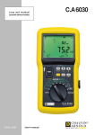
C.A 6456
ENGLISH
User's manual
1
Meaning of the
symbol :
WARNING ! Consult the user manual before using the instrument.
Failure to follow or carry out the instructions in this user manual that are preceded by this symbol may
result in personal injury or damage to the instrument and the installations.
Consult the user manual before using the instrument!
Thank you for purchasing a C.A 6456 loop and earth ohmmeter.
To get the best service from this instrument :
■ read carefully this user's manual,
■ respect the safety precautions
PRECAUTIONS FOR USE
This instrument can be used on category III installations at voltages not exceeding 550V with respect
to earth. Category III meets the reliability and availability requirements of uses on fixed industrial installations
(cf. EN 61010-1 + A2).
■
Never use the C.A 6456 tester on installations having a potential greater than 550V with respect
to earth.
■ Check that none of the input terminals is connected and that the switch is set to OFF before
opening the instrument.
■
Use connection accessories of which the overvoltage category and service voltage are greater than or
equal to those of the measuring instrument (600V, cat. III). Use only accessories that comply with safety
standards (EN 61010-031 and EN 61010-2-032).
■
Do not immerse the C.A 6456 tester!
■
Repairs and metrological verifications must be carried out by approved, qualified personnel.
WARRANTY
Unless otherwise stated, our warranty is valid for twelve months (12 months) following the date on which
the equipment is made available (extract from our General Conditions of Sale, available on request).
2
SOMMAIRE
1
1.1
1.2
1.3
PRESENTATION ...................................................................................................................... 4
Environmental conditions ........................................................................................................... 5
Compliance with standards ........................................................................................................ 5
Power supply ............................................................................................................................. 5
2
DESCRIPTION ......................................................................................................................... 6
3
3.1
3.2
3.3
3.4
3.5
3.6
3.7
3.8
GENERAL USE ........................................................................................................................ 9
Automatic checks ...................................................................................................................... 9
Instrument configuration (SET-UP) ......................................................................................... 10
Compensation of the leads ...................................................................................................... 11
Recording measurement results (MEM) .................................................................................. 13
Recalling recorded values (MR) ............................................................................................... 13
Erasing recorded values .......................................................................................................... 14
Printing measurement results (PRINT) .................................................................................... 15
Printing recorded values (PRINT MEM) .................................................................................. 15
4
4.1
4.2
4.3
4.4
4.5
4.6
MEASUREMENTS ................................................................................................................. 16
Voltage measurement .............................................................................................................. 16
2P and 3P earth measurement ................................................................................................ 21
Earth measurement in live condition (REARTH) ...................................................................... 25
3-wire loop measurement (Z LOOP) ........................................................................................ 32
2-wire loop measurement (Z LINE) .......................................................................................... 35
Current measurement (
) ............................................................................................... 37
5
GLOSSARY ............................................................................................................................ 39
6
6.1
6.2
6.3
6.4
6.5
6.6
6.7
MAINTENANCE ..................................................................................................................... 40
Replacing the batteries ............................................................................................................ 40
Storage .................................................................................................................................... 40
Cleaning .................................................................................................................................. 40
Metrological verification ........................................................................................................... 40
Warranty ................................................................................................................................. 40
Customer service .................................................................................................................... 40
Repair ..................................................................................................................................... 40
7
LIST OF CODED ERRORS .................................................................................................... 41
8
TO ORDER ............................................................................................................................. 41
3
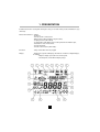
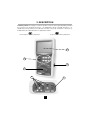
1. PRESENTATION
Portable instrument for testing and checking the safety of new and existing electrical installations (loop
ohmmeter).
Measurement functions :- Voltage,
- Frequency,
- Test of protective conductor, PE,
- Earth resistance with 2 auxiliary rods (3P method)
- Coupling resistance (2P method)
- Loop impedance, with display of the resistive part and of the inductive part,
- Calculation of short-circuit currents,
- Current, with clamp,
- Selective earth resistance (with clamp).
Execution :
- 8-way central switch and 7-key keypad.
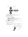
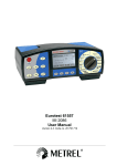
Display :
- Backlit 160-segment LCD display unit with two simultaneous digital displays,
A1 and A2:
- 4 digits to display up to 4,000 measurement points,
- 3 decimal points for the different display ranges.
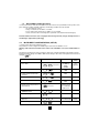
4
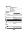
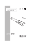
1
position of the phase conductor
12 "object" number for storage
2
auxiliary earth rod detected
13 main display unit A1
3
measurement smoothed for display
14
4
audible buzzer activated
15 measurement with triggering of RCD (full power level)
5
communication in progress (serial link)
16 alarm function activated or display of an alarm threshold
6
battery charge level
17 secondary function activated
7
Auto standby function deactivated
18 type of quantity displayed
8
level of memory use
19 selective measurement
9
reading/recording in memory
10 secondary display unit A2
measurement without triggering of residual current differentials
(RCD) (low power signal)
20 "WARNING" indicator (if it appears, refer to the manual)
21 compensation of measuring cables activated
11 "test" number for storage
1.1
ENVIRONMENTAL CONDITIONS
Temperature :
Service conditions: -10 to +55°C - storage and transport (without batteries): -40 to +70°C.
%RH (without cond.) :
Service conditions: 85% max. - storage and transport (without batteries): 90% max.
Tightness :
IP54 as per standard NF EN 60 529.
1.2
COMPLIANCE WITH STANDARDS
1.2.1
GENERAL
The instrument complies with the following standards:
EN 61010-1,
NF EN 61557 : parts 1, 3, 5 and part 10,
EN 60529,
EN 50102 / UL 94.
1.2.2
SAFETY
The instrument complies with the requirements of standards EN 61010-1 and EN 61557, i.e. :
-
service voltage: 550 V,
-
measurement category: III with double insulation,
-
level of pollution: 2.
1.2.3 ELECTROMAGNETIC COMPATIBILITY
The device is in conformity with standard IEC 61326-1:
Emissions : Requirements on class B equipment.
Immunity : Requirements on equipment used in discontinuous operation on industrial sites.
1.3
POWER SUPPLY
Power supply :
6 LR6 1.5V alkaline batteries; they can be replaced by rechargeable sealed
batteries having a capacity of at least 1,800 mAh.
Battery life :
30 hours or approximately :
- 10,000 loop measurements or under voltage earth measurements
- 1,000 earth measurements (2P/3P) during 30 seconds
- 30,000 voltage or current measurements during 5 seconds.
5
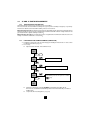
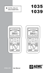
2. DESCRIPTION
Preliminary remarks : Several types of action are possible on each key of the keypad, depending on whether
the user presses the key briefly (short press, < 2s, validated by a beep) or at length (long press, > 2s,
validated by a beep having a tone different from that of the beep emitted for a short press).
In what follows, these different actions are symbolized as follows:
for a short press on the key in question
for a press > 2s on the key in question
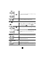
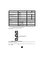
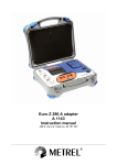
3
2
4
1
5
6
6
1
8 WAY ROTARY SWITCH :
- OFF :
instrument off
- 3P :
earth measurement with 2 auxiliary rods
- 2P :
AC or earth coupling resistance measurement
- REARTH /
:
earth measurement in a live condition, with one auxiliary rod (selective earth
if clamp connected)
- ZLOOP :
loop impedance measurement with 3 wires (high or low current), between
phase (L) and earth (PE)
- ZLINE :
loop impedance measurement with 2 wires (high current only), between two
phases or between phase and neutral
:
current measurement
- SET-UP :
configuration of the instrument
Set the switch to OFF when the instrument is not in use
2 7-KEY KEYPAD :
The functions of the various keys are as follows for all the settings of the switch EXCEPT the SET-UP
position (see § 3.2).
Touche 2nd :
2nd + press on other key
=>
access the secondary function of the key in question
(written in yellow italics below each key)
2nd
=>
display the current time and date as long as the key is kept
pressed
TEST
=>
start/stop a measurement (except for voltage and
current measurements, which are made directly) and
exit from the error mode
TEST
=>
compensation of the measuring cables.
=>
smooth the measurement (SMOOTH mode)
=>
display the measurements and/or complementary
calculations of a function, possibly in association with
the key
.
=>
activate/deactivate the "alarm" function.
=>
display the measurements and/or complementary
calculations of a function, possibly in association with the
key MORE .
Touche TEST / SMOOTH :
2nd + TEST
SMOOTH
Touche MORE / ALARM :
MORE
2nd +
MORE
ALARM
Touche
:
7
MEM
or
+ MEM
2nd
MR
or
+
2nd
=> select the memory block (OBJ) or line (TEST) for storage,
retrieval on screen, or printing
+
PRINT
PRINT MEM
=> switch the backlighting of the display unit on/off
+
2nd
.
Key
:
with
the
switch
set
to
ZLOOP
=> select the type of measurement ("tripping"
"non-tripping" mode
)
and/or
ZLINE:
or
MEM
or
+ MEM
2nd
MR
2nd
or
+
+
=> increment the value of the memory block (OBJ) or line (TEST)
+ 2nd +
PRINT
=> decrement the value of the memory block (OBJ) or line
TEST)
PRINT MEM
Key MEM / MR :
MEM
2nd
+ MEM
=> store a measurement and all information linked to it.
+ MEM
=> display stored measurements.
MR
Key PRINT (PRINT MEM) :
PRINT
2nd +
=> print the last measurement made
PRINT
=> print the selected part of the memory (part or all)
PRINT MEM
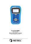
8
3
BACKLIT LCD DISPLAY UNIT
4
OPTICAL SERIAL COMMUNICATION INTERFACE
5
SAFETY INPUT TERMINALS , dia. 4mm, marked L, N, PE and P (terminal used for earth measurements
in a live condition).
maximum voltage with respect to earth = 550 V
6
MARKED SOCKET
FOR THE CONNECTION OF A CURRENT CLAMP
3. GENERAL USE
The measurements are made directly (voltage, frequency, and current if a clamp is connected) or by pressing
the TEST key.
Voltage and/or frequency measurements are accessible in all "active" settings of the switch.
3.1
AUTOMATIC CHECKS
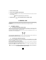
3.1.1
POSITION OF PHASE (MAINS SOCKET) CHECK
Upon connection, the instrument measures the voltages between conductors "L" and "N" (ULN), between
conductors "L" and "PE"(ULPE), between conductors "N" and "PE" ‘(UNPE), and between the voltage probe - if
a rod is connected to the terminal P - and conductor "PE".
The conductor that has the highest potential is taken to be the phase, designated by the letter "L" and
identified by one of the following displays :
Or
The measuring cable supplied with the instrument bears a white mark making it possible to determine the
position of the phase on the mains socket.
The instrument also determines the frequency for any frequency ≥ 15.3Hz or DC
3.1.2
THE PROTECTIVE CONDUCTOR (PE) CHECK
In a loop measurement (ZLOOP) or an earth measurement in a live condition (REARTH), when the TEST
key is pressed, the instrument first measures the potential difference UC between the local earth (user's
potential, via the TEST key) and the "PE" terminal.
If UC > UL, where UL is the limit contact voltage (UL = 25 or 50 V : see § 3.2 : SET-UP), the instrument
indicates that it is impossible to make a measurement.
If a measurement is triggered, the instrument then monitors voltage UNPE : if it increases by more than 20 V,
the instrument stops the measurement and reports an error.
Pressing the TEST key again causes a return to voltage measurement mode.
In a loop measurement with 2 wires (ZLINE position), measurement of the potential between
the earth and the "PE" conductor is omitted
9
3.1.3 MEASUREMENT CONDITIONS CHECK
or a measurement to be authorized, in addition to the above two checks (determination of the position of the
phase and of the voltage of the PE conductor), the following conditions must be satisfied:
- ULN, ULPE and UNPE < 550 V,
- voltage: f < 450Hz; current: 20Hz < f < 450Hz,
- loop or earth measurements in live condition: f = 15,3 to 65Hz,
- correct connection of the measuring cables (terminals connected and not interchanged).
Toute interdiction de mesure est accompagnée d'un message d'erreur (voir § 7), d'un bip d'erreur et
de l'affichage clignotant du symbole .
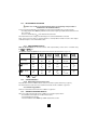
3.2
INSTRUMENT CONFIGURATION (SET-UP)
=> Set the rotary switch to the SET-UP position.
The parameter or value configured is validated upon return to the "PUSH btn" screen.
Warning: if the switch is turned before the return to the "PUSH btn" screen, the modified data are
lost.
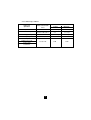
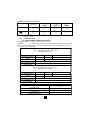
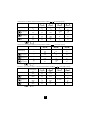
The table below indicates the various parameters that can be configured and their programming sequence.
Remark: generally, changes from "ON" to "OFF" and/or changes of the values of the parameters are effected
using the
key.
Parameter
Presses
Default
values
Values
Euro (JJ/MM)
US (MM/JJ)
AAAA
HH:MM
bAtt
User
adjustable
Time / Date
2
Type of power supply
2nd +
Activate/deactivate automatic
shutdown
2nd + 2x
on
OFF
on
Automatic shutdown time
2nd + 3x
01 to 59 mm
5mn
Activate/deactivate the buzzer
2nd +
on
OFF
on
nd
Display the internal parameters of
the instrument
Number of measurements in
"SMOOTH" mode
Printing of configuration
Printer configuration
(data rate)
Default configuration
+ MEM successive
niMH
successive
2nd + TEST
bAtt
serial no.
software version
date of calibration
LCD screen
2 to 5
3
300 to 9600 bauds
9600
PRINT
2nd +
PRINT
TEST + TEST
10
see §3.2.1
Parameter
Presses
Erase memory (totally or partially)
Reference voltage for the
calculation of Ik
Value of the low current ITEST
in "non-tripping" measurement
Threshold voltag UL
Default
values
Values
see §3.6
MEM
MORE
x2
see § 4.3.2
voltage
measured
MORE
x3
6,9 or 12 mA
see § 4.2.2
12 mA
MORE
x4
25 or 50 V
50 V
Alarms :
Earth resistance threshold
2nd
+
MORE
Loop resistance or impedance
threshold
2nd
+
MORE
x2
see § 4.4.2
Measured current threshold
2nd
+
MORE
x3
see § 4.6.2
see § 4.2.2
3.2.1 RESTORING THE DEFAULT CONFIGURATION
This can be used to restore the delivery configuration.
In SET- UP position:
PUSH
btn
TEST
dFLt
TEST
for validation and programming
of the default configuration
PUSH
btn
3.3
COMPENSATION OF THE LEADS
The leads must be compensated for measurements of low loop and earth resistance values, in order to make
the measurements more accurate.
If a compensation already exists, the
symbol is displayed. To view the compensation values, use the
4keys.
MORE and
11
3.3.1 APPLYING A COMPENSATION
Set the switch to one the LOOP/RCD positions.
Connect one end of the three-conductor cord terminated by 3 leads to the device. Short-circuit the 3 leads.
In the case of a mains outlet, connect the two earth pins with the earth pins with leads.
Perform a long press on the TEST button.
During the measurement, the device displays "LEAd" and the
symbol, and the dashes blink.
At the end of the measurement, the 4 key is used to view the values of R∆L, R∆N and R∆PE.
3.3.2 WITHDRAW A COMPENSATION
Set the switch to one of the LOOP/RCD positions.
Connect nothing to the terminals, or leave the leads open.
Then perform a long press on the TEST button.
During the measurement, the device displays "LEAd" and the
symbol and the dashes blink.
To exit from compensation of the leads, perform a second long press on the TEST key.
symbol is lit steadily.
If the compensation of the leads is effective, the
If the compensation has not been performed, the symbol is not displayed and the compensation values are zero.
At the end of the measurement, the device reports that the result found is greater than 5 Ω and withdraws the
compensation of the leads.
For exit from compensation of the leads, perform a second long press on the TEST key.
3.3.3
POSSIBLE ERROR MESSAGES
Display - Indication
Hz
Uxy > 2V
Ω
> 5Ω
Remark - Possible cause
The voltage on the terminals exceeds 2 V.
Check your connections.
The measured resistance of the leads is greater than 5 Ω.
If this is not intentional, to withdraw the compensation,
check your connections.
12
3.4
RECORDING MEASUREMENT RESULTS (MEM)
IMPORTANT - Each measurement stored in the instrument is identified by 2 indices: an OBJ no. and a
TEST no.; a given object (OBJ) generally contains several TEST nos.
For example: an OBJ no. can be used to locate an installation, and the TEST nos. identify the various
measurements made on this installation.
At any time, the user can store the result of a measurement and all of the parameters associated with the
measurement: date, time, type of measurement, measurement parameters, etc.
The location proposed by default is the first free memory location.
measurement
to be stored
MEM
03 06
OBJ TEST
FrEE (1)
selection of storage address using the following keys :
and
mesure
storage at the
selected address (2)
mémorisée
1)
"FrEE": the selected memory location is free / "OCC": the selected memory location is occupied
(2)
whether the location selected is occupied or not (previously recorded values are overwritten)
Note : Up to 100 measurements can be stored (e.g. 10 objects each having 10 tests, or any other combination).
3.5
RECALLING RECORDED VALUES (MR)
2nd + MEM
MR
The group of measurements (OBJ) and the measurement (TEST) to be retrieved on the display unit are
selected using the
and
keys.
13
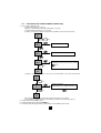
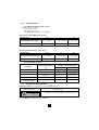
3.6
ERASING RECORDED VALUES
The memory of the instrument can be erased, totally or partially, in the SET-UP rotary switch position:
Complete
erasure of the
memory
Erasure of a memory block
(OBJ)
Erasure of a memory line
(TEST)
PUSH
PUSH
PUSH
btn
btn
btn
MEM
MEM
MEM
CLr
CLr
CLr
ALL
ALL
ALL
MEM
MEM
MEM
X2
MEM
FrEE
ALL
02 07
02 07
OBJ TEST
OBJ TEST
MEM
MEM
PUSH
btn
OCC
OCC
MEM
Select the
memory
block (OBJ)
to erase
MEM
MEM
02 07
02 07
OBJ TEST
OBJ TEST
FrEE
FrEE
MEM
MEM
PUSH
PUSH
btn
btn
14
Select the
memory
line TEST
to erase
3.7
PRINT
PRINTING MEASUREMENT RESULTS (PRINT)
: print the measurement made and all of the parameters attached to it.
Examples of printing tickets:
Remark : In the SET-UP position, pressing the PRINT key triggers printing of the configuration of the instrument.
3.8
PRINTING RECORDED VALUES (PRINT MEM)
Recorded values can be printed with the switch in any position except SET-UP or OFF.
PRINT MEM
2nd +
PRINT
01 01 : 1st memory location used
to select the values to be printed
06 05 : last memory location used
PRINT
Printing of all measurements
between he 1st and last
memory location selected
15
4. MEASUREMENTS
4.1
VOLTAGE MEASUREMENT
4.1.1 DESCRIPTION OF THE FUNCTION
Voltage measurement is accessible with the switch in any position except SET-UP or OFF.
4.1.2
PREPARATION OF THE MEASUREMENT (CONNECTION)
=> Switch the instrument on
=> Connect the instrument to the installation using
the measuring cable terminated by a mains plug,
or
=> Use the separate cables to make the connection.
4.1.3
MEASUREMENT PROCEDURE
Once connected, the instrument indicates any voltage(s) present on its terminals.
Do not use the instrument on an electrical installation exceeding 550 V with respect to earth
4.1.4 MEASUREMENT RESULTS
The measured values and complementary results can be consulted directly using
the
and MORE Keys, whatever the setting of the switch.
Parameters accessible in the 3P:
Initial display
Initial display
Pressing the
MORE
or
MORE
MORE
(1st press)
(2nd press)
R∆E
Hz
RE ALARM
UHE
-------
UL
Hz
RE ALARM
R∆E
USE
-------
UL
key once more returns to the initial display.
Parameters accessible in the 2P:
Initial display
Initial display
Pressing the
MORE
MORE
MORE
(1st press)
(2nd press)
Hz
RE ALARM
UHE
R∆E
-------
UL
key once more causes a return to the initial display.
16
Parameters accessible in the REarth setting:
Initial display
Initial display
(1 press)
st
(2nd press)
(3nd press)
Pressing the
or
MORE
MORE
MORE
(1st press)
(2nd press)
R∆ L
Hz
RA ALARM
ULN
----
UL
Hz
RA ALARM
R∆PE
ULPE
----
UL
Hz
RA ALARM
R∆ N
UNPE
----
UL
Hz
RA ALARM
----
UP
----
UL
key once more returns to the initial display.
Parameters accessible in the ZLoop setting:
MORE
MORE
(1st press)
(2nd press)
Hz
UREF
R∆ L
ULN
ZL ALARM
UL
Initial display
Initial dispaly
Hz
(1st press)
(2 nd press)
Pressing the
or
MORE
U
REF
R∆PE
ULPE
ZL ALARM
UL
Hz
UREF
R∆ N
UNPE
ZL ALARM
UL
key once more returns to the initial display.
Parameters accessible in the ZLine setting:
Initial display
Initial dispaly
(1st press)
(2 nd press)
Pressing the
or
MORE
MORE
MORE
(1st press)
(2nd press)
Hz
UREF
R∆ L
ULN
ZL ALARM
UL
R∆PE
Hz
UREF
ULPE
ZL ALARM
UL
Hz
UREF
R∆ N
UNPE
ZL ALARM
UL
key once more returns to the initial display.
17
Parameters accessible in the current measurement
Initial display
Initial dispaly
(1st press)
(2 nd press)
Pressing the
or
MORE
setting:
MORE
MORE
(1st press)
(2nd press)
Hz
Hz
----
I
ULN
IALARM
Hz
Hz
I
ULPE
---IALARM
Hz
Hz
I
UNPE
---IALARM
key once more returns to the initial display.
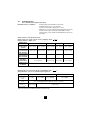
4.1.5 CHARACTERISTICS
4.1.5.1 Measurement ranges and accuracy
the value displayed is guaranteed only for a voltage ≥ 10 VRMS (all settings of the switch
Frequency :
except
) or, in the
, position, for a current ≥ 100 mARMS
Display range
Voltage
400 V
4000 V
measurements
Specified
measurement domain
2.0 - 79.9 V
80.0 - 399.9 V
Measurements of
Accuracy
± 4% ± 5 pt
± 2% ± 1 pt
the potential of
Input impedance
the voltage probe
Contact
voltage
measurement
Operating
frequency
Specified
measurement
domain
Accuracy
DC and 15,3 à 450 Hz
2.0 – 100.0 V
± 15% ± 2 pt
measurement
Specified
measurement domain
Resolution
Accuracy
(45Hz < freq. < 65Hz)
4.5 MΩ in series with 4.7 nF
Input impedance
Display range
± 2% ± 1 pt
440 kΩ
Operating
frequency
Frequency
400 - 550 V (DC or RMS)
15,3 to 65 Hz
400 Hz
4000 Hz
15.3 – 399.9 Hz
400 – 450 Hz
0.1 Hz
1 Hz
± 0,1% ± 1pt
18
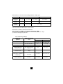
4.1.5.2 Influencing conditions
Variation of the measurement
Influencing
quanstities
Limits of the domain
Temperature
-10 à + 55 °C
1 %/10 °C ± 1pt
Relative humidity
10 to 85 % HR at 45°C
2%
POwer supply voltage
6,8 to 10 V
Frequency
15,3 to 450Hz
0,5%
1%
0 to 500 V DC
50dB
40dB
of use
Typical
1 % / V + 1pt
Maximum
2 %/10 °C + 2pt
3 % + 2 pt
2%/ V + 2pt
Series mode rejection in AC
50/60Hz series mode
rejection in DC
Common mode rejection in
50/60Hz AC
19
4.1.6
WARNINGS OR ERROR REPORTS
Preliminary remark: The complete list of coded errors is given in § 7.
Display - Indication
Hz
> 550V
Remark - Possible cause(s)
One of the voltages measured (ULN, ULPE, or UNPE)
is > 550V.
<15.3Hz (or) >65Hz
or 450Hz
ULN (or) UNPE (or) ULPE
Hz
ULN
Er08
n PE
HZ
UNPE > 25 (or) 50V
Er02
L
Frequency outside measurement domain
(depends on type of measurement)
N and PE reversed
N not connected
N not connected and L and PE reversed
In ZLINE position :
Permutation, PE-L-N instead of L-N-PE
L and PE reversed
Permutation, N-PE-L instead of L-N-PE
In ZLINE position :
L and PE reversed
Permutation, N-PE-L instead of L-N-PE
L
L not connected
L not connected and N and PE reversed
Hz
UNPE > UL (threshold voltage)
Er03
UNPE > 25 (or) 50V
Hz
UHE (or) USE> 30V
Hz
UC > 25 (or) 50V
In 2P or 3P position:
One of the voltages is > maximum allowed spurious voltage.
In ZLOOP or REARTH position :
Potential difference between the local earth and PE too high
Press the TEST key to exit from the error conditions.
20
.
4.2
2P AND 3P EARTH MEASUREMENT
4.2.1
DESCRIPTION OF THE FUNCTION
3P and 2P earth measurements are made in a power-off condition.
The measurements are made with two auxiliary rods (3 poles) and one auxiliary rod (2 poles), respectively.
Note however that measurements with 2 auxiliary rods are more accurate.
Measurement in 3P mode: the instrument generates an alternating current square wave (128 Hz) between
terminals H and E, then measures the voltage between terminals S and E: from this voltage and the current
generated, it deduces global earthing resistance RE.
Measurement in 2P mode: the instrument generates a signal between terminals H and E, measures the
voltage on terminal H, and deduces resistance RE.
4.2.2 PREPARATION FOR THE MEASUREMENT (CONNECTION)
=> In SET-UP, set the value of the no-load voltage generated by the instrument: UL = 50 V, or 25V
in a damp environment (see § 3.2).
=> If necessary,
■
adjust the alarm, RE ALARM , in the SET-UP mode,
PUSH
btn
2nd
MORE
>
direction of alarm (> or<)
88.88
location of decimal point
88.88
setting of the values of each of the 4 digits,
selected by successive presses on the
88.88
MORE
keys
x3
PUSH
btn
■
■
activate the alarm by pressing the ALARM key and 2nd key after SET-UP exit .
An overshoot of an alarm threshold during a measurement is indicated by a continuous
audible signal
compensate the measuring cables (see § 3.3).
21
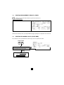
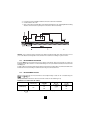
=> Cut off power to the installation and disconnect the earth of the installation
=> Set the switch to 2P or 3P.
=> Then connect the measuring cables to the instrument and to the rods, complying with the following
distances and connections (example of connection for 3P measurement).
Remark : to be sure that rod S is located in a zone that is not influenced by other earth electrodes, move it
( 10% of the distance and repeat the measurement. The result must not change or just from few %.
4.2.3
MEASUREMENT PROCEDURE
Press the TEST key. The instrument measures voltages UHE and USE. If the measurement is possible, the
instrument checks the resistances of rods S and H: if they are correct, the instrument makes the measurement
and displays it.
To make a 2P measurement, plant a single rod and connect the measuring cables to terminals H and E of the
instrument. The measurement proceeds in the same way as a 3P measurement.
4.2.4
MEASUREMENT RESULTS
After the measurement, the measured values and complementary results can be consulted using the
and MORE keys.
(The quantities accessible before the measurement is made are described in § 4.1.4)
Parameters accessible in the 2P setting :
Initial display
Initial display
Pressing the
MORE
RH
RE
MORE
MORE
MORE
(1st press)
(2nd press)
(3nd press)
Hz
RE ALARM
-------
R∆E
UHE
key once more causes a return to the initial display.
22
UL
Parameters accessible in the 3P setting :
MORE
Initial display
MORE
MORE
(1st press)
(2nd press)
(3nd press)
Hz
RE ALARM
R∆E
RH
Initial display
RE
UHE
RS
Hz
RE
Pressing the
4.2.5
or
-------
UL
RE ALARM
R∆E
-------
UL
USE
key once more causes a return to the initial display.
MORE
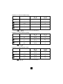
CHARACTERISTICS
4.2.5.1 MEASUREMENT RANGES AND ACCURACY
Particular reference
conditions
: resistance of auxiliary earths < 100 Ω
: resistance of the cable connected to terminal E of the instrument compensated
The instrument automatically selects one of two ,measurement currents according to the sum of Re and
Rh as well as the set voltage limit.
RH + RE ≥ 9 kΩ at 50V or RH + RE ≥ 4.5kΩ at 25V
Measuring current = 5mA
Display range
40Ω
400 Ω
4000 Ω
Specified measurement
domain
0.50 – 39.99 Ω
40.0 – 399.9 Ω
400 – 3999 Ω
Accuracy
± 2% ± 5pt
± 2% ± 2pt
Measuring current
5 mA
Max. acceptable resistance
in the current loop
8 kΩ (50 V) or 4 kΩ (25 V)
RH + RE ≥ 9 k? at 50 V or RH + RE ≥ 4,5 k? at 25 V
Measuring current = 500 µA
Display range
400 Ω
4000 Ω
40.00 kΩ
Specified measurement
domain
0.5 – 399.9 Ω
400 – 3999 Ω
4.00 – 39.99 kΩ
Accuracy
± 2% ± 5pt
± 2% ± 2 pt
Measuring current
500 µA
Max. acceptable resistance
in the current loop
45 kΩ
Common characteristics
Maximum acceptable resistance
in the voltage loop
50 kΩ
Frequency
128 Hz
No-load voltage
25 V or 50 V
Accuracy of rod
resistance measurements
5% + 5pt
23
4.2.5.2 Influencing conditions
Influencing quantities
Limits of the domain
of use
Variation of the measurement
Typical
Maximum
Temperature
-10 to + 55 °C
1%/10 °C ± 1pt
2%/10 °C + 2pt
Relative humidity
10 to 85% RH at 45°C
2%
3% + 2 pt
Power supply voltage
6.8 to 10 V
1% / V ± 1pt
2%/ V + 2pt
Voltage in series in the
voltage measurement
loop (S-E)
0 to 30 V
from 15.3 to 450Hz
Except at 128 ± 16Hz
0.2%/V + 1 pt
0 to 30 V
from 15.3 to 450Hz
Except at 128 Hz
0.2%/V + 1 pt
0 to 50kΩ
0.5%/10kΩ
+ 0,015% RH
1%/10kΩ
+ 0,015% RH
0 to 50kΩ
0.5%/10kΩ
+ 0,015% RS
1%/10kΩ
+ 0,015% RS
Voltage in series in the
current injection loop
(H-E)
Current loop rod
resistance (RH)
Voltage loop rod
resistance (RS)
4.2.6
WARNINGS OR ERROR REPORTS (2P OR 3P EARTH MEASUREMENTS)
Preliminary remark : he complete list of coded errors is given in § 7
Display - Indication
Hz (or)
UHE OU USE > 30V
Er22
COMP
Remark - Possible cause
UHE or USE is > 30V : the measurement is affected.
Try to move rods H and S
- resistance on rods H or S too high,
- or earth resistance too high,
- or spurious voltages too high.
Check the connections and the auxiliary rods.
Press the TEST key to exit from the error conditions.
If the value of RE is negative, it means that:
- the rod resistances are too high,
- or the spurious voltages are too high,
- or the compensation of the cables is wrong. It must be done over with the cables actually used
(see § 3.3).
24
4.3
EARTH MEASUREMENT IN LIVE CONDITION (REARTH)
4.3.1 DESCRIPTION OF THE FUNCTION
■
■
This measurement is made with a single auxiliary rod (voltage probe) connected to terminal (P),
yielding a saving of time with respect to a conventional measurement with 2 auxiliary rods.
A specific additional current clamp is necessary to make a selective earth measurement.
he instrument automatically detects the connection of the voltage and current probes.
When the TEST key is pressed, the instrument:
- checks that the amplitude and frequency of the voltages present are correct,
- checks the resistance of the auxiliary rod,
- interchanges L and N internally if the 2 conductors are reversed in the socket,
- measures the voltage between the TEST key and terminal PE,
If these quantities are correct, the instrument generates, according to the user's selection, a high current
("tripping" mode
) or a low current ("non-tripping" mode
on 30mA RCD or more) between
terminals L and PE and measures the voltage drop between terminals P and PE.
■
If the user selects measurement without tripping (
measures RA (global earth resistance).
), the current generated is low : the instrument
Note : if, during a earth measurement at low current, a earth fault breaker in the circuit still trips, measure the
leakage current with the current probe using the "current measurement" function of the instrument, then
change the measuring current ITEST (see § 4.2.2) with allowance for this leakage current. Otherwise, shortcircuit the circuit-breaker concerned and make the next measurement at high current for greater accuracy.
■
If the user has selected measurement with tripping (or if they have connected the current probe to make
a selective measurement), the current generated is high (
): arrangements may have to be made
to prevent the earth fault breaker from tripping (e.g. temporary shunting of the breaker). The instrumen
measures ZA (the global earthing impedance), RA and LA (the resistive and inductive parts of ZA).
Remarks:
- If the user selects measurement without tripping (
) and connects a current probe, the instrument
reverts to measurement with tripping and reports the change.
- If the user connects the current probe, it is the current measured by this probe that is used to calculate
RA. The lower this current, the more unstable the measurement is likely to be: in this case, smooth the
measurement using the "SMOOTH" function.
4.3.2
PREPARATION FOR THE MEASUREMENT (CONNECTION)
The instrument must be connected to the network in a live condition and the earth electrode
to be measured must not be disconnected.
=> If necessary, set, in the SET-UP mode :
■
UL (see § 3.2),
25
■
the current generated for the measurement at low current :
PUSH
btn
MORE
x5
I∆n 12 mA
Selection of current
MORE
twice to exit from programming
PUSH
btn
■
■
■
The type of compensation of the measuring cables (see § 3.3)
the alarm threshold ZA or RA :
the number of measurements to be counted to smooth the measurement (see § 3.2).
=> Set the switch to the REARTH position,
=> Activate the alarm by pressing the ALARM key,
=> Select the measuring current: press 2nd
+
5
=> high (
) for a greater accuracy:
- if there is no tripping of a earth fault breaker (measurement made upstream of the RCDs),
- if the earth fault breaker concerned is short-circuited for greater accuracy,
- in the case of a selective measurement using a current probe.
=> low (
) for a quick check :
=> Make the connections as indicated below, according to the type of installation to be checked.
=> Compensate the measuring cables (see § 3.3),
Case of an installation with a TT type neutral situation :
=> Connect the mains socket (or the
3 separate cables) to the installation
to be tested,
=> Plant the auxiliary rod at a distance
> 25 m from the earth electrode.
26
Case of an installation with a TN type neutral situation (selective measurement) :
=> Connect the mains socket (or the
3 separate cables) to the installation
to be tested,
=> Connect a current probe to the terminal
and encircle the earth of which the
resistance is to be measured: the current
used to calculate ZA SEL is that measured
by the probe,
=> Plant the auxiliary rod PE as close as
possible to the earth electrode to be
measured for a measurement that is as
accurate as possible,
=> Compensate the cables.
Note : without the current probe, what is measured is the global earth of the network, which is not very
significant.
Connecting the clamp configures the instrument in the tripping mode (power-level current).
Case of an installation with an IT type neutral situation (not isolated) :
Preliminary remarks :
- the power supply transformer of the installation must not be completely isolated, but earthed through an
impedance,
- the installation must also not be in first fault: start by checking the indication of the Permanent
Insulation Tester concerned,
- the "grounds to earth" RA and the earth of the power supply transformer must be separate to allow the
circulation of the measuring current.
=> Connect the mains socket (or the
3 separate cables) to the installation to
be tested,
=> Plant the auxiliary rod at a distance
> 25 m from the earth electrode.
4.3.3 MEASUREMENT PROCEDURE
The instrument first checks the resistance of the rod and measures the voltage between PE and earth, then
measures the voltages ULN, ULPE, UNPE.
If these values are correct, pressing the TEST key starts the measurement.
Remark : to be sure that the auxiliary rod is located in a zone not influence by other earth electrodes, move
the rod ( 10% of the distance and repeat the measurement. The result must not change. If it does, move the
rod until the earth measurement remains unchanged.
4.3.4 MEASUREMENT RESULTS
After the measurement, the measured values and complementary results can be consulted using the
and MORE keys.
(The quantities accessible before the measurement is made are described above, in § 4.1.4)
27
Parameters accessible in earth measurement in live condition,
Initial display
Initial display
(1st press)
(2 press)
nd
(3 press)
nd
Pressing the
MORE
MORE
MORE
MORE
(1st press)
(2nd press)
(3nd press)
(4nd press)
RA
LA
Hz
RA ALARM
R∆ L
ZA
ZA
ULN
UF
UL
RA
LA
Hz
RA ALARM
R∆PE
ZA
ZA
ULPE
UF
UL
RA
LA
Hz
RA ALARM
R∆ N
ZA
ZA
UNPE
UF
UL
RA
LA
Hz
RA ALARM
RP
ZA
or
MORE
ZA
UP
UF
key once more causes a return to the initial display.
Parameters accessible in earth measurement in live condition,
Initial display
MORE
RA
----
(1st press)
Hz
ULN
RA
Hz
----
ULPE
Initial display
(1st press)
(2nd press)
(3nd press)
Pressing the
or
mode (high current):
MORE
mode (low current):
MORE
(3nd press)
R∆ L
UF
RA ALARM
UF
RA ALARM
R∆PE
UL
Hz
----
UF
UL
RA
UNPE
Hz
RA AARM
RP
----
UP
UF
UL
(3nd press)
Pressing the
or
MORE
R∆N
key once more causes a return to the initial display.
RA
ZA SEL
RA
ZA SEL
RA
ZA SEL
RA
ZA SEL
(2nd press)
UL
RA
Initial display
(1st press)
MORE
(2nd press)
RA ALARM
Parameters accessible in selective earth measurement in live condition,
Initial display
UL
mode (high current):
MORE
MORE
MORE
MORE
(1st press)
---ISEL
---ISEL
---ISEL
---ISEL
(2nd press)
Hz
ULN
Hz
ULPE
Hz
UNPE
Hz
UP
(3nd press)
(4nd press)
R∆ L
UL
R∆PE
UL
R∆N
UL
RP
UL
RA ALARM
RA ALARM
RA ALARM
RA ALARM
key once more causes a return to the initial display.
28
4.3.5
CHARACTERISTICS
4.3.5.1 Measurement ranges and accuracy
Particular reference conditions :
nominal voltage of the installation = 90 to 550 V,
nominal frequency of use = 15.3 to 65 Hz,
resistance in series with voltage probe: < 100 Ω
inductive part < 0.1 x the resistive part of the impedance measured,
resistance of the cable connected to terminal PE corrected,
contact voltage < 5 V (potential of terminal PE with respect to the
local earth).
Characteristics of the measurements:
Characteristics in "high current" mode ("tripping" mode
Charge duration : 300µs cycle
Display range
Specified
measurement
domain
Peak measuring
current between
90V and 280V
Peak measuring
current between
280V and 550V
):
40 Ω
0.20 - 1.99 Ω
400 Ω
20.00 - 39.99 Ω 40.0 - 399.9 Ω
400 - 3999 Ω
1.06 to 3.25 Ω 0.90 to 3.25 A
0.79 to 2.83 A
0.24 to 2.47 A
0.03 to 0.76 A
1.27 to 2.73 A
1.13 to 2.57 A
0.55 to 2.42 A
0.08 to 1.18 A
Accuracy of the
impedance
measurement
2.00 - 19.99 Ω
4000 Ω
1.20 to 2.71 A
± 10 % ±15 pt
± 5 % ±15 pt
Additional error
for Rearth
± 5 % ±5 pt
± 5 % ±2 pt
± 0,3 Ω
Max. inductance acceptable for the measurement : 20 mH (display range 400.0 mH)
Characteristics in "low current" mode ("non-tripping" mode
Charge duration : cycle of one network frequency period.
Display range
Specified
measurement
domain
RMS measuring
current
Accuracy of the
resistance
measurement (2)
(2)
):
400Ω
0,5 - 1,9Ω
4000Ω
2,0 - 19,9Ω
20,0 - 399,9Ω
400 - 3999Ω
6 - 9 - 12 mA (adjustable in «SET-UP» mode : see & 3.2)
± 15% ± 10 pt
± 15% ± 5 pt
No measurement of the inductive part in"low current" mode.
29
Characteristic in "selective" mode: Charge duration : 300 µs cycle
Display range
400 Ω
Specified
measurement
domain
0.5 - 1.9 Ω
Peak measuring
current (3)
≥ 30 mA
Accuracy of the
resistance
measurement (4)
(3)
(4)
± 15 % ± 5 pt
4000 Ω
2.0 - 19.9 Ω
20.0 - 399.9 Ω
400 - 3999 Ω
≥ 5 mA
≥ 2 mA
≥ 10 mA
± 10 % ± 5 pt
± 15 % ± 5 pt
The measuring current is that measured by the current probe.
No measurement of the inductive part in "selective" mode.
Characteristics common to all measurement modes:
Ω
- Max. resistance acceptable in series with the voltage probe: 15 kΩ
- Accuracy of measurement of the resistance in series with the probe: 20 % + 10 pt
(resolution 0,1 kΩ; display range 400.0 kΩ
4.3.5.2 Influencing conditions
Influencing
quantities
Limits of the domain
of use
Temperature
-10 à + 55 °C
Relative humidity
10 to 85 % HR at 45 °C
2%
Power supply voltage
6.8 to 10 V
1 % / V + 1pt
2 %/ V + 2 pt
Network voltage of the
installation tested
99 to 101 % of nominal
frequency
0.5%
1 % + 1 pt
Network voltage of the
installation tested
85 to 110 % of nominal
voltage
0.5%
1 % + 1 pt
Resistance in series qith the
voltage probe ( earth in live
condition only)
0 to 15 kΩ
0.1%/kΩ
Contact voltage (Uc)
0 to 50 V
0.1%/10V
30
Variation of the measurement
Typical
1 %/10 °C ± 1 pt
Maximum
2 %/10 °C + 2 pt
3 % + 2 pt
0.2 %/ kΩ + 1 pt
0.2 %/10 V
4.3.6
WARNINGS OR ERROR REPORTS (EARTH MEASUREMENT IN LIVE CONDITION)
Preliminary remark: The complete list of coded errors is given in § 7.
Affichage - Indication
Hz
UC > 25 (ou) 50V
Hz
<90 V
Hz
UNPE> 25 (ou) 50V
< 15.3 Hz (ou) > 65Hz
ULN (ou) UNPE (ou) ULPE
Commentaire - Cause possible
Voltage > ULbetween the TEST key and PE: the measurement
is disabled.
One of the voltages, ULN or ULPE is < 90 V : the measurement
is impossible.
UNPE is AC and > UL : the measurement is impossible.
The frequency of ULN, ULPE, or UNPE is < 15,3 Hz or >
65 Hz : the measurement is impossible.
NO
rOd
Er10
UP > 50V (ou) 25V
Ω
RP > 15kΩ
UP
The rod is not connected, the measurement is stopped.
UP > UL : the measurement is disabled.
Resistance of the auxiliary rod too high: the measurement
is stopped.
Connection of a current probe after selection of measurement
without tripping: the instrument automatically reverts to
measurement with tripping and reports the fact.
Er04
UF > 50V (ou) 25V
During the measurement, UF exceeds the value set in the
SET-UP mode: the measurement is stopped.
Er05
During a selective measurement, the product of the current
measured by the current probe and the measured voltage is
too low: the measurement is stopped.
Er06
During a selective measurement, the current measured by the
current probe is too unstable: the measurement is stopped.
I = ----
The temperature of the instrument is too high: the masurement
is stopped. Pressing the TEST key has no effect until the
temperature of the instrument is again below 60°C; another
HOt
measurement can then be started.
Press the TEST key to exit from the error conditions.
> 80°C
31
4.4
WIRE LOOP MEASUREMENT (Z LOOP)
4.4.1 DESCRIPTION OF THE FUNCTION
In a TT network, measurement of loop impedance LPE is a rapid and practical way of checking a earth
resistance without planting auxiliary rods. In this case, the measurement includes the earthing resistance
of the power supply transformer of the installation and the resistance of the distribution cables. It is therefore
a high earth measurement, and any error is on the safe side.
In TT and TN networks, this function can also be used to check and size the protective systems in place by
a rapid and easy measurement of the loop impedances between L and PE, L and N, and N and PE. This
function can also be used to calculate the corresponding short-circuit currents (sizing of fuses and circuit
breakers).
Note that the instrument allows measurement of loop impedance LPE behind 30mA circuit-breakers without
causing them to trip (principle patented by Chauvin Arnoux).
In an IT network, use the instrument's "ZLINE" function.
The measurement principle is the same as for an earth measurement in a live condition.
When the TEST key is pressed, the instrument :
- checks that the amplitude and frequency of the voltages present are correct,
- measures the voltage between the TEST key and terminal PE,
- interchanges L and N internally if the 2 conductors are reversed in the socket,
- generates a current (high or low according to the user's selection) between terminals L and PE,
- measures loop impedances ZLN, ZLPE, et ZNPE.
Note: the measurement of ZLN does not trip the earth fault breakers even with high currents.
32
4.4.2 PREPARATION FOR THE MEASUREMENT (CONNECTION))
=> If necessary, in SET-UP mode:
- set threshold voltage UL (see § 3.2),
- the type of compensation of the measuring cables (see § 3.3))
- set the alarm threshold ZL or R L (see § 4.2.2)
- possibly, select a value of UREF to be used for the calculation of the short-circuit current :
PUSH
btn
2nd + MORE x2
>
direction of alarm (> or<)
88.88
location of decimal point
88.88
setting of the values of each of the 4 digits,
selected by successive presses on the
88.88
MORE
keys
x3
PUSH
btn
- possibly, select a value of UREF to be used for the calculation of the short-circuit current:
PUSH
btn
MORE
x4
selection of voltage :
Uref MEAS
Ik
MORE
MEAS/230/400/127 ou MEAS/220/380/110
x3
PUSH
btn
- the current generated for the measurement in low current mode (see § 4.2.2),
- set the number of measurements to be counted to smooth the measurement (see § 3.2)
=> Set the switch to the ZLOOP position,
=> Activate the alarm by pressing the ALARM key,
=> Connect the line power plug or the 3 separate cables to the installation to be tested,
33
=> Compensate the measuring cables (see § 3.3),
=> Select the measuring current: press 2nd + 5
=> high (
) for a greater accuracy:
- if no tripping of a earth fault breaker is foreseen (measurement made upstream of the RCDs),
- if the earth fault breaker concerned is short-circuited for greater accuracy,
=> low (
) otherwise for a rapid check
The connection diagrams are the same as for earth measurements in a live condition, but without the voltage
or current probe (see § 4.2.2).
4.4.3 MEASUREMENT PROCEDURE
The instrument first checks the resistance of the rod and measures the voltage between PE and earth, then
measures voltages ULN, ULPE, UNPE.
If these values are correct, pressing the TEST key starts the measurement: as soon as the result is available,
it is displayed.
Note: for measurements on three-phase systems, the loop impedance must be measured between each
phase conductor, the neutral conductor, and the protective conductor.
4.4.4 MEASUREMENT RESULTS
After the measurement, the measured values and complementary results can be consulted using
the
and MORE keys.
(The quantities accessible before the measurement is made are described above, in § 4.1.4.)
Initial
display
Initial display
(1st press)
(2nd press)
Pressing the
or
MORE
MORE
MORE
(1st press)
(2nd press)
RLPE
LLPE
UREF
Hz
ZLPE
ZLPE
IKLPE
ULPE
RLN
(3nd press)
LLN
UREF
Hz
ZLN
ZLN
IKLN
ULN
RNPE
LNPE
UREF
Hz
ZNPE
ZNPE
IKNPE
UNPE
MORE
MORE
MORE
(4nd press)
(5nd press)
----
R∆PE
ZL
ALARM
---ZL
ALARM
---ZL
ALARM
UL
R∆ L
UL
R∆ N
UL
key once more causes a return to the initial display.
Note : In non-trip mode the inductive component is not measurable due to the weak test current. The values
LLPE, LNPE, ZNPE, are not displayed (display shows - - - -). The value LLPE is displayed in the LLN field.
4.4.5 CHARACTERISTICS
4.4.5.1 Measurement ranges and accuracy
Particular reference conditions :
- nominal voltage of the installation = 90 to 550V,
- nominal frequency of use = 15.3 to 65Hz,
- inductive part < 0.1 x the resistive part of the impedance measured.
The characteristics of loop measurements with 3 wires, with (
) or without tripping (
) are the
same as those of earth measurements in a live condition, with or without tripping, respectively: see § 4.3.5.1.
34
Characteristics of calculation of short-circuit current Ik :
Display range
Resolution
Accuracy
400 A
4000 A
0,1 A
40 kA
1A
10 A
Resistances, impedances :
Accuracy values indicated for earth measurements in a live condition (see § 4.2.5)
Short-circuit current :
Accuracy of impedances + accuracy of measuremnt of voltage Umes, if it is used
Calculation formula
IK = UREF / ZLOOP (ou ZLINE)
4.4.5.2 Influencing quantities
Same as for earth measurements in a live condition (cf. § 4.3.5.2)
4.4.6 WARNINGS OR ERROR REPORTS (ZLOOP LOOP MEASUREMENTS)
Preliminary remark : The complete list of coded errors is given in § 7.
Same as for earth measurements in a live condition, except for the rod and the current probe measurement,
which do not apply to loop measurements: see § 4.3.6.
4.5
WIRE LOOP MEASUREMENT (Z LINE)
4.5.1 DESCRIPTION OF THE FUNCTION
This function measures the line impedance between conductors "L" and "N" of the power network. This
measurement can also be used to calculate short-circuit currents, in order to size fuses and circuit breakers.
It is possible to check the impedance between conductors "L" and "PE" or between two "L" conductors, but
the measuring cables must systematically be connected to terminals "L" and "N" of the measuring instrument.
4.5.2 PRÉPARATION DE LA MESURE (BRANCHEMENT)
PREPARATION FOR THE MEASUREMENT (CONNECTION)
=> If necessary, in SET-UP mode :
- set the threshold voltage UL (see § 3.2),
- set the alarm threshold ZL ou RL (see § 4.4.2),
- choose the value of UREF to be used to calculate short-circuit currents (see § 4.4.2)
=> Set the switch to ZLINE,
=> Connect the line power plug (or 2 separate cables) to the installation to be tested.
=> Activate the alarm by pressing the ALARM key,
=> Compensate of the measuring cables (see § 3.3)
The connection diagrams are the same as for earth measurements in a live condition, but without the voltage
or current probe or the connection to terminal PE (if this connection is made, it is not taken into account) :
see § 4.3.2.
35
4.5.3
MEASUREMENT PROCEDURE
In the case of 2-wire loop measurements, there is no monitoring of the potential of
terminal PE nor the installation PE line.
Loop measurements with 2 wires are identical to loop measurements with 3 wires except as follows :
- the voltage between the TEST key and PE is not measured: only the potential between terminals L and
N is measured;
- there is no monitoring of UNPE hich enable the measurement..
The instrument measures voltage ULN and voltages ULPE, UNPE if terminal PE is connected.
Nota : pour les mesures dans les systèmes triphasés, cette impédance doit être mesurée entre chaque
conducteur de phase et le conducteur du neutre.
4.5.4
MEASUREMENT RESULTS
After the measurement, the measured values and complementary results can be consulted using
the
and
MORE
keys.
(The quantities accessible before the measurement is made are described above, in § 4.1.4.)
Initial
Initial display
(2nd press)
Pressing the
or
MORE
MORE
display
(1 press)
(2 press)
RLN
LLN
UREF
Hz
ZLN
ZLN
IKLN
ULN
LLN
RLN
(1st press)
MORE
st
nd
(3 press)
nd
UREF
Hz
ZLN
ZLN
IKLN
ULPE
RLN
LLN
UREF
Hz
ZLN
ZLN
IKLN
UNPE
MORE
MORE
(4 press)
nd
MORE
(5nd press)
---ZL
ALARM
---ZL
ALARM
---ZL
ALARM
key once more causes a return to the initial display.
4.5.5 CHARACTERISTICS
4.5.5.1 Measurement ranges and accuracy
The particular reference conditions are the same as for 3-wire loop measurements (see § 4.3.5).
The characteristics are the same as for earth measurements in a live condition: see § 4.2.5.1.
4.5.5.2 Influencing quantites
Same as for earth measurements in a live condition: see § 4.2.5.2.
4.5.6 WARNINGS OR ERROR REPORTS
Same as for earth measurements in a live condition (see § 4.2.6) except as follows:
- the rod and the current probe are not taken into account,
- error management on ULN only,
- measurement between the TEST key and PE not taken into account.
36
R∆
UL
R∆
UL
R∆
UL
4.6
CURRENT MEASUREMENT (
)
4.6.1 DESCRIPTION OF THE FUNCTION
In the
, position, the instrument measures the alternating current continuously, without the TEST key
being pressed.
The instrument deduces the current flowing in the cable(s) clamped by the probe according to the transformation
ratio of the probe.
4.6.2 PREPARATION OF THE MEASUREMENT (CONNECTION)
=> Connect the clamp to the measuring instrument (specific triple socket designed to avoid connection
errors)
=> Set the switch to
,
=> Clamp the cable of which the current is to be measured.
=> If necessary, in the SET-UP mode, set alarm threshold IALARM
PUSH
btn
2nd +
MORE
x3
>
direction of alarm (> or<)
88.88
location of decimal point
88.88
setting of the values of each of the 4 digits,
selected by successive presses on the
keys
88.88
PUSH
btn
=> If necessary, activate alarm threshold IALARM by pressing the ALARM key.
4.6.3 MEASUREMENT PROCEDURE
The measurement is started automatically and is continuous.
4.6.4 MEASUREMENT RESULTS
The measured values and complementary calculated results are described in the table of § 4.1.4
(position
of the switch).
37
4.6.5
CHARACTERISTICS
4.6.5.1 Measurement ranges and accuracy
Particular reference conditions :
- peak factor = 1.414,
- DC component < 0.1 %,
- operating frequency domain = 15.3 to 450 Hz.
Characteristics with an MN 20 current probe :
Display range
400 mA
Specified measurement domain
4A
5.0 - 399.9 mA
Accuracy
0.400 - 3.999 A
2 % + 10 pt
1.5 % + 2 pt
40 A
4.00 - 20.00 A
1.2 %+2 pt
Note : in measurement of ISEL, the accuracy is ancreassed by 5 %.
Characteristics with an C172 current probe :
Display range
400 mA
Specified measurement domain
Accuracy
4A
40 A
5.0 - 399.9 mA
0.400 - 3.999 A
4.00 - 20.00 A
2 % + 10 pt
1.5 % + 2 pt
1.2 %+2 pt
4.6.5.2 Influencing conditions
Influencing
Limits of the domain of
quantities
use
Typical
Température
-10 to + 55 °C
1 %/10 °C ± 1 pt
Relative humidity
10 à 85 % HR at 45 °C
Power supply voltage
6.8 to 10 V
Frequency (without the current probe)
15.3 to 450 Hz
0.5 %
1%
Common mode rejection in
AC 50/60Hz en DC
0 to 500 V AC
50 dB
40 dB
Variation of the measurement
2%
1 % / V + 1 pt
Maximum
2 %/10 °C + 2 pt
3 % + 2 pt
2 %/ V + 2 pt
4.6.6 WARNINGS OR ERROR REPORTS (
)
Preliminary remark: The complete list of coded errors is given in § 7.
Display - Indication
Er18
Prob
Remark - cause
The clamp is not connected: the measurement is impossi
Press the TEST key to exit from the error conditions.
38
5. GLOSSARY
Hz
I
IALARM
IKLN ; IKLPE ; IKNPE
ISEL
:
:
:
:
:
LE
LLN ; LLPE ; LNPE
R∆
R∆E
R∆ L
R∆N
R∆PE
RE
RA
RA SEL
RA ALARM
RE ALARM
RH
:
:
:
:
:
:
:
:
:
:
:
:
:
RL ALARM
RLN ; RLPE ; RNPE
RP
RS
:
:
:
:
UF
UHE
UL
:
:
:
ULN
ULPE
UNPE
UP
UREF
USE
ZE
ZLN ; ZLPE ; ZNPE
:
:
:
:
:
:
:
:
frequency of the signal
current
current threshold
short-circuit current between terminals L and N, L and PE, N and PE
current flowing in the current probe during a selective earth measurement in a
live condition.
inductive part of ZE
inductive part of impedance ZLN, ZLPE, ZNPE
global compensation between 2 terminals (2P and ZLine)
compensation of the cable in terminal E
compensation of the cable in terminal L
compensation of the cable in terminal N
compensation of the cable in terminal PE
global earthing resistance
earth resistance in earth measurement on live circuit
selective earth resistance
earth resistance alarm threshold
alarm threshold for earth resistance measurements
resistance of the auxiliary earth electrode (resistance of an additional earth
electrode, necessary for the measurements, through which the current flows :
standard NF EN 61557)
sloop resistance threshold
real part of impedance ZLN, ZLPE, ZNPE
resistance of the auxiliary rod in a earth measurement in a live condition
resistance of the auxiliary rod S (resistance of an additional earth electrode
used as a probe, used to tap the potential during the measurements :
standard NF EN 61557)
fault voltage as per standard NF EN 61557
voltage between terminals H and E
conventional limit contact voltage: 25 or 50 V, adjustable in the "SET-UP" mode
(see § 3.2)
voltage between terminals L and N
voltage between terminals L and PE
voltage between terminals N and PE
voltage between the voltage probe / auxiliary rod and PE
reference voltage for calculation of the short-circuit current
voltage between terminals S and E
global earthing impedance
impedance of the loop between L and N, between L and PE and between N and PE
ZL ALARM
:
loop impedance threshold
39
6. MAINTENANCE
6.1
REPLACING THE BATTERIES
The remaining battery charge level is indicated by the symbol
.
When the battery is flat (the symbol
flashes), the instrument emits an audible stop signal (5 beeps),
then automatically switches to standby. When the battery is low, display of the "BAtt" message indicates that
the measurement requested requires too much energy and cannot be made.
Note: when rechargeable batteries are used, this fact must be entered in the configuration of the instrument
("SET-UP" mode) to prevent incorrect operation of the instrument (risk of erroneous measurements or
malfunction of the instrument).
Check that none of the input terminals are connected and that the switch is set to OFF before
opening the instrument.
When the batteries are removed, there is enough reserve energy to preserve the date and time for one
minute. If this time is exceeded, the instrument, when next started up, prompts the user to check the date and
time by displaying the flashing message "tIME" for 2 seconds before displaying new measurements.
6.2
STORAGE
If the instrument is to be stored for more than 2 months, remove the batteries. It will then be necessary to
reset the instrument's time when it is next used.
6.3
CLEANING
Clean the housing of the instrument regularly. This can be done with a damp cloth or soapy water. Do not use
alcohol, solvents, or hydrocarbons.
6.4
METROLOGICAL VERIFICATION
Like all measuring or testing devices, the instrument must checked regulary.
This instrument should be checked at least once a year. For checking and calibration, contact one of our
accredited metrology laboratories (information and contact details available on request), at our Chauvin Arnoux
subsidiary or the branch in your country.
6.5
WARRANTY
Unless otherwise stated, our warranty is valid for 12 months following the date on which the equipment is
made available (extract from our General Conditions of Sale, available on request).
6.6
CUSTOMER SERVICE
For maintenance work, use only specified spare parts.
The manufacturer cannot be held liable for any accident that occurs following a repair done
other than by its Customer Service Department or an approved repairer.
Repair under and out of warranty :
Send the instrument to one of the MANUMESURE regional agencies, approved by Chauvin Arnoux
Information and coordinates on request: Tel.: 02 31 64 51 43 - Fax: 02 31 64 51 09
Repair outside mainland France :
For any repair (under or out of warranty), send the instrument back to the dealer.
6.7
REPAIR
For all repairs before or after expiry of warranty, please return the device to your distributor.
40
7. LIST OF CODED ERRORS
Error
code
Er02
Meaning
Incorrect wiring or connection error: L and PE reversed
Er03
Incorrect wiring or connection error: L missing
Er04
UF voltage too high on earth electrode (danger): measurement STOPPED
Er05
The calculation (current measured by the probe) by (the measured voltage) is too low
Er06
The current measured by the probe is too unstable
Er07
Er08
Earth potential too high (potential danger): measurement STOPPED
Untimely interruption of the current during the measurement of ZLN or ZLPE (earth fault breaker
tripped?) - Probable cause: reversal of conductors N and PE or the installation leakage current is
too high
Er10
Voltage too high on the voltage probe (danger): measurement STOPPED
Er18
Current probe not connected
Er 22
RH + RE or parasitic voltages are too high in 2P/3P measurement (the voltage exceeds the
safety limit in terms of contact voltage).
Er24
Backup memory full (action: delete stored data)
8. TO ORDER
C.A 6456 earth and loop tester
Delivered in a carrying bag containing:
- 1 measuring cable for Euro mains socket,
- 1 measuring cable, 3 separate leads,
- 3 crocodile clips (red, yellow, and white),
- 3 contact pins (red, yellow, and white),
- 1 pouch with neck strap
- 1 optical communication cable
- data processing software program
- 6 LR6 batteries (1.5V)
- 1 user manual
P01123512
C.A 6456 + T
P01123513
Same as above + a earth kit comprising two rods, three cables on reels, terminated by clips
(red, 30m; blue, 30m; green, 10m) and a mallet
ACCESSORIES
- C172 current probe
- MN20 current probe
- serial printer
- Earth kit
P01120310
P01120440
P01102903
P01101823
41
07 - 2011
Code 689909B02 - Ed. 1
DEUTSCHLAND - Chauvin-Arnoux GmbH
Straßburger Str. 34 - 77694 Kehl / Rhein
Tél : 7851 99 26-0 - Fax : 7851 99 26-60
SCHWEIZ - Chauvin-Arnoux AG
Moosacherstrasse 15 - 8804 AU / ZH
Tél : 44 727 75 55 - Fax : 44 727 75 56
ESPAÑA - Chauvin-Arnoux Ibérica S.A.
C/ Roger de Flor N°293 - Planta 1 - 08025 BARCELONA
Tél : 902 20 22 26 - Fax : 934 59 14 43
LIBAN
Chauvin-Arnoux
Middle
East
P.O. BOX 60-154 - 1241 2020 JAL EL DIB
Tél : 18 90 425 - Fax : 18 90 424
ÖSTERREICH - Chauvin-Arnoux Ges.m.b.H
Slamastrasse 29 / 2 / 4 - 1230 WIEN
Tél : 161 61 961 - Fax : 161 61 961 61
CHINA - Shanghai Pujiang Enerdis Inst. CO. LTD
3F 3Rd Buildind - N381 Xiang De Road - 200081 - SHANGHAI
Tél : 21 65 21 51 96 - Fax : 21 65 21 61 07
SWEDEN - Chauvin-Arnoux Mätsystem AB
Sjöflygvägen 35
- Box 4501 - 18304 TÄBY
Tél : 850 52 68 00 - Fax : 850 52 68 10
USA - Chauvin-Arnoux Inc - d.b.a AEMC Instruments
200 Foxborough Blvd. - Foxborough - MA 02035
Tél : (508) 698-2115 - Fax : (508) 698-2118
ITALIA - A.M.R.A. SPA
Via Sant’ Ambrogio, 23/25
20050 BAREGGIA DI MACHERIO (MI)
Tél : 039 245 75 45 - Fax : 039 481 561
UNITED KINGDOM - Chauvin-Arnoux Ltd
Unit 1 Nelson Court - Flagship Square - Shaw Cross Business
Park - DEWSBURY - 99132 WEST YORSHIRE WF 127TH
Tél : 1 924 460 494 - Fax : 1 924 455 328
http://www.chauvin-arnoux.com
190, rue Championnet - 75876 PARIS Cedex 18 - FRANCE
Tél. +33 (0)1 44 85 44 85 - Fax +33 (0)1 46 27 73 89 - [email protected]
Export : Tél. +33 (0)1 44 85 44 38 - Fax +3342
(0)1 46 27 95 59 - [email protected]