1
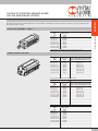
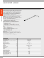
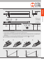
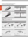
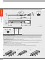
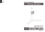
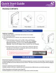
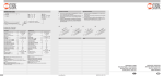
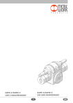
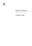
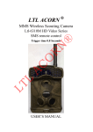
ACTUATORS
POSITION SENSOR
1
2
ACTUATORS
PAGE 4
P LTS POSITION SENSOR
PAGE 5
P LTL POSITION SENSOR PAGE9
P LTE POSITION SENSOR
PAGE12
SUMMARY
P INTRODUCTION
ACTUATORS
SUMMARY
3
ACTUATORS
INTRODUCTION
INTRODUCTION
Magnetic position sensors are used for measuring the linear stroke of
actuators. The position of the piston is measured without contact and given
via a configurable analogue output signal, as voltage (0-10 V) or current
(4-20 mA).
Our position sensors are divided into three types: LTS, LTL and LTE.
The LTS position sensors can be used for various product families with
strokes up to 256 mm. It is used for ISO 15552 TYPE A and SERIES 3
cylinders, CMPC and ISO 21287 LINER compact cylinders, ELEKTRO ISO
15552 electric cylinders and R3 rotary actuators.
With ISO 15552 TYPE A and ELEKTRO ISO 15552 cylinders, the other
two types of position sensors, LTL and LTE, can be used when the stroke
exceeds 256 mm (see table).
LTS
LTL
LTE
RANGE OF APPLICATION OF LTS, LTL AND LTE SENSORS ON ISO 15552 TYPE A CYLINDERS
Bore
mm
32
40
50
63
80
100
125
NOTES
4
LTS
Strokes from 0 to 256 mm
YES
YES
YES
YES
YES
YES
YES
LTL
Strokes from 257 to 503 mm
NO
NO
YES
YES
YES
YES
YES
LTE
Strokes from 150 to 500 mm
YES
YES
YES
NO
NO
NO
NO
ACTUATORS
LTS POSITION SENSOR
LTS POSITION SENSOR
The LTS is a magnetic position sensor for measuring linear strokes of
actuators. The position of the piston is measured without contact and
given via a configurable analogue output signal, as voltage or current.
The body of the LTS is very compact, so it can be used in applications
where limited space is available.
This position sensor can measure the strokes of various families of
actuators up to 256 mm.
Correct operation requires a magnetic field strength of between 4 and
30 mT.
The measurement range can be regulated accurately using the Teach-in
button (zero point and end point). Teach-in can be performed regardless
of the polarity of the magnetic field and the position of the sensor. The
yellow ON light comes on when the piston is in measuring range.
The position sensor is out of the measuring range when:
• the yellow light is off; and
• the voltage signal is 11V (range 0-10V) or the current 3 mA
(range 4-20 mA).
TECHNICAL DATA
Measuring length (± 1 mm)
Electrical connection
Electromagnetic compatibility in accordance with standard
Sample time
IEC 60068-2-6 shock test
IEC 60068-2-6 vibration test
Maximum displacement speed
Linearity*
Resolution
Repeatability
Operating temperature
Index of protection
Protection class
Voltage
Black current (without load)
Analogue output (voltage)
Out-of-range analogue output
Analogue output (current)
Out-of-range analogue output
Max. load resistance (current output)
Min. load resistance (voltage output)
Polarity inversion protection
Short-circuit protection
Overload protection
mm
ms
m/s
mm
mm
mm
°C
V
mA
V
V
mA
mA
Ω
Ω
from 0 to 256
M8x1 – 4 pin
EN 60947-5-7
1
30 g, 11 ms
10 Hz ... 55 Hz, 1 mm
<3
0.3
0.03 % FSR (≥ 0.05 mm)
0.06 % FSR (≥ 0.1 mm)
–20 to +70
IP 67
III
15 - 30
< 25
0 to 10
11
4 to 20
3
500
2000
YES
YES
YES
* In some applications, linearity may be higher than the value
indicated.
5
LTS POSITION SENSOR
ACTUATORS
DIMENSIONS AND ELECTRICAL CONNECTION
LTS
LED (yellow)
TEACH-IN button
Fixing screw
L1 = Measuring range
L2 = Total length
L3 = Fixing screws centre
Type
LTS-032
LTS-064
LTS-096
LTS-128
LTS-160
LTS-192
LTS-224
LTS-256
L1 [mm]
32
64
96
128
160
192
224
256
L2 [mm]
45
77
109
141
173
205
237
269
PIN
1
2
3
4
L3 [mm]
40
72
104
136
168
200
232
264
Colour
Brown
White
Blue
Black
Function
Positive
Current output
Negative
Voltage output
FIXING ON THE ACTUATOR AND START-UP
1. Connect the position sensor to the power supply using the M8x1 4-pin connector, wiring the voltage or the current output;
2. Insert the position sensor in one of the T-slots in the actuator (fig. A) and tighten the two screws using the key provided (fig. B);
3. If you wish to determine a specific measuring range, perform the procedure with the Teach-In button (see instruction manual).
N.B. If a measuring range is not set, the maximum range is used automatically.
GRAPH OF THE VOLTAGE OR CURRENT ANALOGUE OUTPUT SIGNAL VALUE AND THE OUT-OF-RANGE VALUE
U
11 V
10 V
Out of range
Out of range
I
20 mA
Out of range
Out of range
4 mA
3 mA
0V
Zero position
6
Final position
Zero position
Final position
ACTUATORS
CHOICE OF POSITION SENSOR BASED
ON THE MEASURING STROKE
The tables below show the recommended position sensors model for some families of actuators. For other products it is necessary to determine whether the LTS operates correctly.
ISO 15552 TYPE A CYLINDERS – SERIES 3
LTS POSITION SENSOR
Ø 32* - Ø 40 - Ø 50 - Ø 63 - Ø 80 - Ø 100 - Ø 125
Stroke
Position sensors
[mm]
model
up to 32
LTS-032
from 33 to 64
LTS-064
from 65 to 96
LTS-096
from 97 to 128
LTS-128
from 129 to 160
LTS-160
from 161 to 192
LTS-192
from 193 to 224
LTS-224
from 225 to 256
LTS-256
* ISO 15552 series 3 cylinders cannot be used for strokes up to 3 mm.
COMPACT CYLINDERS - SERIES CMPC
Stroke
[mm]
up to 32
from 34 to 64
from 66 to 96
from 98 to 128
from 130 to 160
from 162 to 192
from 194 to 224
from 226 to 256
Ø 12- Ø 16 - Ø 20
Position sensors Strokes for which the LTS projects beyond the
cylinder heads, despite being fixed correctly.
model
LTS-032
LTS-064
from 34 to 38
LTS-096
from 66 to 70
LTS-128
from 98 to 102
LTS-160
from 130 to 134
LTS-192
from 162 to 166
LTS-224
from 194 to 198
LTS-256
from 226 to 230
The LTS cannot be used with some strokes (e.g. 33 mm).
Stroke
[mm]
up to 32
from 33 to 64
from 65 to 96
from 97 to 128
from 129 to 160
from 161 to 192
from 193 to 224
from 225 to 256
Stroke
[mm]
up to 32
from 33 to 64
from 65 to 96
from 97 to 128
from 129 to 160
from 161 to 192
from 193 to 224
from 225 to 256
Position sensors
model
LTS-032
LTS-064
LTS-096
LTS-128
LTS-160
LTS-192
LTS-224
LTS-256
Ø 25
Strokes for which the LTS projects beyond the
cylinder heads, despite being fixed correctly.
from 33 to 37
from 65 to 69
from 97 to 101
from 129 to 133
from 161 to 165
from 193 to 197
from 225 to 229
Ø 32 - Ø 40 - Ø 50 - Ø 63 - Ø 80 - Ø 100
Position sensors
model
LTS-032
LTS-064
LTS-096
LTS-128
LTS-160
LTS-192
LTS-224
LTS-256
7
ACTUATORS
ISO 21287 COMPACT CYLINDERS – LINER SERIES
LTS POSITION SENSOR
Stroke
[mm]
up to 32
from 35 to 64
from 67 to 96
from 99 to 128
from 131 to 160
from 163 to 192
from 195 to 224
from 227 to 256
Position sensor
model
LTS-032
LTS-064
LTS-096
LTS-128
LTS-160
LTS-192
LTS-224
LTS-256
Ø 20
Strokes for which the LTS projects beyond the
cylinder heads, despite being fixed correctly.
from 39 to 64
from 71 to 96
from 103 to 128
from 135 to 160
from 167 to 192
from 199 to 224
from 231 to 256
The LTS cannot be used with some strokes (e.g. 33 mm).
Stroke
[mm]
up to 32
from 33 to 64
from 65 to 96
from 97 to 128
from 129 to 160
from 161 to 192
from 193 to 224
from 225 to 256
Stroke
[mm]
up to 32
from 33 to 64
from 65 to 96
from 97 to 128
from 129 to 160
from 161 to 192
from 193 to 224
from 225 to 256
Position sensor
model
LTS-032
LTS-064
LTS-096
LTS-128
LTS-160
LTS-192
LTS-224
LTS-256
Ø 25
Strokes for which the LTS projects beyond the
cylinder heads, despite being fixed correctly.
from 37 to 64
from 69 to 96
from 101 to 128
from 133 to 160
from 165 to 192
from 197 to 224
from 229 to 256
Ø 32 - Ø 40 - Ø 50 - Ø 63 - Ø 80 - Ø 100
Position sensor
model
LTS-032
LTS-064
LTS-096
LTS-128
LTS-160
LTS-192
LTS-224
LTS-256
ROTARY ACTUATORS - SERIES R3
Bore
[mm]
16
20
22
25
30
40
Position sensor
model
LTS-64
LTS-64
LTS-64
LTS-64
LTS-64
LTS-64
ELECTRIC CYLINDER SERIES ELEKTRO ISO 15552
Bore
[mm]
up to 32
from 33 to 64
from 65 to 96
from 97 to 128
from 129 to 160
from 161 to 192
from 193 to 224
from 225 to 256
8
Ø 32 - Ø 50 - Ø 63
Position sensor
model
LTS-032
LTS-064
LTS-096
LTS-128
LTS-160
LTS-192
LTS-224
LTS-256
ORDERING CODES
ACTUATORS
Description
LTS-032 position sensor with M8 4-PIN 0.3 m connector
LTS-064 position sensor with M8 4-PIN 0.3 m connector
LTS-096 position sensor with M8 4-PIN 0.3 m connector
LTS-128 position sensor with M8 4-PIN 0.3 m connector
LTS-160 position sensor with M8 4-PIN 0.3 m connector
LTS-192 position sensor with M8 4-PIN 0.3 m connector
LTS-224 position sensor with M8 4-PIN 0.3 m connector
LTS-256 position sensor with M8 4-PIN 0.3 m connector
LTS POSITION SENSOR
Code
W0950000470
W0950000471
W0950000472
W0950000473
W0950000474
W0950000475
W0950000476
W0950000477
ACCESSORIES
STRAIGHT M8 CONNECTORS
Pin
1
2
3
4
Code
0240009100
0240009101
Description
M8 4-pin connector – female, straight L = 2 m
M8 4-pin connector – female, straight L = 5 m
Code
0240009102
0240009103
Description
M8 4-pin connector – female, 90° angle L = 2 m
M8 4-pin connector – female, 90° angle L = 5 m
Cable colour
Brown
White
Blue
Black
90° M8 CONNECTORS
Pin
1
2
3
4
Cable colour
Brown
White
Blue
Black
NOTES
9
LTL POSITION SENSOR
ACTUATORS
LTL POSITION SENSOR
The LTL position sensor uses an array of Hall sensors to measure positions
without contact, thanks to the presence of a magnet inside the cylinder.
It uses a smart algorithm to adapt dynamically to the magnets during
operation, so that the output signal is always linear and reproducible.
This technology allows the position sensor to adapt dynamically to
changes in the intensity of the magnetic field connected with ageing of
the magnet and the different operating temperatures.
A magnetic field intensity of between 2 and 15 mT is required for correct
operation.
The LTL can be set by means of a TEACH-PAD capacitive button that
allows rapid actuation of the position sensor and adaptation to the user’s
requirements. Just press slightly with the fingers to:
• select an output current (4-20 mA) or output voltage (0-10 V);
• establish the desired measuring range;
• reset the position sensor to the factory setting.
The button is designed to prevent unintentional changes to the
parameters.
The position sensor is out of the measuring range when:
• the yellow light is off; and
• the voltage signal is 11V (range 0-10V) or the current 3 mA
(range 4-20 mA).
LED1 (operating light) comes on when the piston is in the measuring
range:
• yellow on - optimal signal power;
• yellow on and red flashing - signal power not optimal.
LED2 tells you which analogue output is active:
• green – voltage analogue output;
• blue – current analogue output.
The position sensor is secured by means of brackets near one of the
actuator T-slots.
The LTL position sensor is applied to ISO 15552 type A cylinders, and
electric cylinders serie ELEKTRO ISO 15552.
For longer strokes please contact our sales department.
TECHNICAL DATA
Measuring length (± 1 mm)
Electrical connection
Electromagnetic compatibility in accordance with standard
Sample time
IEC 60068-2-6 shock test
IEC 60068-2-6 vibration test
Maximum displacement speed
Linearity
Resolution
Repeatability
Operating temperature
Index of protection
Protection class
Voltage
Black current (without load)
Analogue output (voltage)
Out-of-range analogue output
Analogue output (current)
Out-of-range analogue output
Max. load resistance (current output)
Min. load resistance (voltage output)
Polarity inversion protection
Short-circuit protection
10
mm
ms
m/s
mm
mm
mm
°C
V
mA
V
V
mA
mA
Ω
Ω
from 257 to 503
M8x1 – 4 pin
EN 60947-5-7
1.15
30 g, 11 ms
10 Hz ... 55 Hz, 1 mm
<3
0.5
0.03 % FSR (≥ 0.06 mm)
0.06 % FSR (≥ 0.1 mm)
–20 to +70
IP 65, IP 67
III
15 to 30
< 35
0 to 10
11
4 to 20
3
< 500
> 2000
YES
YES
L1
3
2
1,3
1
LTL
TEACH PAD button
LED1 (yellow/red)
LED2 (blue/green)
L = Total length
L1 = Measuring range
Type
LTL-287
LTL-359
LTL-431
LTL-503
L [mm]
289
361
433
505
PIN
1
2
3
4
L1 [mm]
287
359
431
503
Colour
Brown
White
Blue
Black
LTL POSITION SENSOR
7,5
2,6
0,7
4
20 ±0,20
ACTUATORS
L
8,2
19,5
14 ±0,20
DIMENSIONS AND ELECTRICAL CONNECTION
Function
Voltage +
Current output
Voltage Voltage output
FIXING ON THE ACTUATOR AND START-UP
1. Position the brackets (code W0950000721) in one of the T-slots in the cylinder liner (fig. A);
2. Fix the brackets in the position sensor slot at least 30 mm from the ends of the position sensor (fig. B). The brackets are used to adjust the position
along the axis of the piston rod, including perpendicular to the T-slot (fig. C). This allows you to fix the position sensor in as central a position as
possible (fig. D);
3. Connect the position sensor to the power supply using the M8x1 4-pin connector, wiring the voltage or the current output;
4. If you wish to determine a specific measuring range, perform the procedure with the Teach pad ( ) (see user manual).
N.B. If a measuring range is not set, the maximum range is used automatically.
30 min
GRAPH OF THE VOLTAGE OR CURRENT ANALOGUE OUTPUT SIGNAL VALUE AND THE OUT-OF-RANGE VALUE
U
11 V
10 V
Out of range
Out of range
I
20 mA
Out of range
Out of range
4 mA
3 mA
0V
Zero position
Final position
Zero position
Final position
11
CHOICE OF POSITION SENSOR BASED ON
THE ACTUATOR MEASURING STROKE
LTL POSITION SENSOR
ACTUATORS
ISO 15552 TYPE A CYLINDERS
Ø 50 - Ø 63 - Ø 80 - Ø 100 - Ø 125
Measuring stroke [mm]
Position sensor model
from 255 to 287
LTL-287
from 288 to 359
LTL-359
from 360 to 431
LTL-431
from 432 to 503
LTL-503
ELECTRIC CYLINDER SERIES ELEKTRO ISO 15552
Ø 32 - Ø 50 - Ø 63
Measuring stroke [mm]
from 255 to 287
from 288 to 359
from 360 to 431
from 432 to 503
Position sensor model
LTL-287
LTL-359
LTL-431
LTL-503
ORDERING CODE
Code
W0950000478
W0950000479
W0950000480
W0950000481
Description
LTL-287 Position sensor with M8 4-PIN 0.3 m connector
LTL-359 Position sensor with M8 4-PIN 0.3 m connector
LTL-431 Position sensor with M8 4-PIN 0.3 m connector
LTL-503 Position sensor with M8 4-PIN 0.3 m connector
ACCESSORIES
STRAIGHT M8 CONNECTORS
90° M8 CONNECTORS
Pin
1
2
3
4
Code
0240009100
0240009101
Description
M8 4-pin connector – female, straight L = 2 m
M8 4-pin connector – female, straight L = 5 m
Pin
1
2
3
4
Code
0240009102
0240009103
SLOTTED FIXING PLATE WITH INSERTION FROM ABOVE
Code
W0950000721
Code
0950003001
Description
Bracket for mounting LTL on cylinder with T-slot
Cable colour
Brown
White
Blue
Black
Description
M8 4-pin connector – female, 90° angle L = 2 m
M8 4-pin connector – female, 90° angle L = 5 m
T-SLOT BRACKET
Bracket for fixing the LTL position sensor in the T-slot of the actuator.
12
Cable colour
Brown
White
Blue
Black
Description
M4 T-slotted fixing plate
Weight [g]
4
Note: Individually packed.
N.B. To be used with the T-slot bracket W0950000721 when the T-slot is not a through one
(e.g. in cylinders series ELEKTRO ISO 15552).
ACTUATORS
LTE POSITION SENSOR
LTE POSITION SENSOR
The LTE is a in-line position sensor with an innovative magnetostrictive
solution and no electric contact.
The absence of an electric contact on the slide eliminates the problem
of wear and guarantees a virtually unlimited life. The position sensor
is fixed in one of the sensor slots in the actuator liner by means of two
screws. Actuators to which the position sensor is applied are standard
and require no adaptation, they just have to be the magnetic version. The
position sensor automatically detects the position of the magnets inside the
cylinder.
The LTE is applied to ISO 15552 type A cylinders with the same stroke
and the measuring length.
For longer strokes please contact our sales department.
TECHNICAL DATA
Measuring length
Electrical connection
Sample time
DIN IEC68T2-27 shock test
DIN IEC68T2-6 vibration test
Maximum displacement speed
Maximum acceleration
Resolution
Linearity*
Maximum repeatability
Maximum hysteresis
Operating temperature
Storage temperature
Temperature coefficient
Index of protection
Spam
Voltage
Electrical zero
Maximum ripple voltage
Output current consumption
Output load
Max. output value
Alarm output value
Electrical insulation
Polarity inversion protection
Short-circuit protection
Overload protection
mm
ms
m/s
m/s2
mm
mm
mm
°C
°C
V
V
mA
kΩ
V
V
V
150 - 200 - 250 - 300 - 350 - 400 - 450 - 500
M8x1 – 4 pin
1 for measuring lengths up to 600 mm, 1.5 for greater lengths
100 g - 11 ms - single stroke
12g / 10 … 2000 Hz
≤ 10
≤ 100
Endless
≤ ±0.2% f.s. (min ±1 mm)
≤ 0.05
≤ 0.2
0 to +50
-40 to +100
≤ ±0.01% f.s./°C (min 0.015 mm/°C)
IP 65
9 VDC ± 100 mV max
24 ± 20%
0.8
1 Vpp
35
≥ 10
12
10.5
50
YES
YES
YES
* In some applications, linearity may be higher than the value
indicated.
13
LTE POSITION SENSOR
ACTUATORS
DIMENSIONS AND ELECTRICAL CONNECTION
L = Total length
PIN
1
2
3
4
Colour
Brown
White
Blue
Black
Function
Voltage +
Output
Voltage Screen
FIXING ON THE ACTUATOR AND START-UP
The position sensor can be fixed on the cylinder using either two M4 T-slot plates for vertical insertion + 2 M4x14 hexagon socket countersunk head
screws (code 0950003003) or two blocks + 2 M4x14 hexagon socket countersunk head screws (code 0950003050). If the cylinder head projects
from the liner, position one or more spacers.
The installation procedure is as follows:
1. Insert either the fixing blocks or the plates in the T-slots in the cylinder (fig. A);
2. Mount the position sensor on the cylinder, aligning the reference mark a) with the end of the liner (Fig. A). Do up the screws loosely and retract the
piston rod completely (Fig. B).
3. Connect the voltage or current analogue output, power on the position sensor and wait at least 1 second for the magnet orientation to be
recognized.
4. Slide the position sensor along until the zero value reading is 0.8V.
5. Tighten the two M4x14 screws on the securing element inserted in the T-slot (Fig. C).
The end of the position sensor may project a certain amount from the end of the cylinder head, depending on the type of cylinder.
14
A [mm]
~ 16
~ 12
~ 12
N.B. Projection by a zero value equal to 0.8V
CHOICE OF POSITION SENSOR BASED ON THE ACTUATOR MEASURING STROKE
LTE POSITION SENSOR
Bore [mm]
32
40
50
ACTUATORS
PROJECTION OF POSITION SENSOR ON ISO 15552 TYPE A CYLINDERS
ISO 15552 TYPE A CYLINDERS
Ø 32 - Ø 40 - Ø 50
Measuring stroke [mm]
Position sensor model
150
LTE-150
200
LTE-200
250
LTE-250
300
LTE-300
350
LTE-350
400
LTE-400
450
LTE-450
500
LTE-500
ORDERING CODE
Code
W0950000482
W0950000483
W0950000484
W0950000485
W0950000486
W0950000487
W0950000488
W0950000489
Description Metal Work
LTE-150 position sensor
LTE-200 position sensor
LTE-250 position sensor
LTE-300 position sensor
LTE-350 position sensor
LTE-400 position sensor
LTE-450 position sensor
LTE-500 position sensor
Description GEFRAN
ONPP-A-S-0150-N
ONPP-A-S-0200-N
ONPP-A-S-0250-N
ONPP-A-S-0300-N
ONPP-A-S-0350-N
ONPP-A-S-0400-N
ONPP-A-S-0450-N
ONPP-A-S-0500-N
NOTES
15
ACCESSORIES
LTE POSITION SENSOR
ACTUATORS
STRAIGHT M8 CONNECTORS
Pin
1
2
3
4
Code
0240009100
0240009101
Description
M8 4-pin connector – female, straight L = 2 m
M8 4-pin connector – female, straight L = 5 m
Code
0240009102
0240009103
Description
M8 4-pin connector – female, 90° angle L = 2 m
M8 4-pin connector – female, 90° angle L = 5 m
Code
0950003003
Description
M4 T-slotted fixing plate
Cable colour
Brown
White
Blue
Black
90° M8 CONNECTORS
Pin
1
2
3
4
Cable colour
Brown
White
Blue
Black
SLOTTED FIXING PLATE WITH INSERTION FROM ABOVE
Weight [g]
4
Note: Note: 2 items plus 2 M4x14 screws per pack
SLOTTED FIXING PLATE WITH LATERAL INSERTION
Code
0950003050
Description
Fixing block
Weight [g]
5
Note: Note: 2 items plus 2 M4x14 screws per pack
NOTES
16
www.metalwork.eu
Dimensions and data shown in this catalogue are subject to variations at any time without prior notice
MNWS01089_GB - IM00_02/2014