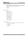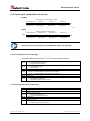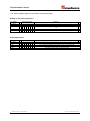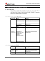
1
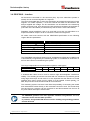
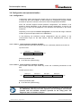
Rotary Encoders Linear Encoders Motion System + CAMS CE-65 • Software/Support CD: 490-01001 - Soft-No.: 490-00406 437656 • Basic safety instructions • Installation • Commissioning • Configuration / Parameterization • Troubleshooting / Diagnostic options TR - ECE - BA - GB - 0032 - 00 Single-Turn / Multi-Turn Absolute rotary encoder series CE-65 with PROFIBUS-DP interface 09/19/2011 User Manual TR-Electronic GmbH D-78647 Trossingen Eglishalde 6 Tel.: (0049) 07425/228-0 Fax: (0049) 07425/228-33 E-mail: [email protected] http://www.tr-electronic.de Copyright protection This Manual, including the illustrations contained therein, is subject to copyright protection. Use of this Manual by third parties in contravention of copyright regulations is forbidden. Reproduction, translation as well as electronic and photographic archiving and modification require the written content of the manufacturer. Offenders will be liable for damages. Subject to amendments Any technical changes that serve the purpose of technical progress, reserved. Document information Release date/Rev. date: Document rev. no.: File name: Author: 09/19/2011 TR - ECE - BA - GB - 0032 - 00 TR-ECE-BA-GB-0032-00.DOC MÜJ Font styles Italic or bold font styles are used for the title of a document or are used for highlighting. Courier font displays text, which is visible on the display or screen and software menu selections. < > indicates keys on your computer keyboard (such as <RETURN>). Trademarks SIMATIC S5/7, STEP-5/7 and COM-ET-200 are registered trademarks of the SIEMENS corporation. PROFIBUS-DP and the PROFIBUS logo are registered trademarks of the Profibus User Organization (PNO) TR-Electronic GmbH 2011, All Rights Reserved Page 2 of 39 Printed in the Federal Republic of Germany TR - ECE - BA - GB - 0032 - 00 09/19/2011 Table of Contents Table of Contents Table of Contents .......................................................................................................................................... 3 Revision index ............................................................................................................................................... 5 1 Basic safety instructions ........................................................................................................................... 6 1.1 Definition of symbols and instructions ............................................................................................... 6 1.2 Obligation of the operator before start-up ......................................................................................... 6 1.3 General risks when using the product ............................................................................................... 7 1.4 Proper use ......................................................................................................................................... 7 1.5 Warranty and liability ......................................................................................................................... 8 1.6 Organizational measures ................................................................................................................... 9 1.7 Personnel qualification; obligations ................................................................................................... 9 1.8 Safety information's ........................................................................................................................... 10 2 Transportation / device data ..................................................................................................................... 11 2.1 Transportation / storage..................................................................................................................... 11 2.2 Technical data ................................................................................................................................... 12 2.2.1 Electrical ratings................................................................................................................. 12 2.2.2 Mechanical ratings ............................................................................................................. 12 2.3 Assembly ........................................................................................................................................... 13 2.4 Connecting the Cable Screening to the Bus-Cap.............................................................................. 14 3 Device description / start-up ..................................................................................................................... 15 3.1 PNO identification number ................................................................................................................. 15 3.2 PNO certificate ................................................................................................................................... 15 3.3 PNO encoder profile .......................................................................................................................... 15 3.4 Operating requirements ..................................................................................................................... 15 3.5 Setting the station address ................................................................................................................ 15 3.6 PROFIBUS – interface....................................................................................................................... 16 3.7 Device master file .............................................................................................................................. 17 3.8 Configuration and parameterization .................................................................................................. 18 3.8.1 Configuration...................................................................................................................... 18 3.8.1.1 Class 1 16-bit resolution, identifier D0 (HEX): ............................................................................................ 18 3.8.1.2 Class 1 32-bit resolution, identifier D1 (HEX): ............................................................................................ 18 3.8.1.3 Class 2 16-bit resolution, identifier F0 (HEX): ............................................................................................ 19 3.8.1.4 Class 2 32-bit resolution, identifier F1 (HEX): ............................................................................................ 19 3.8.1.5 TR-mode position, identifier F1 (HEX): ......................................................................................................... 20 3.8.1.6 TR-mode position + cam + velocity, identifier F1 (HEX): .............................................................................. 21 3.8.2 Parameterization ................................................................................................................ 22 3.8.2.1 Code sequence (Zählrichtung): .................................................................................................................... 22 3.8.2.2 Class 2 functionality (Klasse 2 Funktionen):................................................................................................. 22 3.8.2.3 Commissioning diagnostic control: ............................................................................................................... 22 3.8.2.4 Scaling function control (Skalierungsfunktion):............................................................................................. 22 3.8.2.5 Measuring units per revolution (Anzahl Schritte pro Umdrehung): ............................................................... 22 3.8.2.6 Total measuring range [units] (Messlänge in Schritten) ............................................................................... 23 3.8.2.7 Revolutions numerator (Umdrehungen Zähler) ............................................................................................ 23 3.8.2.8 Revolutions denominator (Umdrehungen Nenner) ....................................................................................... 23 3.8.2.9 Code PROFIBUS interface (Code für PROFIBUS-Schnittstelle): ................................................................. 23 Printed in the Federal Republic of Germany 09/19/2011 TR-Electronic GmbH 2011, All Rights Reserved TR - ECE - BA - GB - 0032 - 00 Page 3 of 39 Table of Contents 3.8.2.10 Preset 1 value [units] .................................................................................................................................. 24 3.8.2.11 Preset 2 value [units] .................................................................................................................................. 24 3.8.2.12 Short diagnostic (16 byte) ........................................................................................................................... 25 3.8.2.13 Cams (Nocken) ........................................................................................................................................... 25 3.8.2.14 Speed [1/n rpm] .......................................................................................................................................... 25 3.8.3 Scaling function.................................................................................................................. 26 3.8.3.1 Nominal configurations PNO Class 1+2 ....................................................................................................... 26 3.8.3.2 Nominal configuration TR-mode position and TR-mode position+cam+velocity .......................................... 27 3.9 Preset adjustment .............................................................................................................................. 28 3.10 Input/output configuration for teach-in ............................................................................................. 29 3.10.1.1 Assignment of the status byte .................................................................................................................... 29 3.10.1.2 Assignment of the control byte ................................................................................................................... 29 4 Trouble-shooting and diagnostic facilities .............................................................................................. 31 4.1 Visual indicators ................................................................................................................................. 31 4.1.1 Indicator states, green LED (STAT)................................................................................... 31 4.1.2 Indicator states, red LED (BF) ........................................................................................... 31 4.2 How to use the PROFIBUS diagnostics ............................................................................................ 32 4.2.1 Standard diagnosis ............................................................................................................ 32 4.2.1.1 Station status 1 ............................................................................................................................................. 33 4.2.1.2 Station status 2 ............................................................................................................................................. 33 4.2.1.3 Station status 3 ............................................................................................................................................. 33 4.2.1.4 Master address ............................................................................................................................................. 34 4.2.1.5 Manufacturer's identifier ............................................................................................................................... 34 4.2.1.6 Length (in byte) of extended diagnosis ......................................................................................................... 34 4.2.2 Extended diagnosis............................................................................................................ 35 4.2.2.1 Alarms .......................................................................................................................................................... 35 4.2.2.2 Operating status ........................................................................................................................................... 36 4.2.2.3 Encoder type ................................................................................................................................................ 36 4.2.2.4 Single-turn resolution.................................................................................................................................... 36 4.2.2.5 Number of resolvable revolutions ................................................................................................................. 36 4.2.2.6 Additional alarms .......................................................................................................................................... 36 4.2.2.7 Supported alarms ......................................................................................................................................... 37 4.2.2.8 Warnings ...................................................................................................................................................... 37 4.2.2.9 Supported warnings ...................................................................................................................................... 37 4.2.2.10 Profile version ............................................................................................................................................. 37 4.2.2.11 Software version ......................................................................................................................................... 38 4.2.2.12 Operating hour counter ............................................................................................................................... 38 4.2.2.13 Offset value ................................................................................................................................................ 38 4.2.2.14 Manufacturer-specific offset value .............................................................................................................. 38 4.2.2.15 Number of increments per revolution ......................................................................................................... 38 4.2.2.16 Measuring length in increments.................................................................................................................. 38 4.2.2.17 Serial number ............................................................................................................................................. 38 4.2.2.18 Manufacturer-specific diagnostics .............................................................................................................. 38 4.3 Other faults ........................................................................................................................................ 39 TR-Electronic GmbH 2011, All Rights Reserved Page 4 of 39 Printed in the Federal Republic of Germany TR - ECE - BA - GB - 0032 - 00 09/19/2011 Revision index Revision index Revision Date First release 09/19/2011 Printed in the Federal Republic of Germany 09/19/2011 Index 00 TR-Electronic GmbH 2011, All Rights Reserved TR - ECE - BA - GB - 0032 - 00 Page 5 of 39 Basic safety instructions 1 Basic safety instructions 1.1 Definition of symbols and instructions means that death or serious injury can occur if the required precautions are not met. means that minor injuries can occur if the required precautions are not met. means that damage to property can occur if the required precautions are not met. indicates important information or features and application tips for the product used. means that appropriate protective measures against ESD according to DIN EN 100 015-1 must be applied. (Equalizing the potential between the body and both the equipment ground and the housing ground by means of a high resistance (ca. 1 MOhm) e.g. with a commercially available ESD armband). 1.2 Obligation of the operator before start-up As an electronic device the measuring system is subject to the regulations of the EMC Directive. It is therefore only permitted to start up the measuring system if it has been established that the system/machine into which the measuring system is to be fitted satisfies the provisions of the EC EMC Directive, the harmonized standards, European standards or the corresponding national standards. TR-Electronic GmbH 2011, All Rights Reserved Page 6 of 39 Printed in the Federal Republic of Germany TR - ECE - BA - GB - 0032 - 00 09/19/2011 Basic safety instructions 1.3 General risks when using the product The product, hereinafter referred to as "the measuring system", is manufactured according to state-of-the-art technology and accepted safety rules. Nevertheless, improper use can pose a danger to life and limb of the user or third parties, or lead to impairment of the measuring system or other property! Only use the measuring system in a technically faultless state, and only for its designated use, taking safety and hazard aspects into consideration, and observing this User Manual! Faults which could threaten safety should be eliminated without delay! 1.4 Proper use The measuring system is used to measure angular motion and to condition the measurement data for the subsequent control of industrial control processes. Proper use also includes: observing all instructions in this User Manual, observing the nameplate and any prohibition or instruction symbols on the measuring system, observing the enclosed configurations etc., documentation, e.g. product insert, connector observing the operating instructions from the machine or system manufacturer, operating the measuring system within the limit values specified in the technical data. The following areas of use are especially forbidden: in environments where there is an explosive atmosphere for medical purposes Printed in the Federal Republic of Germany 09/19/2011 TR-Electronic GmbH 2011, All Rights Reserved TR - ECE - BA - GB - 0032 - 00 Page 7 of 39 Basic safety instructions Examples of typical fields of application at industrial process and control processes: Transfer machines Machine tools Gantry robots Assembly installations etc. ... Everywhere, where rotation or angular movements must be detected for evaluation Where there is a danger of physical injury and damage to property arising from jumps in the position of the measuring system! - As the measuring system does not constitute a safety component, a plausibility check of the measuring system values must be performed through the subsequent control system. - It is mandatory for the operator to integrate the measuring system into his own safety concept. 1.5 Warranty and liability The General Terms and Conditions ("Allgemeine Geschäftsbedingungen") of TRElectronic GmbH always apply. These are available to the operator with the Order Confirmation or when the contract is concluded at the latest. Warranty and liability claims in the case of personal injury or damage to property are excluded if they result from one or more of the following causes: Non-designated use of the measuring system. Improper assembly, installation, start-up and programming of the measuring system. Incorrectly undertaken work on the measuring system by unqualified personnel. Operation of the measuring system with technical defects. Mechanical or electrical modifications to the measuring systems undertaken autonomously. Repairs carried out autonomously. Third party interference and Acts of God. TR-Electronic GmbH 2011, All Rights Reserved Page 8 of 39 Printed in the Federal Republic of Germany TR - ECE - BA - GB - 0032 - 00 09/19/2011 Basic safety instructions 1.6 Organizational measures The User Manual must always be kept accessible at the place of use of the measuring system. In addition to the User Manual, generally applicable legal and other binding accident prevention and environmental protection regulations are to be observed and must be mediated. The respective applicable national, local and system-specific provisions and requirements must be observed and mediated. The operator is obliged to inform personnel on special operating features and requirements. The personnel instructed to work with the measuring system must have read and understood the User Manual, especially the chapter “Basic safety instructions” prior to commencing work. The nameplate and any prohibition or instruction symbols applied on the measuring system must always be maintained in a legible state. Do not undertake any mechanical or electrical modifications on the measuring system, apart from those explicitly described in this User Manual. Repairs may only be undertaken by the manufacturer or a facility or person authorized by the manufacturer. 1.7 Personnel qualification; obligations All work on the measuring system must only be carried out by qualified personnel. Qualified personnel includes persons, who, through their training, experience and instruction, as well as their knowledge of the relevant standards, provisions, accident prevention regulations and operating conditions, have been authorized by the persons responsible for the system to carry out the required work and are able to recognize and avoid potential hazards. The definition of “Qualified Personnel” also includes an understanding of the standards VDE 0105-100 and IEC 364 (source: e.g. Beuth Verlag GmbH, VDEVerlag GmbH). Define clear rules of responsibilities for the assembly, installation, start-up and operation. The obligation exists to provide supervision for trainee personnel ! Printed in the Federal Republic of Germany 09/19/2011 TR-Electronic GmbH 2011, All Rights Reserved TR - ECE - BA - GB - 0032 - 00 Page 9 of 39 Basic safety instructions 1.8 Safety information's - Destruction, damage or malfunctions of the measuring system and risk of physical injury! De-energize the system before carrying out wiring work or opening and closing electrical connections. - Do not carry out welding if the measuring system has already been wired up or is switched on. - Ensure that the area around the assembly site is protected from corrosive media (acid, etc.). - Avoid any shocks (e.g. hammer-blow) on the shaft while mounting. - Do not open the measuring system. The measuring system contains electrostatically endangered circuit elements and units which can be destroyed by an improper use. - Contacts of the measuring system connection contacts with the fingers are to be avoided, or the appropriate ESD protective measures are to be applied. Disposal If disposal has to be undertaken after the life span of the device, the respective applicable country-specific regulations are to be observed. TR-Electronic GmbH 2011, All Rights Reserved Page 10 of 39 Printed in the Federal Republic of Germany TR - ECE - BA - GB - 0032 - 00 09/19/2011 Transportation / device data 2 Transportation / device data 2.1 Transportation / storage Notes on transportation Do not drop the device or expose it to shocks or vibrations! Device contains an optical system with glass elements. Only use the original packaging! The wrong packaging material can cause damage to the device during transportation. Storage Storage temperature: -30 to +80°C Store in a dry place. Printed in the Federal Republic of Germany 09/19/2011 TR-Electronic GmbH 2011, All Rights Reserved TR - ECE - BA - GB - 0032 - 00 Page 11 of 39 Transportation / device data 2.2 Technical data 2.2.1 Electrical ratings Operating voltage: ..................................................... 11-27 V DC (+/- 5% residual ripple) Max. current consumption: ...................................... < 350 mA at 11 V DC, < 150 mA at 27 V DC Output capacity: ........................................................ Max. 25 bits Resolution: ................................................................. Max. 8192 increments per revolution (13 bits) Measuring range:....................................................... 8192 revolutions Output code: .............................................................. Binary Baud rate: ................................................................... 12 Mbps Encoder interface: ..................................................... PROFIBUS-DP acc. to DIN 19245 Part 1-3 Special features: ........................................................ Programming is performed via the parameterization message at the start-up of the encoder or PROFIBUSDP master CAM level: .................................................................. Low: 0…1 V, High: VDC – 2 V CAM current: .............................................................. 30 mA Operating temperature range: .................................. 0 to +60°C 2.2.2 Mechanical ratings Mechanically permissible speed: ............................. 6000 rpm Permissible shaft load: ............................................. 40 N axial, 60 N radial (at end of shaft) Minimum bearing lifetime: ........................................ Operating speed: ............................................ Shaft loading: .................................................. Operating temperature: ................................... Max. angular acceleration:........................................ 3.9 x 10¹⁰ revolutions at: 3000 rpm 20 N axial, 30 N radial (at end of shaft) 60°C 104 rad/s2 6 2 Moment of inertia: ..................................................... 2.5 x 10- kg m Starting torque at 20°C: ............................................ 2 Ncm Vibration loading (50-2000Hz): ................................. 100 m/s2 Shock loading (11ms): .............................................. 1000 m/s2 TR-Electronic GmbH 2011, All Rights Reserved Page 12 of 39 Printed in the Federal Republic of Germany TR - ECE - BA - GB - 0032 - 00 09/19/2011 Transportation / device data 2.3 Assembly Encoder shaft drive Encoders of the CE series are connected to the drive shaft by an elastic coupling which compensates for any deviations in the axial and radial direction between the encoder and drive shaft. This avoids excessive strain on the bearings. Couplings can be ordered on request. Flange mounting The centering collar with fit f7 centers the encoder in relation to the shaft. It is fixed to the machine by means of three screws in the flange (Fig. 1). Clamping bracket mounting The centering collar with fit f7 centers the encoder in relation to the shaft. The encoder is fixed by means of two clamping brackets (Fig. 2). Fig. 1 Coupling Absolute encoder Machine Fig. 2 Coupling Absolute encoder Machine Clamping bracket Printed in the Federal Republic of Germany 09/19/2011 TR-Electronic GmbH 2011, All Rights Reserved TR - ECE - BA - GB - 0032 - 00 Page 13 of 39 Transportation / device data 2.4 Connecting the Cable Screening to the Bus-Cap To prevent disturbance signals entering the encoder housing, we used cable screw glands with which it is possible to connect the screen on the inside. For this reason, no connection point for the screen is provided inside the cup-cap. Procedure: 1. Screw the cable screw gland into the housing. 2. Dismount the compression nut (1) and the terminal holder (2). 3. Push the compression nut (1) and the terminal holder (2) over the cable. 4. Strip the cable; push back the braiding around the terminal holder (2) such that the braiding goes over the inner O-ring (3) and does not lie over the cylindrical section or the torsional bars. 5. Insert the terminal holder (2) into the intermediate gland (4) such that the torsional bars fit into the intended lengthwise grooves in the intermediate gland (4). 6. Screw the compression nut (1) to the intermediate gland (4). Part 1 Compression nut Part 2 Terminal holder Part 3 Inner O-ring Part 4 Intermediate gland TR-Electronic GmbH 2011, All Rights Reserved Page 14 of 39 Printed in the Federal Republic of Germany TR - ECE - BA - GB - 0032 - 00 09/19/2011 Device description / start-up 3 Device description / start-up 3.1 PNO identification number The encoder has the PNO ID number AAAB (hex). This number is reserved and filed with the PNO. 3.2 PNO certificate The encoder has passed a certification test by an independent test laboratory of the Profibus User Organization and is certified under the number Z00319. The relevant documents are held by TR Electronic and the PNO. 3.3 PNO encoder profile The Profibus User Organization has issued an encoder profile defining the structure of an encoder on the Profibus. A copy of this profile can be obtained for a fee from the PNO office. Details of prices are available exclusively by the Profibus User Organization. 3.4 Operating requirements Theoretically, the encoder can be connected to any Profibus-DP network, provided the PROFIBUS-DP master is capable of transmitting a parameter message. Similarly, the configuration software should be able to display the parameter structure specified in the device master file in order to allow the parameters to be entered. If this is not the case, the encoder cannot be programmed and runs on the bus with the maximum resolution, and without the possibility of scaling or adjustment as Class-1 encoder. TR Electronic supplies a Software/Support CD containing the device master file (.GSD) and a type file (.200) for users with SIEMENS masters. If the CD is not enclosed with this documentation, it can be purchased by order number: 490-01001, Soft-No.: 490-00406. For details of how to integrate the encoder into the interface of the DP master configuration software, please refer to the relevant documentation. 3.5 Setting the station address The station address of the encoder is set exclusively via the rotary switch in the cover containing the connecting terminals. When the terminals are viewed from above (outgoing cable facing downwards), the left-hand switch sets the tens and the righthand switch the units of the station address. The addressing of the encoder is limited within the Profibus address area. Valid station addresses are 3 - 99. If an invalid station address is set, the device will not start up and the LEDs will not be illuminated. Printed in the Federal Republic of Germany 09/19/2011 TR-Electronic GmbH 2011, All Rights Reserved TR - ECE - BA - GB - 0032 - 00 Page 15 of 39 Device description / start-up 3.6 PROFIBUS – interface All devices are connected in a bus structure (line). Up to 32 subscribers (master or slaves) can be connected together in a segment. The bus is terminated with an active bus termination at the beginning and end of each segment. For stable operation, it must be ensured that both bus terminations are always supplied with voltage. The bus termination can be switched in the measuring system connector hood. As a general rule, both switches must always be switched on (if encoder is the last station) or switched off (if the encoder is not the last station). Repeaters (signal amplifiers) have to be used with more than 32 subscribers or to expand the network scope in order to connect the various bus segments. All cables used must conform with the PROFIBUS specification for the following copper data wire parameters: Parameter Cable type A Wave impedance in Operating capacitance (pF/m) Loop resistance ( /km) Wire diameter (mm) Wire cross-section (mm²) 135...165 at a frequency of 3...20 MHz 30 110 > 0.64 > 0.34 The PROFIBUS transmission speed may be set between 9.6 kBit/s and 12 Mbit/s and is automatically recognized by the measuring system. It is selected for all devices on the bus at the time of commissioning the system. The range is dependent on the transmission speed for cable type A: Baud rate (kbits/s) Range / Segment 9.6 19.2 93.75 187.5 500 1500 12000 1200 m 1200 m 1200 m 1000 m 400 m 200 m 100 m A shielded data cable must be used to achieve high electromagnetic interference stability. The shielding should be connected with low resistance to protective ground using large shield clips at both ends. It is also important that the data line is routed separate from power current carrying cables if at all possible. At data speed 1.5 Mbit, drop lines should be avoided under all circumstances. The measuring system connector hood offers the possibility of connecting the inward and outward data cables directly to the removable connector hood. This avoids drop lines and the bus connector can be connected to and disconnected from the bus at any time without interruption of data traffic. The PROFIBUS guidelines and other applicable standards and guidelines are to be observed to insure safe and stable operation! In particular, the applicable EMC directive and the shielding and grounding guidelines must be observed! TR-Electronic GmbH 2011, All Rights Reserved Page 16 of 39 Printed in the Federal Republic of Germany TR - ECE - BA - GB - 0032 - 00 09/19/2011 Device description / start-up 3.7 Device master file The device master file of the encoder has the filename *TR08AAAB.GSD. To find out how to integrate this file into the system configuration, please refer to the documentation of the configuration program for the Profibus master. The encoder also has a bitmap file named TRAAAB5N.BMP. * Usable as of COMPROFIBUS version 5.0 (S5) or STEP7 as of version 5.0 service pack 3 (S7). Printed in the Federal Republic of Germany 09/19/2011 TR-Electronic GmbH 2011, All Rights Reserved TR - ECE - BA - GB - 0032 - 00 Page 17 of 39 Device description / start-up 3.8 Configuration and parameterization 3.8.1 Configuration Configuration means specifying the length and type of process data and the manner in which they are to be handled. For this purpose, the configuration program usually provides an input list in which the user has to enter the appropriate identifiers. Since the encoder supports several possible configurations, the identifier to be entered is preset depending on the required nominal configuration, so that all you have to do is enter the I/O addresses. The identifiers are deposited in the device master file. Depending on the required nominal configuration, the encoder will assign a different number of input and output words on the PROFIBUS. In the following, the individual nominal configurations and the position of the communication bytes for the data transfer with the PROFIBUS-DP master are described. 3.8.1.1 Class 1 16-bit resolution, identifier D0 (HEX): The encoder uses one input word only, which is consistently transferred via the bus. Input word IW x Data byte 1 Data byte 0 MSB LSB Input byte x+0 Input byte x+1 Relevant parameter data: Count direction (Zählrichtung) 3.8.1.2 Class 1 32-bit resolution, identifier D1 (HEX): The encoder uses two input words only, which are consistently transferred via the bus. Double input word ID x Data byte 3 Data byte 2 Data byte 1 Data byte 0 Input byte x+0 Input byte x+1 Input byte x+2 Input byte x+3 MSB LSB Relevant parameter data: Count direction (Zählrichtung) In the case of configurations for CLASS 1, preset adjustment is not possible via the PROFIBUS, and only the code sequence can be changed. The encoder operates with the standard resolution specified on the rating plate. The diagnostic data are limited to 16 bytes. TR-Electronic GmbH 2011, All Rights Reserved Page 18 of 39 Printed in the Federal Republic of Germany TR - ECE - BA - GB - 0032 - 00 09/19/2011 Device description / start-up 3.8.1.3 Class 2 16-bit resolution, identifier F0 (HEX): The encoder uses one input word and one output word which are consistently transferred via the bus. Input word IW x Data byte 1 Data byte 0 MSB LSB Input byte x+0 Input byte x+1 Output word for preset adjustment OW x Data byte 1 MSB Data byte 0 P LSB Output byte x+0 Output byte x+1 Relevant parameter data: Count direction (Zählrichtung) Class 2 functionality (on/off) (Klasse 2 ein/ausschalten) Scaling function (on/off) (Skalierungsfunktion ein/ausschalten) Commissioning diagnostic control (on/off) (Selbstmeldende Diagnose ein/ausschalten) Measuring units per revolution (Schritte pro Umdrehung) Total measuring range (Messlänge in Schritten) 3.8.1.4 Class 2 32-bit resolution, identifier F1 (HEX): The encoder uses two input words and two output words which are consistently transferred via the bus. Double input word ID x Data byte 3 Data byte 2 Data byte 1 Data byte 0 Input byte x+0 Input byte x+1 Input byte x+2 Input byte x+3 MSB LSB Double output word for preset adjustment OD x Data byte 3 MSB Data byte 2 Data byte 1 Data byte 0 P Output byte x+0 LSB Output byte x+1 Output byte x+2 Output byte x+3 Relevant parameter data: Count direction (Zählrichtung) Class 2 functionality (on/off) (Klasse 2 ein/ausschalten) Scaling function (on/off) (Skalierungsfunktion ein/ausschalten) Commissioning diagnostic control (on/off) (Selbstmeldende Diagnose ein/ausschalten) Measuring units per revolution (Schritte pro Umdrehung) Total measuring range (Messlänge in Schritten) Printed in the Federal Republic of Germany 09/19/2011 TR-Electronic GmbH 2011, All Rights Reserved TR - ECE - BA - GB - 0032 - 00 Page 19 of 39 Device description / start-up 3.8.1.5 TR-mode position, identifier F1 (HEX): The encoder uses two input words and two output words which are consistently transferred via the bus. Double input word ID x Data byte 3 Data byte 2 Data byte 1 Data byte 0 MSB LSB Input byte x+0 Input byte x+1 Input byte x+2 Input byte x+3 Double output word for preset adjustment OD x Data byte 3 MSB Data byte 2 Data byte 1 Data byte 0 Output byte x+1 Output byte x+2 Output byte x+3 LSB P Output byte x+0 Relevant parameter data: Count direction (Zählrichtung) Comissioning diagnostic control (Diagnose Meldemodus ein/ausschalten) Total measuring range (Messlänge in Schritten) Revolutions numerator (Umdrehungen Zähler) Revolutions denominator (Umdrehungen Nenner) Code PROFIBUS interface (Ausgabecode der PROFIBUS-Schnittstelle) Preset 1 value (1. Presetvorwahlwert für 24V Eingänge) Preset 2 value (2. Presetvorwahlwert für 24V Eingänge) Short Diagnostics (Kurze Diagnose) TR-Electronic GmbH 2011, All Rights Reserved Page 20 of 39 Printed in the Federal Republic of Germany TR - ECE - BA - GB - 0032 - 00 09/19/2011 Device description / start-up 3.8.1.6 TR-mode position + cam + velocity, identifier F1 (HEX): The encoder uses two input words for the position plus a separate input word for the velocity, and two output words which are consistently transferred via the bus. The velocity is output with a sign in revolutions per minute and has an accuracy of +/- 1 rpm. Double input word ID x Data byte 3 Data byte 2 Data byte 1 Data byte 0 Input byte x+0 Input byte x+1 Input byte x+2 Input byte x+3 MSB LSB Input word IW x Data byte 1 Data byte 0 MSB LSB Input byte x+0 Input byte x+1 Double output word for preset adjustment OD x Data byte 3 MSB Data byte 2 Data byte 1 Data byte 0 P Output byte x+0 LSB Output byte x+1 Output byte x+2 Output byte x+3 Relevant parameter data: Count direction (Zählrichtung) Comissioning diagnostic control (Diagnose Meldemodus ein/ausschalten) Total measuring range (Messlänge in Schritten) Revolutions numerator (Umdrehungen Zähler) Revolutions denominator (Umdrehungen Nenner) Cam programming see chapter “Cams”, page 25 Code PROFIBUS interface (Ausgabecode der PROFIBUS-Schnittstelle) Preset 1 value (1. Presetvorwahlwert für 24V Eingänge) Preset 2 value (2. Presetvorwahlwert für 24V Eingänge) Short Diagnostics (Kurze Diagnose) Speed [1/n rpm] (Geschwindigkeit [1/n U/min]) The configurations designated "TR mode" are not compatible with the PNO encoder profile in terms of the parameter record. The scaling function prescribed by the PNO profile is a simple special case of a general gear. Due to the extended 'gear' scaling function, additional parameters are therefore necessary in order to describe the gear fully. In other words, the TR-specific modes represent an extension of the encoder function which is not restricted by its compatibility with the PROFIBUS-DP and certification. Printed in the Federal Republic of Germany 09/19/2011 TR-Electronic GmbH 2011, All Rights Reserved TR - ECE - BA - GB - 0032 - 00 Page 21 of 39 Device description / start-up 3.8.2 Parameterization Parameterization means providing a PROFIBUS-DP slave with certain information required for operating purposes before it begins the cyclical exchange of process data. For example, the encoder requires data concerning the resolution, count direction, preset values, etc. The configuration program for the PROFIBUS-DP master usually provides an input mask via which the user can enter the parameter data or select from lists. The structure of the input mask is stored in the device master file. The number and type of the parameters to be entered by the user depend on the chosen nominal configuration. 3.8.2.1 Code sequence (Zählrichtung): Defines the count direction of the encoder. Selection Increasing clockwise Increasing counter-clockwise (steigend im Uhrzeigersinn) = default (fallend im Uhrzeigersinn) 3.8.2.2 Class 2 functionality (Klasse 2 Funktionen): Defines the encoder's range of functions. "Class 2 deactivated" means that the encoder only performs Class 1 functions, does not scale the position value and is not adjustable. Selection No Yes (Class 2 functions deactivated) = default (Class 2 activated) 3.8.2.3 Commissioning diagnostic control: Defines whether the encoder outputs an extended diagnostic message. Selection Disabled Enabled (Commissioning diagnostic control deactivated) = default (Commissioning diagnostic control activated) 3.8.2.4 Scaling function control (Skalierungsfunktion): Defines whether the encoder scales the position on the basis of the subsequent parameter. If Class 2 is deactivated, it does not scale the position value and is not adjustable. Selection Disabled Enabled (scaling deactivated) = default (scaling activated) 3.8.2.5 Measuring units per revolution (Anzahl Schritte pro Umdrehung): Defines the number of increments displayed by the encoder for each revolution of the encoder shaft. Input Lower limit: Upper limit: Default value: 1 increment / revolution 8192 increments per revolution (depending on capacity marked on rating plate) 4096 TR-Electronic GmbH 2011, All Rights Reserved Page 22 of 39 Printed in the Federal Republic of Germany TR - ECE - BA - GB - 0032 - 00 09/19/2011 Device description / start-up 3.8.2.6 Total measuring range [units] (Messlänge in Schritten) This parameter defines the total number of increments displayed by the encoder before it starts again from zero. Inputs Lower limit 16 Upper limit 33554432 (depending on the total capacity, which is calculated by multiplying the max. number of increments per revolution and the maximum number of revolutions. These details are marked on the rating plate.) Default value: 16777216 3.8.2.7 Revolutions numerator (Umdrehungen Zähler) Together with the parameter Revolutions denominator, these parameters define the total number of revolutions displayed by the encoder before it starts again from zero. Inputs Lower limit Upper limit Default value: 1 62464 4096 3.8.2.8 Revolutions denominator (Umdrehungen Nenner) Together with the parameter Revolutions numerator, these parameters define the total number of revolutions displayed by the encoder before it starts again from zero. Lower limit Upper limit Default value: 1 100 1 3.8.2.9 Code PROFIBUS interface (Code für PROFIBUS-Schnittstelle): Defines the output code for the PROFIBUS interface. Selection Gray Binary (encoder supplies Gray code) (encoder supplies binary code) = default Printed in the Federal Republic of Germany 09/19/2011 TR-Electronic GmbH 2011, All Rights Reserved TR - ECE - BA - GB - 0032 - 00 Page 23 of 39 Device description / start-up 3.8.2.10 Preset 1 value [units] Risk of injury and damage to property by an actual value jump when the preset function is performed! The preset function should only be performed when the measuring system is at rest, otherwise the resulting actual value jump must be permitted in the program and application! This parameter defines the position value to which the encoder is adjusted with the leading edge of the 1st preset input. To suppress interference, however, the preset is only carried out if the preset signal is present without interruption during the entire response time of 30 ms. A re-execution of the preset is not possible until the input signal has been reset again and a filter time of 30 ms has been waited. The inputs depend on the total measuring length in increments Lower limit Upper limit Default value 0 total measuring length in increments - 1 1 3.8.2.11 Preset 2 value [units] Risk of injury and damage to property by an actual value jump when the preset function is performed! The preset function should only be performed when the measuring system is at rest, otherwise the resulting actual value jump must be permitted in the program and application! This parameter defines the position value to which the encoder is adjusted with the leading edge of the 2nd preset input. To suppress interference, however, the preset is only carried out if the preset signal is present without interruption during the entire response time of 30 ms. A re-execution of the preset is not possible until the input signal has been reset again and a filter time of 30 ms has been waited. The inputs depend on the total measuring length in increments Lower limit Upper limit Default value 0 total measuring length in increments - 1 2 TR-Electronic GmbH 2011, All Rights Reserved Page 24 of 39 Printed in the Federal Republic of Germany TR - ECE - BA - GB - 0032 - 00 09/19/2011 Device description / start-up 3.8.2.12 Short diagnostic (16 byte) With this parameter in the TR operation modes the number of diagnostic bytes can be limited from 6+51 bytes to 6+10 bytes. Therefore the encoder can be operated also to Profibus masters with older issue numbers in these modes. Selection No = default Yes 3.8.2.13 Cams (Nocken) Default value = 0 Output 1, Cam 1, start Output 1, Cam 1, stop : : Output 1, Cam 5, start Output 1, Cam 5, stop Output 2, Cam 1, start Output 2, Cam 1, stop : : Output 2, Cam 5, start Output 2, Cam 5, stop etc up to : Output 4, Cam 1, start Output 4, Cam 1, stop : : Output 4, Cam 5, start Output 4, Cam 5, stop =x =x : =x =x =x =x : =x =x =x =x : =x =x 3.8.2.14 Speed [1/n rpm] With this parameter the information of the rotation speed can be scaled in arbitrary increments between 1/1 and 1/100 rpm. Lower limit Upper limit Default value 1 100 1 Printed in the Federal Republic of Germany 09/19/2011 TR-Electronic GmbH 2011, All Rights Reserved TR - ECE - BA - GB - 0032 - 00 Page 25 of 39 Device description / start-up 3.8.3 Scaling function 3.8.3.1 Nominal configurations PNO Class 1+2 The encoder does not support a gear function. The position value is decoded in binary form and balanced against a zero offset and the code sequence. The position is calculated according to the following formula: Number of increments per revolution* Measuring length in increments* = ------------------------------------------------Number of revolutions When entering the parameterization data, make sure the parameters 'Measuring length in increments' and 'Number of increments per revolution' are chosen so that the quotient of the two parameters is a second power. If this is not the case, the encoder will correct the measuring length in increments to the next smallest second power in revolutions. The number of increments per revolution remains constant. The re-calculated measuring length in increments can be read out via the extended diagnostic information for Class 2 and is always smaller than the predefined measuring length. Therefore it can be that the actually needed total increment number is exceeded and the encoder generates a zero-point changeover before reaching the maximum mechanical displacement distance. Since the internal absolute position (before the encoder was scaled and a zeropoint adjustment was executed) recurs periodically after 4096 revolutions, at rotating applications (endless driving to the same direction, the number of revolutions is not a power of two) it comes inevitably to offsets. For such applications, one of the TR - nominal configurations has to be used. * Operator input TR-Electronic GmbH 2011, All Rights Reserved Page 26 of 39 Printed in the Federal Republic of Germany TR - ECE - BA - GB - 0032 - 00 09/19/2011 Device description / start-up 3.8.3.2 Nominal configuration TR-mode position and TR-mode position+cam+velocity The encoder supports the gear function for rotating applications. The position value is balanced against a zero offset, the code sequence and the entered gear parameters. The number of increments per revolution is calculated according to the following formula: Number of increments per revolution Measuring length in increments* = -----------------------------------------------------Number of revolutions numerator* -----------------------------------------------------Number of revolutions denominator* Gear limits: Maximum no. of revolutions Minimum no. of revolutions Maximum no. of increments per revolution Minimum denominator Maximum denominator 62464 1 8192 1 100 For rotating applications (endless driving to the same direction, the number of revolutions must not to be a power of two), one of the TR - nominal configurations must to be used. Printed in the Federal Republic of Germany 09/19/2011 TR-Electronic GmbH 2011, All Rights Reserved TR - ECE - BA - GB - 0032 - 00 Page 27 of 39 ELECTRONIC Gm Device description / start-up 3.9 Preset adjustment Risk of injury and damage to property by an actual value jump when the adjustment function is performed! The adjustment function should only be performed when the measuring system is at rest, otherwise the resulting actual value jump must be permitted in the program and application! In 'Class 2' mode and in the 'TR - operation modes', the PROFIBUS can be used to adjust the encoder to any position value within a range of 0 to (measuring length in increments - 1). This is done by setting the most significant bits of the output data (231 for configuration Class 2 - 32 bits or 215 for configuration Class 2 - 16 bits). Outputs Data byte 3 Data byte 2 Data byte 1 Data byte 0 Output byte x+0 Output byte x+1 Output byte x+2 Output byte x+3 Data byte 2 Data byte 1 Data byte 0 MSB P LSB Inputs Data byte 3 MSB LSB Input byte x+0 Input byte x+1 Input byte x+2 Input byte x+3 The preset adjustment value transferred in data bytes is accepted as position value with the leading edge of bit 32 (=bit 7 of data byte 3) or bit 16 (=bit 7 of data byte 1). To suppress interference, however, the new position value is only carried out if the control bit is present without interruption during the entire response time of 30 ms. A re-adjustment is not possible until the control bit has been reset again and a filter time of 30 ms has been waited. In the Class 2 mode this process is not acknowledged via the inputs. TR-Electronic GmbH 2011, All Rights Reserved Page 28 of 39 Printed in the Federal Republic of Germany TR - ECE - BA - GB - 0032 - 00 09/19/2011 Device description / start-up 3.10 Input/output configuration for teach-in Outputs Requested no. of units per distance travelled 24 Control bits+Distance 2 23 16 Distance 2 -2 15 8 7 Distance 2 -2 0 Distance 2 -2 MSB LSB Output byte x+0 Output byte x+1 Output byte x+2 Output byte x+3 Inputs Position / Measuring length in steps Status+Position 2 24 23 16 15 8 7 0 Position 2 -2 Position 2 -2 Position 2 -2 Input byte x+1 Input byte x+2 Input byte x+3 MSB LSB Input byte x+0 Only the features Counting direction and Adjustment request are supported! 3.10.1.1 Assignment of the status byte At activated status the status bits 225 to 231 have the following meaning: Bit 25 Bit 26 Bit 27 Bit 28 Bit 29 Bit 30 Bit 31 Ready status 0 = Encoder not ready-to-operate 1 = Encoder ready-to-operate Operating mode 0 = Commissioning mode 1 = Normal mode No meaning Counting direction (at the moment) Bit 28 = 0: Counting direction cw (with look on the shaft) Bit 28 = 1: Counting direction ccw (with look on the shaft) No meaning No meaning Adjustment acknowledgement 0 = No adjustment requested 1= Requested adjustment was executed 3.10.1.2 Assignment of the control byte Bit 25 No meaning Bit 26 No meaning Bit 27 No meaning Change counting direction Bit 28 0 = Keep counting direction 1 = Invert present counting direction Bit 29 No meaning Bit 30 No meaning Adjustment request Bit 31 0 = No adjustment requested 1 = Adjust encoder to the preset value Printed in the Federal Republic of Germany 09/19/2011 TR-Electronic GmbH 2011, All Rights Reserved TR - ECE - BA - GB - 0032 - 00 Page 29 of 39 Device description / start-up The following tables display the processes schematically again: Setting of the counting direction M = Master S = Slave MS SM Status-/Control bits Bit MS SM Data bits 31 30 29 28 27 26 25 24 23 22 21 20 19 18 17 16 15 14 0 0 0 1 0 0 0 0 0 0 0/1 0/1 0 1 0 0 0 0 0 0 0 0 0 0 0/1 0/1 0 1 The selected direction of rotation is changed over from 0 to 1 or 1 to 0 using bit 28 The encoder now acknowledges the newly selected direction of ro. in bit 0 and bit 0/1 28 Changeover is completed by setting bit 28 to 0 The process actual value is now output again 13 12 11 10 9 8 7 6 5 4 3 2 1 0 24 Preset-Adjustment M = Master S = Slave MS SM MS SM Status-/Control bits Bit Data bits 31 30 29 28 27 26 25 23 22 21 20 19 18 17 16 15 14 1 0 0 0 0 0 0 0 0 0 0 0 0 0 0 0 0 0 0 0 0 Here the preset value is transferred as desired new actual value The encoder acknowledges the takeover in bit 7 of the status byte By setting the bit 31 to 0, the adjustment is finished 0 0 0 0 0 0 0 The process actual value is now output again TR-Electronic GmbH 2011, All Rights Reserved Page 30 of 39 13 12 11 10 9 8 7 6 5 4 3 2 1 0 Printed in the Federal Republic of Germany TR - ECE - BA - GB - 0032 - 00 09/19/2011 Trouble-shooting and diagnostic facilities 4 Trouble-shooting and diagnostic facilities 4.1 Visual indicators The encoder is equipped with two LEDs in the bus cover: one red LED (BF) for indicating errors and one green LED (STAT) for indicating status information. When the encoder is started up, both LEDs flicker briefly. Thereafter, the indications depend on the operational status of the encoder. 4.1.1 Indicator states, green LED (STAT) Green LED Cause Remedy Off Absence of voltage supply Check voltage supply wiring Station address incorrectly set Set station address (valid values 3-99 !) Bus cover not mounted and Check bus cover for correct seating screwed on correctly Bus cover defective Replace bus cover Hardware error, encoder Replace encoder defective Flashing at a Irreparable parameterization or Check parameterization and configuration frequency of 10 configuration error. See section 3.8 from page 18 Flashing at a Parameterization or Check configuring and operational status of frequency of 1 Hz configuration error in PNO- PROFIBUS master Hz compatible nominal configuration Data have been corrected or Teach-in mode active On Deactivate teach-in mode Encoder ready for operation 4.1.2 Indicator states, red LED (BF) Red LED Cause Off No error, bus in cycle Flashing at a Encoder not yet addressed by Check set station address frequency of master Check configuring and operational status of 1 Hz On Remedy PROFIBUS master Irreparable encoder fault Check parameter data Printed in the Federal Republic of Germany 09/19/2011 TR-Electronic GmbH 2011, All Rights Reserved TR - ECE - BA - GB - 0032 - 00 Page 31 of 39 Trouble-shooting and diagnostic facilities 4.2 How to use the PROFIBUS diagnostics In a Profibus system, the Profibus masters supply the process data to a so-called host system, e.g. a PLC-CPU. If a slave is not accessible, or no longer accessible, on the bus, or if the slave itself reports a fault, the master must communicate this fault to the host system in some form or other. There are several possible ways of doing this, the evaluation of which depends entirely on the application in the host system. As a general rule, a host system cannot be stopped following the failure of only one component on the bus, but must respond appropriately to the failure as prescribed by the safety regulations. The master normally provides the host system initially with a summary diagnosis, which the host system reads cyclically from the master, and which serves to report the states of the individual bus stations to the application. If a station is reported to be faulty in the summary diagnosis, the host can request further data from the master (slave diagnostics), which then allow a more detailed evaluation of the causes. The indications thus obtained may either have been generated by the master, if the relevant slave does not respond (or no longer responds) to the master's requests, or they may come directly from the slave, if the slave itself reports a fault. The generation or reading of the diagnostic message between the master and slave takes place automatically, and does not have to be programmed by the user. In addition to the standard diagnostic information, the encoder provides an extended diagnostic message according to Class 1 or Class 2 of the PNO encoder profile, depending on the nominal configuration. 4.2.1 Standard diagnosis The standard DP diagnosis is structured as follows (always from the point of view of the master in relation to the slave). Byte no. Meaning Byte 1 Byte 2 Byte 3 Byte 4 Byte 5 Byte 6 Byte 7 Station status 1 Station status 2 Station status 3 Master address Manufacturer's identifier HI byte Manufacturer's identifier LO byte Length (in bytes) of extended diagnosis Other device-specific diagnoses Byte 8 General part Device-specific extensions to Byte 241 (max) TR-Electronic GmbH 2011, All Rights Reserved Page 32 of 39 Printed in the Federal Republic of Germany TR - ECE - BA - GB - 0032 - 00 09/19/2011 Trouble-shooting and diagnostic facilities 4.2.1.1 Station status 1 Bit 7 Master_Lock Bit 6 Parameter_Fault Bit 5 Invalid_Slave_Response Bit 4 Not_Supported Bit 3 Ext_Diag Bit 2 Slave_Cfg_Chk_Fault Bit 1 Station_Not_Ready Bit 0 Station_Non_Existent Slave has been parameterized by another master (bit is set by master) The last parameterization message to have been sent was rejected by the slave Set by the master if the slave does not respond Slave does not support the requested functions Bit = 1 means that there is an extended diagnostic message from the slave The configuration identifier(s) sent by the master was/were rejected by the slave Slave is not ready to exchange cyclical data The slave has been configured but is not present on the bus 4.2.1.2 Station status 2 Bit 7 Deactivated Bit 6 Bit 5 Reserved Sync_Mode Bit 4 Freeze_Mode Bit 3 Bit 2 Bit 1 Bit 0 WD_On Slave_Status Stat_Diag Prm_Req Slave has been deleted from the poll list by the master Set by slave on receipt of SYNC command Set by slave on receipt of FREEZE command Slave watchdog is activated Always set for slaves Static diagnosis The slave sets this bit if it has to be re-parameterized and reconfigured. 4.2.1.3 Station status 3 Bit 7 Bit 6 - 0 Ext_Diag_Overflow Reserved Printed in the Federal Republic of Germany 09/19/2011 Overflow in extended diagnosis TR-Electronic GmbH 2011, All Rights Reserved TR - ECE - BA - GB - 0032 - 00 Page 33 of 39 Trouble-shooting and diagnostic facilities 4.2.1.4 Master address In this byte, the slave enters the station address of the first master to have sent a valid parameterization message. If several masters access the bus simultaneously, their configuration and parameterization information must coincide exactly in order to ensure correct operation of the Profibus. 4.2.1.5 Manufacturer's identifier In bytes 5+6, the slave enters the manufacturer-specific identification number, an unambiguous number for each device type which is reserved and filed with the PNO. The identifier number of the encoder is AAAB(h). 4.2.1.6 Length (in byte) of extended diagnosis If additional diagnostic information is available, the slave enters the number of bytes following the standard diagnosis here. TR-Electronic GmbH 2011, All Rights Reserved Page 34 of 39 Printed in the Federal Republic of Germany TR - ECE - BA - GB - 0032 - 00 09/19/2011 Trouble-shooting and diagnostic facilities 4.2.2 Extended diagnosis In addition to the standard DP diagnostic message, the encoder also provides an extended diagnostic message according to the PNO encoder profile. This message varies in length depending on the chosen nominal configuration. In the configurations designated "TR mode", the diagnostic message corresponds to PNO Class 2. The following pages provide a general overview of the available diagnostic information. Which individual options your encoder actually supports can be read out from the device itself. Byte no. Meaning Byte 7 Byte 8 Byte 9 Byte 10 Byte 11-14 Length (in bytes) of extended diagnosis Alarms Operating status Encoder type Encoder resolution in increments per revolution (rotary) Encoder resolution in measuring increments (linear) Number of resolvable revolutions Additional alarms Supported alarms Warnings Supported warnings Profile version Software version (firmware) Operating hour counter Offset value Manufacturer's offset value Number of increments per revolution Measuring length in increments Serial number Reserved Manufacturer-specific diagnostics Byte 15-16 Byte 17 Byte 18-19 Byte 20-21 Byte 22-23 Byte 24-25 Byte 26-27 Byte 28-31 Byte 32-35 Byte 36-39 Byte 40-43 Byte 44-47 Byte 48-57 Byte 58-59 Byte 60-63 Class 1 1 1 1 1 1 2 2 2 2 2 2 2 2 2 2 2 2 2 Optional 4.2.2.1 Alarms Bit Meaning =0 =1 Bit 0 Bit 1 Bit 2 Bit 3 Bit 4 Bit 5 Bit 6 Bit 7 Position error Supply voltage faulty Current consumption too high Diagnosis Memory error Not applicable Not applicable Not applicable No No No OK No Yes Yes Yes Error Yes Printed in the Federal Republic of Germany 09/19/2011 TR-Electronic GmbH 2011, All Rights Reserved TR - ECE - BA - GB - 0032 - 00 Page 35 of 39 Trouble-shooting and diagnostic facilities 4.2.2.2 Operating status Bit Meaning =0 =1 Bit 0 Code sequence Increasing clockwise Bit 1 Class-2 functions Bit 2 Diagnosis Bit 3 Status scaling function No, not supported No, not supported No, not supported Increasing counterclockwise Yes Bit 4 Bit 5 Bit 6 Bit 7 Not applicable Not applicable Not applicable Not applicable Yes Yes 4.2.2.3 Encoder type Code Meaning 00 01 Single-turn absolute encoder (rotary) Multi-turn absolute encoder (rotary) See encoder profile for other codes 4.2.2.4 Single-turn resolution The hardware single-turn resolution of the encoder can be read out via bytes 11-14. 4.2.2.5 Number of resolvable revolutions The maximum number of encoder revolutions can be read out via diagnostic bytes 1516. 4.2.2.6 Additional alarms Byte 17 is reserved for additional alarms, although no other alarms are implemented. Bit Meaning =0 Bit 0-7 Reserved TR-Electronic GmbH 2011, All Rights Reserved Page 36 of 39 =1 Printed in the Federal Republic of Germany TR - ECE - BA - GB - 0032 - 00 09/19/2011 Trouble-shooting and diagnostic facilities 4.2.2.7 Supported alarms Bit Meaning Bit 0 Bit 1 Bit 2 Position error Supply voltage monitoring Current consumption monitoring Bit 3 Diagnostic routine Bit 4 Memory error Bit 5-15 Not applicable =0 =1 Not supported Not supported Not supported Supported Supported Supported Not supported Not supported Supported Supported 4.2.2.8 Warnings Bit Meaning =0 =1 Bit 0 Bit 1 Bit 2 Bit 3 Bit 4 Bit 5-15 Frequency exceeded Permissible temp. exceeded Control reserve light CPU watchdog status Operating time warning Battery charge No No Not reached OK No OK Yes Yes Reached Reset performed Yes Too low 4.2.2.9 Supported warnings Bit Meaning =0 =1 Bit 0 Bit 1 Bit 2 Bit 3 Bit 4 Bit 5-15 Frequency exceeded Permissible temp. exceeded Control reserve light CPU watchdog status Operating time warning Reserved Not supported Not supported Not supported Not supported Not supported Supported Supported Supported Supported Supported 4.2.2.10 Profile version Diagnostic bytes 24-25 indicate the version of the PNO encoder profile supported by the encoder. They consist of the revision number and revision index (e.g. 1.40 corresponds to 0000 0001 0100 0000 or 0140 (hexadecimal code) ) Byte 24 Revision number Byte 25 Revision index Printed in the Federal Republic of Germany 09/19/2011 TR-Electronic GmbH 2011, All Rights Reserved TR - ECE - BA - GB - 0032 - 00 Page 37 of 39 Trouble-shooting and diagnostic facilities 4.2.2.11 Software version Diagnostic bytes 26-27 indicate the internal software version of the encoder. They consist of the revision number and revision index (e.g. 1.40 corresponds to 0000 0001 0100 0000 or 0140 (hexadecimal code) ) Byte 26 Revision number Byte 27 Revision index 4.2.2.12 Operating hour counter Diagnostic bytes 28-31 represent an operating hour counter which is incremented by one digit every 6 minutes. The measuring unit for operating hours is thus 0.1 hours. If this function is not supported, the operating hour counter is set to the maximum value FFFFFFFF(hexadecimal code). 4.2.2.13 Offset value Diagnostic bytes 32-35 indicate the offset in relation to the absolute scanning position which is calculated during the execution of the preset function. 4.2.2.14 Manufacturer-specific offset value Diagnostic bytes 36-39 indicate an additional manufacturer-specific offset in relation to the absolute scanning position which is calculated during the execution of the preset function. 4.2.2.15 Number of increments per revolution Diagnostic bytes 40-43 indicate the configured increments per revolution of the encoder. 4.2.2.16 Measuring length in increments Diagnostic bytes 44-47 indicate the configured measuring lengths in increments of the encoder. 4.2.2.17 Serial number Diagnostic bytes 48-57 indicate the serial number of the encoder. If this function is not supported, asterisks are used (hexadecimal code 0x2A) ********** to indicate the configured measuring length in increments of the encoder. 4.2.2.18 Manufacturer-specific diagnostics The encoder does not support any other manufacturer-specific diagnostics. TR-Electronic GmbH 2011, All Rights Reserved Page 38 of 39 Printed in the Federal Republic of Germany TR - ECE - BA - GB - 0032 - 00 09/19/2011 Trouble-shooting and diagnostic facilities According to the PNO encoder profile, an encoder must set the bits 'Ext.diag' (extended diagnostic information available) and 'Stat.diag' (static error) in the event of an internal error being detected in the station status. This means that, in case of error, the encoder stops providing position data and is removed from the process image by the PROFIBUS master until the error bits are reset. It is not possible for the user to acknowledge the error via the PROFIBUS in this way. This function is only guaranteed provided the Commissioning Diagnostic function is activated. 4.3 Other faults Fault Cause Remedy Encoder step Strong vibrations Vibrations, shocks and jolts, e.g. on presses, are changes cushioned by so-called "shock modules". If the error persists despite these precautions, the encoder must be replaced. Electrical faults Electrical faults can be countered by means of insulating EMC plastic flanges and couplings, and by data and power supply cables with twisted-pair conductors. The screening and wiring arrangement must conform to the assembly guidelines for PROFIBUS. Profibus Excessive axial and Couplings prevent mechanical strain on the shaft. If the radial loading of shaft error persists despite this precaution, the encoder must be or scanning defect. replaced.. operates PROFIBUS Data-A when the encoder is and Data-B reversed not connected, Inspect all connections and conductors relating to the wiring of the encoder. but indicates a fault when the bus mounted cover on is the encoder Printed in the Federal Republic of Germany 09/19/2011 TR-Electronic GmbH 2011, All Rights Reserved TR - ECE - BA - GB - 0032 - 00 Page 39 of 39