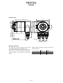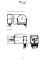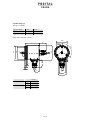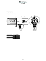
1
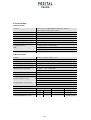
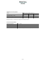
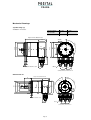
ABSOLUTE ROTARY ENCO DER W ITH DEVICE NET INTERFACE
USER MANUAL
Page1
CONTENTS
Imprint
FRABA POSITAL GmbH
Disclaimer of Warranty
FRABA
POSITAL
GmbH
Schanzenstraße 35
D-51063 Köln
representations or warranties, either express or
implied, by or with respect to anything in this
Telefon
Telefax
manual. And shall not be liable for any implied
warranties of merchantability and fitness for a
Internet
e-mail
+49 (0) 221 96213-0
+49 (0) 221 96213-20
http://www.posital.com
[email protected]
makes
no
particular purpose or for any indirect, special, or
consequential damages.
Copyright
Document information
The company FRABA POSITAL GmbH claims
copyright on this documentation. It is not allowed
File name: UME-OCD-D.doc
Date:
07/05
to modify, extend, copy, or hand over to a third
party this documentation without written
Version number: 1.2
Author: KMA/EIO
approval by the company FRABA POSITAL
GmbH .Nor is any liability assumed for damages
Phone Service
resulting from the use of the information
contained herein. Further, this publication and
For
technical
support,
questions
and
suggestions for improving our products and
features described herein are subject to change
without notice.
documentations call our telephone line +49 (0)
221-96213-0.
Alteration of Specifications reserved
Technical specifications, which are described in
this manual, are subject to change due to our
permanent strive to improve our products.
Page 2
1. Introduction ..................................................... 4
1.1 Control and Information Protocol (CIP) ............5
Clamp flange (C10) ..............................................37
Clamp flanch (S), 5 pin connector ........................38
1.2 Object modell ...................................................6
Hollow Shaft (B) ...................................................39
2. Data Transmission.......................................... 7
Mounting instructions hollow shaft.................39
2.1. The Object Dictionary .....................................7
2.2 Definition of the CAN-ID...................................8
Heavy Duty version ...........................................40
Main features .......................................................40
3. Programmable Parameters ............................ 9
3.1. Encoder parameters .......................................9
Heavy Duty version with blind shaft .....................41
10. Versions / Order Description......................42
3.1.2. Resolution per revolution .............................9
3.1.5. MAC-ID ......................................................11
3.1.6. Baudrate ....................................................11
4. Operating Mode............................................. 12
4.1. Polled Mode ..................................................12
4.2. Change of State Mode ..................................14
4.3. Saving Parameter .........................................16
5. Transmission of the actual position............ 16
6. Installation ..................................................... 17
6.1. Electrical connection .....................................17
6.2. Setting of the baudrate..................................18
6.3 Cabel .............................................................18
6.3 Connector ......................................................18
7. Power On ....................................................... 19
7.1. Operating Mode ............................................19
7.2. Programming ................................................19
7.2.1. Operating Parameter .................................19
7.2.3. Total resolution ..........................................20
7.2.4. Preset Value ..............................................21
7.2.5. MAC-ID ......................................................22
7.2.6. Baudrate ....................................................22
8. RsNetworx ..................................................... 24
8.1. EDS Wizard ..................................................24
8.2 Driver Configuration .......................................26
8.3 Network Connection.......................................28
9. Technical Data............................................... 31
9.1 Electrical Data................................................31
9.2 Mechanical Data ............................................31
9.3 Minimum (mechanical) lifetime.......................32
9. 4 Environmental Conditions .............................32
Mechanical Drawings ....................................... 33
Synchro flange (S) ............................................ 36
Page3
1. Introduction
Absolute rotary encoders provide a definite value
for every possible position. All these values are
The integrated CAN-Bus interface of the absolute
rotary encoder supports all of the DeviceNet
reflected on one or more code discs. The beams of
infrared LEDs are sent through code discs and
functions. The following modes
programmed and enabled or disabled:
detected by Opto-Arrays. The output signals are
electronically amplified and the resulting value is
-
transferred to the interface.
The protocol supports the programming of the
following additional functions:
The absolute rotary encoder has a maximum
resolution of 65536 steps per revolution (16 Bit).
Code sequence (Complement)
Resolution per revolution
The Multi-Turn version can detect up to 16384
revolutions (14 Bit). Therefore the largest resulting
Total resolution
Preset value
resolution is 30 Bit = 1.073.741.824 steps. The
standard Single-Turn version has 12 Bit, the
Baudrate
MAC-ID
can
be
Polled Mode
Change of State
standard Multi-Turn version 24 Bit.
The general use of absolute rotary encoders with
DeviceNet interface is guaranteed.
Page 4
1.1 Control and Information Protocol (CIP)
The DeviceNet specification defines the
Application Layer and the Physical Layer. The
CIP (Common Industrial Protocol) make for the
user available four essential functions:
Data Link layer is based on the CANspecification. For the optimal industrial control
•
Unique control service
will be defined two different messaging types.
I/O messaging (Implicit Messaging ) and explicit
•
•
Unique communication service
Unique allocation of messaging
messaging.With Implicit Messaging becoming
I/O data exchanged in realtime and with Explicit
•
Common knowledge base
Messaging becoming
configure a device.
data
exchanged
to
Page5
1.2 Object modell
DeviceNet describes all data and functions of a device considering as object model. By means of that
object-oriented description a device can be defined complete with single objects. A object is defined across
the centralization by associated attributes (e.g. processdata), his functions (read- or write access of a
single attribute) as well as by the defined behaviour.
DeviceNet distinction is drawn between three different objects:
•
Communication object
Define the exchange messages over DeviceNet and becoming designated as Connection
Objects. (DeviceNet Object, Message Router Object, Connection Object, Acknowledge Handler
Object)
•
System objects
Define common DeviceNet-specific data and functions. (Identity Object, Parameter Object)
•
Applications-specific objects
Define device-specific data and functions. (Application Object, Assembly Object)
Page 6
2. Data Transmission
The data transmission in the DeviceNet network
is realised by message telegrams. Basically,
CAN-ID
Message Header
Message Body
11 Bit
1 Byte
7 Byte
these telegrams can be divided into the CAN-ID
and 8 following bytes as shown in the table
below:
2.1. The Object Dictionary
Instance Attribute of the Position Sensor Objects
Class Code:
23 hex
Attribute
ID
Access
Name
Data Type
Description
1 hex
Get
Number of Attributes
USINT
Number of supported Attributes
2 hex
Get
Attribute
Array of USINT
List of supported Attribute
3 hex
Get
Position value
DINT
current position
0B hex
Get / Set Code sequence
Boolean
Controls the code sequence
clockwise or counterclockwise
2C hex
Get / Set resolution per revolution
INT
resolution for one revolution
2D hex
Get / Set total resolution
DINT
total measurable resolution
2E hex
Get / Set preset value
DINT
setting a defined position value
6E hex
Get / Set Baudrate
Adjustment of the Baudrate
6F hex
Get / Set MAC ID
Adjustment of the MAC ID
Get / Set:
: read, write
Page 7
2.2 Definition of the CAN-ID
DeviceNet is based on the standard CAN-
CAN-Identifier consists of the Message Group,
protocol and used a 11Bit (2048 specifiable
messages) messages identifier. For the
Message ID and the MAC ID of the device.
By our absolute rotary encoder it is a matter of a
identification of a device in a DeviceNet network
are 6Bit enough because a network belongs 64
Group 2 Messages. In the table below a user
can see the importance CAN-IDs for a certain
nodes. That nodes will be call MAC-ID. The
.
communication type.
10 9
0
8
7
6
Group 1
5
4
3
2
1
0
Identity
Hex
Usage
Range
Source MAC ID
GROUP 1 Message
000-3ff
Message ID
0
1
1
0
1
Source MAC ID
Slave’s I/O Change of State or Cyclic Message
0
1
1
1
1
Source MAC ID
Slave’s I/O Poll Response or Change of State/Cyclic
1
0
MAC ID
Acknowledge Message
Group 2
GROUP 2 Messages
Message
ID
1
0
Destination
ID
MAC 0
1
0
Master’s Change of State or Cyclic Acknowledge
Message
1
0
Source MAC ID
0
1
1
Slave’s Explicit/Unconnected Response Messages
1
0
Destination
ID
MAC 1
0
0
Master’s Explicit Request Message
1
0
Destination
ID
MAC 1
0
1
Master’s I/O Poll Command/Change of State/Cyclic
Message
1
0
Destination
MAC 1
1
0
Group 2 Only Unconnected Explicit Request Message
1
0
MAC 1
1
1
ID
Destination
(reserved)
Duplicate MAC ID Check Messages
ID
Page 8
400 - 5ff
3. Programmable Parameters
3.1. Encoder parameters
3.1.1. Operating Parameter
The operating parameter can be used to select the
code sequence.
Attribute ID
Default value
Value range
Data Type
0 b hex
1 hex
0 hex - 1hex
Boolean
The parameter code sequence (complement)
defines the counting direction of the process value
Bit 0
Drehrichtung
Ausgabecode
as seen on the shaft whether clockwise or
counter clockwise.
The counting direction is
1
CW
Steigend
0
CCW
Fallend
defined in the attribute 0b hex:
3.1.2. Resolution per revolution
The parameter resolution per revolution is used to
steps per revolution. Each value between 1 and
program the encoder to set a desired number of
the maximum (see type shield) can be realised
Attribute ID
Default value
Value range
Data Type
2C hex
(*)
0hex - 2000hex
Unsigned Integer16
(*) see type shield, Maximum resolution:
12/24 Bit Encoder: 1,000 hex (4096)
13/25 Bit Encoder: 2,000 hex (8192)
When the value is set larger than 4096 (8192 for a
13/25 Bit encoder), the process value of the
be skipped while rotating the shaft. So, it is
recommended, to keep the measuring steps per
encoder will not be single stepped and values will
revolution below 4096 (8192) measuring steps.
Page 9
3.1.3. Total resolution
This value is used to program the desired number
(25 bit = 33,554,432 steps). Please note the value
of measuring steps over the total measuring range.
This value must not exceed the total resolution of
written on the type shield.
the encoder with 24 bit = 16,777,216 steps
Attribute ID
Default value
Value range
Data Type
2D hex
(*)
0h - 2,000,000h
Unsigned Integer 32
(*) see type shield
Maximum total resolution
24 Bit Encoder: 1,000,000 hex
25 Bit Encoder: 2,000,000 hex
Attention:
Total resolution
The following formula letters will be used:
PGA Physical total resolution of the encoder
GA = PGA * AU / PAU, if AU < PAU
Example: Customer requirement: AU = 2048,
PAU
(see type shield)
Physical resolution per revolution (see
-
GA
type shield)
Total resolution (customer parameter)
-
AU
-
Encoder type shield: PGA=24 bit, PAU=12 bit
GA = 16777216 * 2048 / 4096
GA = 8388608
Resolution per revolution (customer
parameter)
If the total resolution of the encoder is less than the
physical total resolution, the parameter total
If the desired resolution per revolution is less than
resolution must be a multiple of the physical total
resolution:
the physical resolution per revolution of the
encoder, then the total resolution must be entered
as follows:
-
k = PGA / GA
k = integer
3.1.4. Preset value
The preset value is the desired position value,
encoder is set to the desired process value by
which should be reached at a certain physical
position of the axis. The position value of the
the parameter preset. The preset value must not
exceed the parameter total measuring units
Attribute ID
Default value
Value range
Data Type
2E hex
0 hex
0hex - total measuring range
Unsigned Integer 32
Page 10
3.1.5. MAC-ID
Attribute ID
Default value
Value range
Data length
6F hex
0 hex
0hex – 3Fhex
BYTE
Each node in a Device Net network is identified
using a MAC-ID (Media Access Control
64 nedoes. The MAC-ID can only be adjusted
via explicit messaging. The default MAC-ID is
Identifier). Every device needs an explicit and
unique MAC-ID. A Device Net netwok supports
setting on d63.
3.1.6. Baudrate
Attribute ID
Default value
Value range
Data length
6E hex
0 hex
0hex - 2hex
BYTE
Device Net supports three different baurates that
baudrate has to be the same as the Device Net
are being showed in the below table. The
baudrate can be changed via explicit messages
network baudrate. The default baudrate is
setting 125kBaud.
and stored in the EEPROM with a save
command. It is to insure that the selective
0x
Baudrate in kBaud
0
125
1
250
2
500
Page11
4. Operating Mode
4.1. Polled Mode
For switching the polled mode on the following
following example a master MAC ID of 0A hex and
telegrams are needed. Further it is assumed in the
a slave MAC ID of 03 hex.
Allocate Master / Slave Connection Set
1. Allocate Polling
Byte Offset
Bit 7
Bit 6
Bit 5
0
Frag [0]
XID
MAC ID
Bit 4
1
R/R [0]
Service [4B]
Bit 3
Bit 2
Bit 1
Bit 0
Class ID [03]
Instance ID [01]
Allocation Choice [03]
0
0
Allocator MAC ID
Definition CAN ID
10
9 8 7 6 5 4 3 2 1 0 Identity
Usage
1
0 Destination MAC 1 1 0 Group 2 Only Unconnected
ID
Message (reserved)
Example:
CAN-ID
41E
Hex
Range
Explicit
Request
Byte 0
Byte 1
Byte 2
Byte 3
Byte 4
Byte 5
0A
4B
03
01
03
0A
1. Setting the Expected_packet_rate of the Explicit Message Connection on 0:
Definition CAN-ID
10
9 8 7 6 5 4 3 2 1 0 Identity
Usage
Hex
Range
1
0 Destination MAC 1 0 0 Master´s Explicit Request Message
ID
Page12
Example:
CAN-ID
41C
Byte 0
Byte 1
Byte 2
Byte 3
Byte 4
Byte 5
Byte 6
0A
10
05
01
09
00
00
1. Setting the Expected_packet_rate of the Polling Connection on 0:n:
Example:
CAN-ID
41C
Byte 0
Byte 1
Byte 2
Byte 3
Byte 4
Byte 5
Byte 6
0A
10
05
02
09
00
00
Release Master / Slave Connection Set
Release Polling
Byte Offset
Bit 7
Bit 6
Bit 5
0
Frag [0]
XID
MAC ID
1
R/R [0]
Service [4C]
Bit 4
Bit 3
Bit 2
Bit 1
Bit 0
Class ID [03]
Instance ID [01]
Release Choice [03]
Example:
CAN-ID
Byte 0
Byte 1
Byte 2
Byte 3
Byte 4
41E
0A
4C
03
01
03
Page 13
4.2. Change of State Mode
The absolute rotary encoder sends data, without
any request from the host, when the actual
when the position value is not changing. This
results in a reduced bus loading.
process value is changing. No telegram will occur
Allocate Master / Slave Connection Set
Allocate COS
Byte Offset
Bit 7
Bit 6
Bit 5
0
Frag [0]
XID
MAC ID
Bit 4
1
R/R [0]
Service [4B]
Bit 3
Bit 2
Bit 1
Bit 0
Class ID [03]
Instance ID [01]
Allocation Choice [51]
0
0
Allocator MAC ID
Example:
CAN-ID
Byte 0
Byte 1
Byte 2
Byte 3
Byte 4
Byte 5
41E
0A
4B
03
01
51
0A
2. Setting Expected_packet_rate of the Explicit Message Connection on 0:
Example:
CAN-ID
Byte 0
Byte 1
Byte 2
Byte 3
Byte 4
Byte 5
Byte 6
41C
0A
10
05
01
09
00
00
3.
Setting Expected_packet_rate of the Change of State Connection on 0:
Example:
CAN-ID
41C
Byte 0
Byte 1
Byte 2
Byte 3
Byte 4
Byte 5
Byte 6
0A
10
05
04
09
00
00
Page 14
Release Master / Slave Connection Set
Release COS
Byte Offset Bit 7
Bit 6
Bit 5
0
Frag [0]
XID
MAC ID
1
R/R [0]
Service [4C]
Bit 4
Bit 3
Bit 2
Bit 1
Bit 0
Class ID [03]
Instance ID [01]
Release Choice [51]
Example:
CAN-ID
41E
Byte 0
Byte 1
Byte 2
Byte 3
Byte 4
0A
4C
03
01
51
Page 15
4.3. Saving Parameter
The parameters of the absolute rotary encoder are
examination, those values can be saved in the
saved in a non-volatile FLASH memory. Because
of a limited number of writing cycles (≈ 1,000), it is
FLASH memory. After successful saving of the
parameter the encoder sends his MAC-ID on the
useful to transmit the modified parameter in the
first step only in the RAM area. After adjusting and
bus. To get the process value a new allocation of
the slave is required.
Byte
Offset
Bit 7
Bit 6
Bit 5
Bit 4
0
Frag [0]
XID
MAC ID
1
R/R [0]
Service [32]
Bit 3
Bit 2
Bit 1
Bit 0
Class ID [23]
Instance ID [01]
Example:
(MAC-ID Master: 0A hex, MAC-ID Slave: 03 hex)
CAN-ID Byte 0 Byte 1
Byte 2
Byte 3
41C
0A
32
23
01
5. Transmission of the actual position
The process value is transmitted according to the
following table.
CAN-ID
process value
11 Bit
Byte 0
7
2 to 2
Byte 1
0
2
15
to 2
Byte 2
8
Page 16
2
23
to 2
Byte 3
16
2
31
to 2
24
6. Installation
6.1. Electrical connection
The rotary encoder is connected by three cables.
There is a resistor provided in the connection cap,
The power supply is achieved with a two-wire
connection cable through one PG 9. Each one of
which must be used as a line termination on the
last device
the twisted-pair and shielded bus lines are guided
in and out through two PG 9 on the right side (as
Resistor:
seen on clamps)
Last Device
Device X
RT
RT
ON
ON
RT
ON
The setting of the node number is achieved by 2
G L
901
L
H
901
23
23
23
78
901
H G
78
-
78
+
456
456
456
Bd
x10
x1
turn-switches in the connection cap. Possible
addresses lie between 0 and 63 whereby every
address can only be used once. 2 LEDs on the
backside of the connection cap show the operating
DeviceNet Devices
BCD coded rotary switches
x1
Device adress 0...63
Setting CAN-node number
x10
xBd Setting of the baud-rate
status of the encoder.
Clamp
Description
⊥
+
-
Ground
CG
CAN Ground
CL
CAN Low
CH
CAN High
CG
CAN Ground
CL
CAN Low
CH
CAN High
24 V Supply voltage
0 V Supply voltage
Page 17
6.2. Setting of the baudrate
Baudrate in kBit/s
BCD coded rotary switches
125
0
250
1
500
2
125
3
reserved
4...9
6.3 Cabel
Pin
Signal
Description
Color
1
V-
GND
Black
2
CAN-L
CAN Bus signal (dominant low)
Blue
3
CAN-H
CAN Bus signal (dominant high)
White
4
V+
External voltage supply Vcc
Red
6.3 Connector
Pin
Signal
Description
Color
2
V+
External voltage supply Vcc
Red
3
V-
GND
Black
4
CAN-H
CAN Bus signal (dominant high)
White
5
CAN-L
CAN Bus signal (dominant low)
Blue
4
3
5
1
2
5 pin connector
Page 18
7. Power On
7.1. Operating Mode
After power on the absolute rotary encoder sends
two times his MAC ID telegram on the bus.
7.2. Programming
If some parameters should not be modified you
format. In the examples, the CAN ID and MAC ID
can skip over this chapter.
are 0A (hex) and for the slave 03 (hex).
The following numbers are given in hexadecimal
The changeable values are written in an italics.
7.2.1. Operating Parameter
Master to absolute rotary encoder:
Set-Parameter
CAN ID
MAC ID
Service
Class
Instance
Code
ID
ID
ID
Byte 0
Byte1
Byte 2
Byte 3
Byte 4
0A
10
23
01
0b
41C
X:
Attribute
Data
Byte 5 Byte 6
X
-
Byte 7
-
1 hex for CW (Default)
0 hex for CCW
Absolute Rotary Encoder to Master:
CAN ID
Confirmation
MAC ID
Service Code
Byte 0
Byte 1
0A
90
41B
7.2.2. Resolution per revolution
Master to Absolute Rotary Encoder: Set-Parameter
CAN ID
41C
X:
MAC ID
Service
Class
Instance Attribute
Code
ID
ID
ID
Byte 0
Byte 1
Byte 2
Byte 3
Byte 4
Byte 5
Byte 6
0A
10
23
01
2C
X
X
desired resolution per revolution
Page 19
Data
Byte 7
-
Absolute rotary encoder to master:
CAN ID
41B
Confirmation
MAC ID
Service Code
Byte0
Byte1
0A
90
7.2.3. Total resolution
A fragmented transmission is needed, when the
total resolution must be sent to the encoder.
So here are more messages necessary.
Master to Absolute Rotary Encoder: Set-Parameter
CAN ID
41C
MAC ID
Fragment
41B
Class
Instance
Attribute
Code
ID
ID
ID
Byte 0
Byte 1
Byte 2
Byte 3
Byte 4
Byte 5
Byte 6
Byte 7
8A
00
10
23
01
2D
X
X
Absolute Rotary Encoder to Master:
CAN ID
Service
Confirmation
MAC ID
Byte0
Byte 1
Byte 2
8A
C0
00
Master to Absolute Rotary Encoder: Set-Parameter
CAN ID
MAC ID
Fragment
Byte 0
Byte 1
41C
8A
81
X: desired total resolution
Byte 2
Byte 3
Byte 4
Byte 5
Byte 6
Byte 7
X
X
-
-
-
-
Absolute Rotary Encoder to Master:
CAN ID
41B
Byte0
Byte 1
Byte 2
8A
C1
00
Absolute Rotary Encoder to Master:
CAN ID
41B
Confirmation
MAC ID
Confirmation
MAC ID
Service Code
Byte0
Byte1
0A
90
Page 20
7.2.4. Preset Value
Master to Absolute Rotary Encoder: Set-Parameter
CAN ID
41C
MAC ID
Fragment
Service
Class
Instance
Attribute
Code
ID
ID
ID
Byte 0
Byte 1
Byte 2
Byte 3
Byte 4
Byte 5
Byte 6
Byte 7
8A
00
10
23
01
2E
X
X
X: desired preset value
Absolute Rotary Encoder to Master
CAN ID
41B
Confirmation
MAC ID
Byte0
Byte 1
Byte 2
8A
C0
00
Master to Absolute Rotary Encoder: Set-Parameter
CAN ID
41C
MAC ID
Fragment
Byte 0
Byte 1
Byte 2
Byte 3
Byte 4
Byte 5
Byte 6
Byte 7
8A
81
X
X
-
-
-
-
X: desired preset value
Absolute Rotary Encoder to Master
CAN ID
41B
Byte0
Byte 1
Byte 2
8A
C1
00
Absolute Rotary Encoder to Master:
CAN ID
41B
Confirmation
MAC ID
Confirmation
MAC ID
Service Code
Byte0
Byte1
0A
90
Page 21
7.2.5. MAC-ID
Master to encoder:
CAN ID
41C
Set-Parameter
MAC ID
Service
Class
Instance Attribute
Code
ID
ID
ID
Data
Byte0
Byte1
Byte 2
Byte 3
Byte 4
Byte 5
Byte 6
Byte 7
0A
10
23
01
6F
X
-
-
Data
X:Value of the MAC-ID
Encoder to Master:
CAN ID
41B
Confirmation
MAC ID
Service Code
Byte0
Byte1
0A
90
7.2.6. Baudrate
Master to encoder:
CAN ID
41C
Set-Parameter
MAC ID
Service
Class
Instance
Attribute
Code
ID
ID
ID
Byte0
Byte1
Byte 2
Byte 3
Byte 4
Byte 5
Byte 6
Byte 7
0A
10
23
01
6E
X
-
-
X: Value of the Baudrate
X
Baudrate
o
125kbaud
1
250kbaud
2
500kbaud
Encoder to Master:
CAN ID
41B
Confirmation
MAC ID
Service Code
Byte0
Byte1
0A
90
Page 22
7.2.7. Parameter Saving
Master to Absolute Rotary Encoder:
CAN ID
Set-Parameter
MAC ID
Service Code
Class ID
Instance ID
Byte0
Byte1
Byte 2
Byte 3
32
23
01
If the transfer has been successful, the absolute
If the transfer is not successful, an error
rotary encoder responds after 3-4s with the
message will be sent. The service code used to
Duplicate MAC-ID. After that the master must
save the parameter set is manufacturer specific.
reallocate the slave.
Page 23
8. RsNetworx
8.1. EDS Wizard
The EDS File contains information about device
which can be used to configure the device in the
specific
network, for example with RsNetworx from
parameters
as
well
as
possible
operating modes of the encoder. With this file
Rockwell.
you have a data sheet in an electronic format,
1.1 EDS Wizard
be chosen and after that the button weiter. In the
To install the EDS file the EDS Wizard has to be
started, that can be done in the menu Tools/EDS
Wizard.
If
the
EDS
Wizard
is
next step the Register a directory of EDS files
activated
has to be chosen and with Browse the path of
successfully the Register an EDS File(s) has to
the EDS file(s). That is indicated in picture 1.2.
Page 24
1.2 EDS Wizard
The Wizard finds all EDS files that are discarded
(see picture 1.3) pictures can be selected for the
using
check the EDS files on errors. In the next step
installation can be continued and finished.
Page 25
nodes. With
the
button
the
in the choosing path and operates a test to
weiter
1.3 EDS Wizard
8.2 Driver Configuration
After a successful installing of the EDS file the
KFD is being used. In the next step the window
next step is to choose the suitable driver. With
Start/Programme/Rockwell Software/RSLinx in
Configure Drivers in the menu Communications/
Configure Drivers has to be started. In the drop
the menu the programm RSLinx can be started.
down Menü Available Driver Types the driver typ
With this programm the suitable driver can be
1770-KFD has to be chosen and confirmed with
chosen. For this example the driver typ 1770-
the button Add New. (See picture 1.4)
Page 26
1.4 Cofigure Drivers
If the suitable driver is chosen it can be
registered (picture 1.5). In the next step a
configured in the window Driver Configuration. In
requested
this step the correct baudrate has to be
1.5 Driver Configuration
Page 27
name
can
be
registered.
8.3 Network Connection
This chapter will explain how to switch a network
has been choosen, this is explained in chapter
online and how to parametrise a encoder. In the
6.2, the network is online. After that RsNetworx
menu Network/ Online the window Browse for
searches in the network for connecting nodes.
network will be opened. If the driver 1770-KFD
That is also being showed in picture 1.6.
1.6 Browsing Network
To cofigure the encoder the configuration
opened. By pushing Parameters an upload of
window in the menu Device/Properties has to be
the encoder parameter is realized.
Page 28
1.7 Upload Parameter
After a successful upload of the parameters,
pushed.
those can be configured as the picture 1.8 below
configuration parameters are not stored in the
shows.
A
download
of
the
It
should
be
noticed
that
the
configured
EEPROM. To store the parameters in the
parameters can be realized with the yellow
EEPROM the window in the menu Device/Class
arrow that is showing down and is placed at the
top right in the configuration window. An upload
Instance Editor has to be opened. The entries
that are necessary to store the parameters are
can be realized with the arrow beside the
being showed in the picture 1.9 below. At last
download arrow which is showing up. To show
the button execute has to be executed to store
the position value the button Monitor has to be
the parameters in the EEPROM.
Page 29
1.8 Configure Parameters
1.9 Service Class Instance Attribute Editor
Page 30
9. Technical Data
9.1 Electrical Data
Interface
Transceiver according ISO/DIS 11898, up to 64 nodes
galvanically isolated by opto-couplers
Transmission rate
150 kBaud, 250 kBaud, 500kBaud
Device addressing
Adjustable by rotary switches in connection cap
Supply voltage
10 - 30 V DC (absolute limits)
Current consumption
max. 230 mA with 10 V DC, max. 100 mA with 24 V DC
Power consumption
max. 2.5 Watts
Step frequency LSB
800 kHz
Accuracy of division
± ½ LSB (12 bit), ± 2 LSB (16 bit)
EMC
Emitted interference: EN 61000-6-4
Noise immunity:
Electrical lifetime
EN 61000-6-2
5
> 10 h
9.2 Mechanical Data
Housing
Aluminum, optional stainless steel
Lifetime
Dependent on shaft version and shaft loading – refer to table
Max. shaft loading
Axial 40 N, radial 110 N
Inertia of rotor
≤ 30 gcm
Friction torque
≤ 3 Ncm (without shaft sealing)
RPM (continuous operation)
Singleturn:
max. 12,000 RPM
Multiturn:
max. 6,000 RPM
2
Shock (EN 60068-2-27)
≤ 30 g (halfsine, 11 ms)
Permanent shock (EN 60028-2-29)
≤ 10 g (halfsine, 16 ms)
Vibration (EN 60068-2-6)
≤ 10 g (10 Hz ... 1,000 Hz)
Weight (standard version)
Singleturn:
≈ 550 g
Multiturn:
≈ 600 g
Singleturn:
≈ 1,100 g
Multiturn:
≈ 1,200 g
Weight (stainless steel version)
Flange
Synchro (S)
Clamp (C)
Hollow shaft (B)
Shaft diameter
6 mm
10 mm
10 mm
15 mm
Shaft length
10 mm
20mm
20 mm
-
-
-
-
15 mm / 30 mm
hollow shaft depth min. / max.
Page 31
9.3 Minimum (mechanical) lifetime
8
Flange
Lifetime in 10 revolutions with Fa / Fr
40 N / 60 N
40 N / 80 N
40 N / 110 N
C10 (Clamp flange 10 x 20)
247
104
40
S10 (Synchro flange 10 x 20)
262
110
42
S6 (Synchro flange 6 x 10) without shaft sealing
822
347
133
S6 (Synchro flange 6 x 10) with shaft sealing: max. 20 N axial, 80 N radial
9. 4 Environmental Conditions
Operating temperature
– 40 .. +85°C
Storage temperature
- 40 .. + 85 °C
Humidity
98 % (without liquid state)
Protection class (EN 60529)
Casing side: IP 65
Shaft side: IP 64 (optional with shaft sealing: IP66)
Page 32
Mechanical Drawings
Synchro flange (S)
available in 2 versions
Synchro flange
d / mm
l / mm
Version S06
6f6
10
Version S10
10h8
20
Single-Turn=82, Multi-Turn=92
30
3xM4x6
Ø42
Ø60
~32
l
63,5
Ø59 (Ø61)*
d
ø58
ø50 f7
0°
12
3x
23
3
3
4
* Edelstahl / Stainless steel
15
Ø6,5-9
20
20
Schlüsselweite, wrench size=17
Clamp flange (C)
Single-Turn=82, Multi-Turn=92
30
30
3xM4x6
0°
12
3x
3xM3x6
Ø4
8
15°
Ø60
23
63,5
3
~27
Ø36 f7
Ø10 h8
Ø53
Ø58
1
Ø59 (Ø61)*
18
3x12
0°
10
3
* Edelstahl / Stainless steel
15
Ø6,5-9
20
20
Schlüsselweite, wrench size=17
Page 33
Hollow shaft (B)
72
Ø63
Single-Turn=100 , Multi-Turn=112
3,3
20
Ø60
63,5
Ø15 F7
23
20°
Ø59 (Ø61)*
1,3
* Edelstahl / Stainless steel
Max. W ** = 30
Min. W ** = 15
~32
Anlagekante
an Momentenstütze
(lay-on edge
torque support)
Ø3,2
Ø6,5-9
15
20
** Welleneinstecktiefe (hollow shaft depth)
20
Schlüsselweite, wrench size=17
Mounting instructions
The clamp ring may only be tightened if the shaft
Allowed shaft movements of the drive element are
of the driving element is in the hollow shaft.
listed in the table.
The diameter of the hollow shaft can be reduced to
axial
radial
reducing adapter can be pushed into the hollow
static
± 0,3 mm
± 0,5 mm
shaft).
dynamic
± 0,1 mm
± 0,2 mm
12mm, 10 mm or 8 mm by using an adapter (this
Page 34
Connection cap with 5pin round connector, Micro style
20
66
23
Ø60
30
15
12
Square flange (Q)
Single-Turn=89, Multi-Turn=115
52,4
4x Ø5
29,2
23
R5
~32
9.52 +0
-0.013
1
+0.050
Ø31.75+0.025
66,5
7,6
19,0
Ø47,6
Ø47,6/3x10-32UNF-2B; 4,6tief
30
3x
12
0°
6,3
15
Page 35
20
20
Synchro flange (S)
Two types available
Synchro flange
d / mm
l / mm
Typ S06
6f6
10
Typ S10
10h8
20
Cable (cable diameter = 8 mm )
Ø42
L
~28
3xM4x6
Ø59
d
Ø50f7
Ø58
20°
3x1
5
l
~33
3
3
4
~18
25
30
L in mm
Single-Turn
Multi-Turn
axial
53
radial
53
axial
62
radial
62
Seite 36
Clamp flange (C10)
Cable (cable diameter = 8 mm )
~28
L
3xM4x6
Ø4
8
3x12
0°
5
15°
Ø59
Ø10 h8
Ø36 f7
Ø53
Ø58
1
18
0°
12
3x
3xM3x6
3
~33
3
25
~18
30
L in mm
Single-Turn
Multi-Turn
axial
53
radial
53
axial
62
radial
62
Page 37
Clamp flanch (S), 5 pin connector
The dimensions of the housing from type Clamp
flange 5 pin connector are the same like the type
synchro flange.
L
3xM4x6
15°
Ø59
Ø4
8
3x12
0°
1
Ø10 h8
Ø36f7
Ø53
Ø58
°
20
18
1
3x
3xM3x6
3
3
L im mm
Single-Turn
Multi-Turn
axial
53
radial
53
axial
62
radial
62
Page 38
Hollow Shaft (B)
72
Ø63
~28
L
3,3
Anlagekante
an Momentenstütze
(lay-on edge
torque support)
Ø59
Ø15 F7
1,3
20°
20
24
Ø3,2
M23x1
25
30
Max. W ** = 30
Min. W ** = 15
** Welleneinstecktiefe (hollow shaft depth)
L
Single-Turn
Multi-Turn
axial
72
radial
72
axial
81
radial
81
Mounting instructions hollow shaft
The clamp ring may only be tightened if the shaft
of the driving element is in the hollow shaft.
The diameter of the hollow shaft can be reduced
to 12mm, 10 mm or 8 mm by using an adapter
(this reducing adapter can be pushed into the
hollow shaft).
Allowed shaft movements of the drive element
are listed in the table.
Page 39
axial
radial
static
± 0.3 mm
± 0.5 mm
dynamic
± 0.1 mm
± 0.2 mm
Heavy Duty version
industrial environment e.g. heavy construction
Main features
- Compact dimensions
machines. The heavy duty option for the Pure
- Heavy Duty housing
CANopen
- Protective element against perspiration water
These „Outdoor encoder“ are suitable for dirty
encoder
provides
an
extended
temperature range, protection elements against
- integrated T-coupler
perspiration water inside the encoder and a
- Standard protection class:
heavy duty housing. Uppermost attention was
IP66 shaft side
laid on a high EMI. Micro style connectors for
IP67 casing side
supply voltage and bus-in / bus-out connection
provide an easy installation for non professional
people.
The
parametrization
of
the
Pure
CANopen encoder is possible with all current
project tools by implementation of the ESD file to
the current project.
Page 40
Heavy Duty version with full shaft
Flangetype
l [mm]
Clampflange available in two versions.
Standard
10
Optional
4
M4x6
Singleturn=45, Multiturn=69
Ø48
73
Ø60
Ø10 h8
ø58
Ø36 f7
0°
12
3x
17,5
l
12,5
32
21,5
IN
OUT
55
Heavy Duty version with blind shaft
Allowed shaft movement of drive element
is listed in the table.
Axial
Radial
static
± 0,3 mm
± 0,5 mm
dynamic
± 0,1 mm
± 0,2 mm
72
Singleturn=66, Multiturn=90
Ø63
3,3
73
20
Ø60
20°
Ø12 F7
1,3
Anlagekante
an Momentenstütze
Ø3.2
12,5
32
21,5
IN
Max. Welleneinstecktiefe = 30
Min. Welleneinstecktiefe = 15
Page 41
OUT
10. Versions / Order Description
Description
Type Key
Optocode
OCDDeviceNet
Interface
D2
B1
B-
__
_ _-
__
_-
0CC
D2
B1
Version
Code
Binary
Revolutions (Bits)
Singleturn
B
Multiturn (4096 revolutions)
00
12
Multiturn (16384 revolutions)
14
Steps per revolution
4096
12
(Bits)
13
16
Flange
8192
65536
Clamp flange
Shaft diameter
Synchro flange
Hollow shaft
Square flange
10 mm
Mechanical options
06 mm
15 mm (hollow shaft)
Without
Connection
_
C
S
B
Q
10
06
15
0
Shaft sealing (IP66)
S
Stainless steel version
V
Heavy Duty
H
Customized
C
0CC
Connection Cap
Has to be ordered separately – see accessories
Connector, 5-pin, M12, radial
Connector, 5-pin, M12, axial
Cable ; radial (1m)
Cable ; axial (1m)
Heavy Duty
Standard = bold, further models on request
Page 42
PRM
PAM
CRW
CAW
PRN
Connection caps
Description
Type
Standard
T-coupling-functionality
DeviceNet
setting
with
integrated
address AH 58-B1DA-3PG
Stainless steel configuration
AH 58-B1DA-3PG-VA
Connection with 5pin round connector, Micro style AH 58-B1DA-1BW
M12
Alternative version
2 cable glands for cable diameter: 9 - 13 mm
AH 58-B1DA-2M20
DeviceNet
Accessories and Documentation
Description
Shaft coupling**
Type
Drilling: 10 mm
GS 10
Drilling:: 6 mm
GS 06
Clamp disc**
4 pcs. / AWC
SP 15
Clamp ring**
2 pcs. / AWC
SP H
Reducing adapter ***
15 mm to 12 mm
RR12
Reducing adapter ***
15 mm to 10 mm
RR10
Reducing adapter ***
15 mm to 8 mm
RR8
User Manual*
Installation and configuration manual, German
UMD-DA
User Manual*
Installation and configuration manual, English
UME-DA
EDS-File*
Disc containing EDS-file for coniguration(for OCC).
OCD-DN-C
EDS-File*
Disc containing EDS-file for coniguration.
OCD-DN-0
*** only for hollow shaft
**
needless for hollow shaft
*
These can be downloaded free of charge from our Homepage www.posital.com.
We do not assume responsibility for technical inaccuracies or omissions. Specifications are subject to
change without notice.
Page 43