1
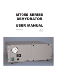
®
ODPMT200 SERIES DryLine
DEHYDRATOR
USER MANUAL
Bulletin AE01B-A0467-001
© 2007 - 2013 CommScope, Inc. All rights reserved
Rev: E
(01/13)
ODPMT200 Series DryLine® Dehydrator User Manual
TABLE OF CONTENTS
Section 1
General Information . . . . . . . . . . . . . . . . . . . . . . . . . . . . . . . . . . . . . . . 3
1.1Introduction . . . . . . . . . . . . . . . . . . . . . . . . . . . . . . . . . . . . . . . . . . . . . . . . . . . 3
1.2Description . . . . . . . . . . . . . . . . . . . . . . . . . . . . . . . . . . . . . . . . . . . . . . . . . . . . 3
1.3Operation . . . . . . . . . . . . . . . . . . . . . . . . . . . . . . . . . . . . . . . . . . . . . . . . . . . . .3
1.4
Triple Alarm Option . . . . . . . . . . . . . . . . . . . . . . . . . . . . . . . . . . . . . . . . . . . . . . 4
Figure 1 - Alarm Label . . . . . . . . . . . . . . . . . . . . . . . . . . . . . . . . . . . . . . . . . . . . 4
Figure 2 - Changing Alarm Outputs: . . . . . . . . . . . . . . . . . . . . . . . . . . . . . . . . . . . 5
1.5
Specifications . . . . . . . . . . . . . . . . . . . . . . . . . . . . . . . . . . . . . . . . . . . . . . . . . .5
Section 2
Installation . . . . . . . . . . . . . . . . . . . . . . . . . . . . . . . . . . . . . . . . . . . . . 6
2.1Inspection . . . . . . . . . . . . . . . . . . . . . . . . . . . . . . . . . . . . . . . . . . . . . . . . . . . . 6
2.2
Controls and Displays . . . . . . . . . . . . . . . . . . . . . . . . . . . . . . . . . . . . . . . . . . . . .6
2.3
Installing the Dehydrator . . . . . . . . . . . . . . . . . . . . . . . . . . . . . . . . . . . . . . . . . . . 7
2.3.1 Slab Mounting . . . . . . . . . . . . . . . . . . . . . . . . . . . . . . . . . . . . . . . . . . . . . . . . . .7
2.4
Power Connections . . . . . . . . . . . . . . . . . . . . . . . . . . . . . . . . . . . . . . . . . . . . . . 7
2.4.1 AC Power . . . . . . . . . . . . . . . . . . . . . . . . . . . . . . . . . . . . . . . . . . . . . . . . . . . . .7
2.5
Connecting the Low Pressure Alarm Output . . . . . . . . . . . . . . . . . . . . . . . . . . . . . .7
2.7
Connecting Dehydrator to the Transmission Line . . . . . . . . . . . . . . . . . . . . . . . . . . .8
2.8 Purging the Transmission Line . . . . . . . . . . . . . . . . . . . . . . . . . . . . . . . . . . . . . . .8
Section 3
Maintenance . . . . . . . . . . . . . . . . . . . . . . . . . . . . . . . . . . . . . . . . . . . . 9
3.1Maintenance . . . . . . . . . . . . . . . . . . . . . . . . . . . . . . . . . . . . . . . . . . . . . . . . . . .9
3.2
Regular Maintenance . . . . . . . . . . . . . . . . . . . . . . . . . . . . . . . . . . . . . . . . . . . . .9
3.3
Preventive Maintenance . . . . . . . . . . . . . . . . . . . . . . . . . . . . . . . . . . . . . . . . . . . 9
3.4
6000 Hour Overhaul . . . . . . . . . . . . . . . . . . . . . . . . . . . . . . . . . . . . . . . . . . . . . 9
3.5
Annual Maintenance . . . . . . . . . . . . . . . . . . . . . . . . . . . . . . . . . . . . . . . . . . . . . 10
3.6
Parts Replacement and Dehydrator Overhaul . . . . . . . . . . . . . . . . . . . . . . . . . . . . 10
3.7
Dehydrator Filter Element Replacement . . . . . . . . . . . . . . . . . . . . . . . . . . . . . . . 11
3.8
Service Restoration . . . . . . . . . . . . . . . . . . . . . . . . . . . . . . . . . . . . . . . . . . . . . 12
Section 4
Troubleshooting . . . . . . . . . . . . . . . . . . . . . . . . . . . . . . . . . . . . . . . . . 13
Figure 3 - Schematic With All Options . . . . . . . . . . . . . . . . . . . . . . . . . . . . . . . . . 14
Figure 4 - Alarm(s) . . . . . . . . . . . . . . . . . . . . . . . . . . . . . . . . . . . . . . . . . . . . . . 15
Section 5
Replacement Parts . . . . . . . . . . . . . . . . . . . . . . . . . . . . . . . . . . . . . . . 16
Section 6
Customer Service . . . . . . . . . . . . . . . . . . . . . . . . . . . . . . . . . . . . . . . . 16
6.1Introduction . . . . . . . . . . . . . . . . . . . . . . . . . . . . . . . . . . . . . . . . . . . . . . . . . . . 16
6.2
In Case of Trouble . . . . . . . . . . . . . . . . . . . . . . . . . . . . . . . . . . . . . . . . . . . . . . 16
6.3
Initial Steps by CommScope . . . . . . . . . . . . . . . . . . . . . . . . . . . . . . . . . . . . . . . 17
6.4
Repair Center Process . . . . . . . . . . . . . . . . . . . . . . . . . . . . . . . . . . . . . . . . . . . 17
6.5
RoHS Inquiries . . . . . . . . . . . . . . . . . . . . . . . . . . . . . . . . . . . . . . . . . . . . . . . . 17
Figure 5 - Hole pattern for locateing J bolts in cement slab. . . . . . . . . . . . . . . . . . . 19
2
ODPMT200 Series DryLine® Dehydrator User Manual
They are designed to mount to a slab floor. Optional brackets are available for pole
mounting capability. Their front panels feature
a pressure gauge, an indicating on/off switch, a
resettable circuit breaker, and a run time meter.
For easy serviceability, power connections,
alarm output connections and all filter elements
are accessible from the front of the unit.
Section 1
General Information
1.1Introduction
This manual contains the information you need
to install, operate and maintain your ODPMT200
Series DryLine™ dehydrator. Please take the
time to read this manual before attempting to
operate or service the unit.
The ODPMT200 maintains transmission line
pressures at 5.0 lb/in2 (34 kPa). It is intended
for standard microwave antenna applications
and any other transmission line pressurization
requirement that supports a relatively high
pressure limit.
1.3Operation
ODPMT200 Theory of operation.
The ODPMT200 series of DryLine™
dehydrators, while similar in moisture removal
technology, operates differently than the rest of
the DryLine™ series of dehydrators. In order to
provide a constant supply of dry air to small air
volume systems, and to maintain an acceptable
moisture level in the product air stream, a highpressure reservoir tank is needed. This reservoir
tank is connected to a pressure regulator and
orifice to yield a fixed output pressure of 5.0 psig
and a nominal flow rate of 0.2 CFM. In addition
to supplying the output air, the reservoir tank
also provides the dry air for the feedback loop.
The feedback loop is necessary to maintain the
dryness of the membrane cartridge.
1.2Description
ODPMT200 Series dehydrators provide dry air
for pressurizing small (up to 40 cubic feet, or
560 liters, in volume) antenna and transmission
line systems. The dehydrators produce -49ºF
(-45ºC) dewpoint dry air at an output rate of 0.2
cubic feet (1.4 liters) per minute.
Each dehydrator consists of an electricallydriven air compressor, a membrane dryer
assembly, an automatic transmission line
pressure sensing system and a low-pressure
alarm output housed in a rigid metal chassis.
During normal operation, the bleed air in the
feedback loop will cause the pressure to drop in
the internal reservoir tank, and the ODPMT200
compressor will cycle automatically. These
cycles will take place regardless of the system
volume or condition of the transmission line the
dehydrator is connected to. The rate of these
cycles, however, will vary. During the purge
cycle, the dehydrator will cycle approximately
every 2 to 4 minutes while showing 0 psig on
the pressure gauge and providing a constant 0.2
SCFM of dry air.
3
When connected to a very tight system, or
the output is capped, the dehydrator will
cycle approximately every 60 to 90 minutes
and maintain 5.0 psig system pressure while
providing close to 0 CFM of dry air. A system
that leaks will have a cycle time somewhere in
between, depending on the severity of the leaks.
ODPMT200 Series DryLine® Dehydrator User Manual
Term.
The pressure gauge will also reflect a pressure
between 0 and 5.0 psig while the output flow
is between 0.2 and 0 SCFM. The pressure
gauge senses pressure beyond the flow control
orifice and will show the actual pressure in the
waveguide.
During the initial pressurization of the
transmission line, the dehydrator will cycle
every 2 to 4 minutes with the system at 0 psig
pressure. As the dehydrator pressurizes the
system, the cycle times will increase until the
dehydrator output is balanced with the system
leak, at which point the cycle times will stabilize.
1.4
1
2
3
4
5
6
7
8
Function
Power Fail Com
Power Fail Alarm
Humidity Com
Humidity Alarm
Excess Run Com
Excess Run Alarm
Low Press. Com.
Low Press. Alarm
Wire Color
Black
Red
Green
Brown
Blue
White
Grey
Orange
Alarm Definitions:
Low Pressure:
If system pressure falls significantly below the
low-pressure trigger point, the low-pressure
alarm sensor will activate an alarm contact.
This alarm is an indication of a significant
system leak or a dehydrator failure.
Triple Alarm Option
This optional assembly is designed to provide
the additional Excess Run, High Humidity and
Power Fail alarms to CommScope Dehydrators.
All alarms are Form C dry contacts and are
factory set for continuity at alarm.
Excess Run:
User settable run time to be set in accordance
with the normal run time for the particular
application. Selectable times are 10, 30, 120
and 240 minutes. See Figure 2 for location of
JP3.
The external alarm monitoring system (not
included) is connected to the terminal strip
located behind the cover. A small slotted
screwdriver is necessary to make the
connections.
Power Fail:
Activates when power is removed from the
dehydrator. This includes turning the power off
at the switch.
The connection to the alarm strip is as follows,
and refer to Figure 1 for correct locations and
colors of the wires on the terminal strip.
High Humidity:
Activates when system or dehydrator output
humidity rise above 7.5% relative humidity.
At initial installation, this alarm will continue
to alarm until the system has been properly
purged.
ALARM
*8*
L.P.
*7*
*6*
X.R.
*5*
*4*
H.H.
*3*
*2*
P.F.
*1*
.5
Figure 1 - Alarm Label
4
ODPMT200 Series DryLine® Dehydrator User Manual
1.5
Figure 2 - Changing Alarm Outputs:
Alarm
Reset
Factory setting
Where To
Low
Normally
Pressure
Closed (N.C.)
Alarm switch
center term.
N.O., bottom
term N.C.
Mains
(Power)
Normally
Open (N.O.)
Alarm PCB
Power Fail
Jumper JP6 on
Excess
Run
Normally
Open (N.O.)
PCB
Jumper JP5 on
Run Alarm
High
Humidity
Normally
Open (N.O.)
Jumper JP4 on
Alarm PCB
Specifications
Output Pressure Constant
5.0 psig
Output capacity
12.0 SCFH (80Iiters/h)
(total, approx.) 0.2
SCFH (1.5 liters/m)
Output Dew Point,
-49°F (-45°C) or better
Operating Temperature
Range
-30° to +130° F
(-34° to +54° C)
Low Pressure Alarm
1.0 lb/in2 (6.9 kPa)
Electrical Input 115 Vac, 50/60 Hz
Output Connector
3/8” polytube,
compression
Dimensions
18.5” W x 32.0” H x
10.0” D
Optional Alarms:
5
High Humidity Alarm
Set Point
7.5% RH, factory set
Excess Run Alarm
Set Point
10 minutes, factory set
Power Fail Alarm
loss of input power
ODPMT200 Series DryLine® Dehydrator User Manual
Section 2
Installation
2.1Inspection
Open carton.
Remove the top piece of corrugated packing.
Carefully remove the installation accessories
and manual and dehydrator. Check the
dehydrator for shipping damage such as dents
or loose parts.
Pressure Gauge - indicates dehydrator output
pressure in psig and kPa.
2.2
ON/OFF Switch - controls compressor and
sensors. Light indicates power switch is ON.
Controls and Displays
Familiarize yourself with the controls and
displays prior to installing or testing the
dehydrator.
To comes from compressor and
connects to the filter bowls.
Circuit Breaker - white tab indicates a circuit
overload. Push to reset.
Dehydrator Controls/Displays
6
ODPMT200 Series DryLine® Dehydrator User Manual
completed, tie-wrap power-cable in place and
tighten the liquid-tite fitting around power cable. See schematic on page 21 for input connections.
Un-Time Meter - provides a visual indication of
the number of hours of compressor operation
and provides validation for the 3000 hour
warranty.
2.3
Installing the Dehydrator
2.3.1
Slab Mounting
Proper electrical connection is
required. It is suggested a licensed
electrician be contracted to connect
the AC wiring to the unit, if it is
connected directly to the mains.
Failure to properly connect the power
wires could result in a dangerous
electrical shock hazard.
See the back of this manual page 21 for a
drawing showing hole placement and overall
size of the unit.
2.4
Power Connections
Test the Dehydrator
Confirm your dehydrator electrical input matches
the available power.
Turn the dehydrator ON and check the output
port inside the front cover to make sure air is
flowing.
Ensure an electrical safety ground
is installed on the ground stud
located adjacent to the power input
connector. (It is intended to be
customer installed in the field to your
halo grounding system.)
115 Vac
ODPMT200-89015
ODPMT200-89315
2.4.1
AC Power
2.5
AC units can be connected into a standard 15
amp power receptacle of the proper voltage.
Make sure the power circuit is properly
grounded.
Verify the power switch is OFF. Feed the power
cable (not supplied) through the liquid-tite
fitting on bottom of unit. Connect power cable
to input terminal strip on unit. Use a small flat
blade screwdriver to tighten connections on
the terminal strip. After power connections are
Connecting the Low Pressure Alarm Output
To connect the low pressure alarm, open the unit
and locate the terminal block (TB-1).
7
ODPMT200 Series DryLine® Dehydrator User Manual
Route the wires from the alarm control through
the liquid-tite fitting at bottom of unit into the
chassis and up to the terminal block
Tighten the screws on the terminal block, tie
wrap the alarm cable, and tighten the liquid-tite
fitting.
Note:
If the transmission lines have not been
purged, continue with section 2.8. Otherwise
proceed to Section 3.
When a low pressure alarm condition exists dry
contacts are activated at terminal block TB-1.
An alarm condition exists when pressure falls
below 1.0 lb/in2 (6.9 kPa) for all ODPMT200
models. The relay contacts are rated at 2 A (noninductive), 30 Vdc.
2.8 Air in the transmission line system must be
replaced with dry air to ensure satisfactory
opera-tion of the transmitted signal.
Optional alarms (if purchased) will also be
located on this terminal block. The alarm
connection label, located inside of the front
cover, will provide terminal numbers for each
additional alarm.
2.7
Purging the Transmission Line
1. Determine the total system volume.
2. Divide the system volume by the flow rate
of the dehydrator (12 CFH) to determine the
number of hours needed for the purge cycle.
3. Open the far end of the transmission line.
Connecting Dehydrator to the Transmission
Line
4. Operate the dehydrator for one purge cycle.
If it is not possible to open the far end of the
transmission line:
Check the antenna and transmission
line system pressure rating before
connecting the dehydrator to the
system.
1. Connect the dehydrator to the trans mission
line and pressurize the system.
Insert one end of the 3/8” polytube feed line
tubing into the compression fitting on the
dehydrator inside wall, or one of the similar
fittings. Tighten securely with a 9/16” wrench.
Be careful not to over tighten. Connect the other
end of the polytube to the transmission line.
3. Repeat steps 1 and 2 three times to purge
the system.
2. Wait 45 minutes while the air absorbs
moisture in the system, then disconnect the
dehydrator from the transmission line and
allow the air to vent.
Two air outputs are provided, with individual
shut-off valves on the front of the unit. Make
sure that the valve is open position for each
transmission line connection. If one of the
outputs connection is not used, close the valve
and leave the port capped.
8
ODPMT200 Series DryLine® Dehydrator User Manual
The dehydrator overhaul kit includes parts
to overhaul the compressor and critical
components in the dehydrator that often become
worn over time.
Section 3
Maintenance
3.1Maintenance
The ODPMT200 Dehydrator requires relatively
little maintenance to ensure satisfactory
operation over long periods of time. This section
outlines the recommended annual preventive
maintenance for the unit and the suggested
overhaul for every 6000 hours of compressor
operation.
3.2
Regular Maintenance
These include replacement water filter elements
with new o-rings, and a length of white nylon
tubing.
The ODPMT200 Dehydrator will perform at an
optimum if it is routinely checked for correct
performance. This checking generally consists
of an annual inspection of the condition of the
air intake filter and an overhaul after every 6000
hours of compressor operation. Performance of
these measures is sufficient to ensure continued
reliable operation.
3.3
A compressor overhaul kit is also part of the
dehydrator overhaul kit.
Preventive Maintenance
The annual maintenance of an ODPMT200
consists of a preventative maintenance
inspection of the dehydrator and cleaning (or
replacement) of the foam air intake filter.
These tasks can easily be performed in the
field with the unit connected to the transmission
line system and with only the front access door
opened for maintenance.
3.4
This kit contains a new cylinder and piston,
along with new gaskets and head screws.
6000 Hour Overhaul
In Case Of Difficulty: If the dehydrator is not
operating, refer to the sections on installing and
troubleshooting the unit.
A run-time meter is provided on the front of the
ODPMT200 to indicate the actual number of
hours the compressor inside the dehydrator has
run.
9
ODPMT200 Series DryLine® Dehydrator User Manual
3.5
Annual Maintenance
A loose or damaged connection may result in
erratic operation and unnecessary downtime.
Refer to the troubleshooting section if an
electrical problem is encountered.
Inspection includes checking for loose
or damaged hoses, fittings and electrical
connections. Open the front door and verify that
there is no water build-up in the two filter bowls
located inside the front cover of the dehydrator.
There may be some droplets of water vapor in
the filter bowls (the lower portion of each bowl),
but there should be only a small amount of liquid
in either bowl.
Check the ground wire
Check that an electrical safety ground is
installed on the stud inside the front cover of the
dehydrator. This connection point is adjacent
the power input connector. (It is intended to be
customer installed in the field.)
Check the run-time meter
Check the run-time meter on the front panel to
determine the duty cycle of the dehydrator.
If there is excessive water, refer to the
troubleshooting section. Replacement of the
filter elements in the water filter and coalescing
filter is covered in the overhaul section of this
manual.
Check the electrical connections
Check the screw in power input terminals to
ensure that the AC power cord is securely
terminated. Check the screw-in alarm terminals
to ensure that all wire connections are tight.
If the dehydrator has been running for more than
10-15% of its installed time, check the system
for leaks. Also check the time on the meter to
determine if it is time to perform the 6000-hour
overhaul.
3.6
Parts Replacement and Dehydrator Overhaul
CommScope ODPMT200 Dehydrators are
designed to give may years of trouble-free
service and require very minimal maintenance.
The dehydrator contains, as a standard feature,
a run-time meter that records compressor
run hours. To ensure continuous and reliable
operation, the dehydrator must be overhauled
10
ODPMT200 Series DryLine® Dehydrator User Manual
3.7
every 6000 hours of compressor operation. The
kit listed below, contains all of the necessary
parts to perform this overhaul.
Dehydrator Filter Element Replacement
Clean/replace the air intake filter
Maintenance Parts
The air intake filter protects the compressor
from contamination and dust. Periodic cleaning/
replacement extends the life of the compressor.
1. Dehydrator Overhaul Kit 1 ea.
AE01K-C0398-015
2. Compressor Air Intake Filter bag of 6,
EFLTR-91101
Tools
The following tools are used in the maintenance
and overhaul procedures.
The filter is made of open-cell foam material. It
should be cleaned or replaced once a year (or
more frequently, if the operating environment is
very dusty.)
Pull off the filter cover and remove the foam
element. (The cover is held in place by two
tabs. Use a small screwdriver or a ballpoint pen
to release them.)
A ballpoint pen, an adjustable open-end wrench,
a socket wrench with a 7/16-inch (or 11mm)
socket, a No. 2 Phillips screwdriver and a small
flat-blade screwdriver.
Overhaul Procedure
When the ODPMT200 compressor run time
reaches 6000 hours (or a multiple of 6000
hours) it is time to replace certain items in the
compressor and the air path of the dehydrator.
These include the piston cups, piston seals
and head gaskets of the compressor, the filter
elements in the water and coalescing filters and
the tube section connecting the compressor
output to the water filter input.
Unit Shutdown and Removal
In order to perform an overhaul on the
ODPMT200, the unit must be turned off and
removed from service. As this is being done
the low pressure alarm may activate through a
reporting alarm system. Personnel monitoring
such an alarm should be notified in advance
so that they are aware of the fact that service
is being performed. It is also necessary to
disconnect the dehydrator dry air output from the
waveguide system during the overhaul.
11
Wash the filter in running water, squeezing it
between the fingers.
ODPMT200 Series DryLine® Dehydrator User Manual
Squeeze and shake out any excess water and
return the element to the filter housing.
Do not apply oil or other chemicals to
the filter element.
make sure the element is seated completely in
the housing and then replace the cover. If a new
element is used, discard the old element.
3.8
Service Restoration
RECOMMENDATION: If the dehydrator
overhaul process has taken more than a few
hours, it is recommended that the unit be run for
one hour into the room, to purge the membrane
dryer and tank of any acquired moisture, before
reconnecting to the transmission line system.
Reverse the steps followed initially to remount
the dehydrator. To reconnect the dry air lines; to
reconnect the power and alarm cabling; to turn
the unit back on; and finally, to open the valves
to the waveguide system so that the dehydrator
is again providing dry air under pressure to the
transmission line system.
12
ODPMT200 Series DryLine® Dehydrator User Manual
Section 4
Troubleshooting
If you experience difficulty with your dehydrator, use the troubleshooting procedures described below.
Caution:
Electrical troubleshooting requires access to potentially dangerous voltages and
should only be performed by a licensed electrician.
Problem/Condition
Solution
Check the breaker adjacent to the on/off switch. If the breaker
is tripped, (white indicator exposed) then reset the breaker.
Dehydrator on/off switch does not light, unit does
not run.
Dehydrator on/off switch does not light, unit runs.
If the ON/OFF switch light still falls to light, make sure the unit
is plugged in and power outlet is operating.
If you still have no light, unplug the unit, remove the unit cover
and check for loose connections. Refer to the wiring diagram
for proper connections. (See Figure 3 Summary Alarm, Figure
4 Discrete Alarm Wire Diagrams)
Disconnect power, remove cover, check for loose connections
per the wiring diagram. Replace cover and reconnect input
power.
If condition persists, replace ON/OFF switch.
Pressurize lines with the dehydrator, turn shut-off valve to the
off position and observe pressure gauge. The pressure gauge
should read approximately 5.0 psig and the alarm should clear. If alarm does not clear, remove cover and verify wiring to low
pressure alarm switch.
Low-pressure alarm activated.
If the pressure does not stay constant after shutting off the
valve, apply leak detector to isolate the leak in the dehydrator
(exercise care when applying solution not to wet wiring or
electronics). (See Figure 6 Pneumatic Diagram)
With dehydrator isolated from transmission line, observe
pressure in transmission line. If pressure drops, use a leak
detector solution to locate leaks in the transmission line.
Repair leaks if possible. (See section 6)
If the problem persists contact CommScope Customer Service.
Compressor does not turn.
Check the breaker adjacent to the on/off switch. If the breaker
is tripped, (white indicator exposed) then reset the breaker.
Check power switch to make sure that it is on and lighted.
Check input power polarity and voltage per wiring diagram.
Circuit breaker tripped.
Check wiring connections per wiring diagram. If breaker trips
again, replaces the breaker. If the replacement breaker trips
contact CommScope Customer Service. (See section 6)
Filter bowls show excessive water.
Assure that the drain line tubing (exiting the bottom of the
unit) is not clogged. When the compressor cycles off, air
and moisture should run out of the drain line. (See Figure 6
Pneumatic Diagram)
13
Figure 3 - Schematic With All Options
ODPMT200 Series DryLine® Dehydrator User Manual
14
Figure 4 - Alarm(s)
ODPMT200 Series DryLine® Dehydrator User Manual
15
ODPMT200 Series DryLine® Dehydrator User Manual
Section 5
Replacement Parts
Section 6
Customer Service
6.1Introduction
The following is a list of the replacement parts for the
ODPMT200 series dehydrators:
CommScope provides in-warranty and outof-warranty repairs as well as dehydrator and
compressor overhauls from several Repair
Centers. Coordination of these services is
provided through the nearest Sales Office or
Customer Service Center. The Center is also
prepared to help you with the following:
Description
(For units before Rev J mantain existing filters)
Inlet Filter
EFLTR-20201
ODPMT200-8XXXXAE01J-A0731-001
Filter Bowl (only)
AE01J-A1978-101
Water Filter Element
AE01J-A1978-203
0.01 micron Coalescent Element
AE01J-A1978-201
Overhual or Upgrade
(For units before Rev J to bring them up to Rev J)
Upgrade Kit
AE01K-A0873-001
(For units Rev J and above)
Overhual Kit
PMT200B-KIT-OVRHL
Solenoid Kit
PMT200B-KIT-SOLND
Filter Element Kit
PMT200B-KIT-ELMNT
CompressorAE01J-A2022-001
6.2
•
Technical Assistance
•
Troubleshooting
•
Repairs
•
Loaner Units
•
Spare Parts
•
Installation Materials
•
System Accessories
In Case of Trouble
The first step you should take if trouble
develops using a dehydrator is to read the
operators manual and follow the trouble isolating
procedures given in it.
If the steps in the manual do not identify
and remedy the problem, then contact an
CommScope Customer Service Center for 24–
hour telephone assistance. Record the Model
Number (e.g. ODPMT200) and Serial Number
from the product label, as you will be asked for
these when you call. Two main locations are
currently available to help:
From North America
Telephone: 1-800-255-1479
Fax (U.S.A.): 1-800-349-5444
International
Telephone: +1-779-435-6500
Fax Number: +1-779-435-8579
Web Access
Internet: www.commscope.com
email: #[email protected]
16
ODPMT200 Series DryLine® Dehydrator User Manual
6.3
Initial Steps by CommScope
can issue a NEW RMA number to identify your
return and create the appropriate credit to your
account. Damages to loaner will be deducted
from the P.O.
When your call or fax communication is
received, the CommScope staff will work with
you to pinpoint the possible cause of trouble. If
the pressurization equipment is suspect, they
will:
6.4
•
ask for your unit Model Number and Serial
Number
•
check the warranty status of the unit
•
advise the availability of a loaner unit
•
provide an estimate of the cost for inspection
and repairs, if the unit is out–of–warranty
•
fax a Return Material Authorization Sheet to
you.
PACKING INSTRUCTIONS: Pack your unit
securely for shipment to the Repair Center.
If you received a loaner unit, we suggest you
use the box and packing materials to return
your unit. Otherwise we have factory packing
materials available for a nominal fee. Enclose a
completed copy of this form inside the box and
clearly mark your Company Name and RMA:
XXXXXXX on outside of the box. Address the
box to the following Ship–To Address:
CommScope PRESSURIZATION SERVICE
CENTER
RMA# XXXXXXX
11312 S. PIPELINE RD.
EULESS, TX. 76040-6629
Repair Center Process
A method of Payment must be provided prior
to issuing of RMA regardless of warranty
status.
Please note, Units received with Biological/
animal contamination will be returned
unrepaired or scraped after notification
and you will be invoiced for inspection and
freight.
IN–WARRANTY REPAIR: Most CommScope
pressurization products carry a warranty of one
to three years, depending upon model number.
Warranty details are available on our web
page. If your unit falls within its warranty period,
inspection and repairs will be performed at no
charge and the unit will be promptly returned
to you. If a warranty unit is deemed no problem
found an inspection fee and freight will be
charged to the customer.
CONTACT NUMBERS: If you have any
questions about the repair process or status of
your unit, please contact us directly through one
of the following methods – Telephone (below)
TEL:817-864-4150
817-864-4155
OUT–OF–WARRANTY REPAIR: We will inform
you with the cost of repair and obtain your
approval to proceed with repairs or, if you elect
not to have the unit repaired, your instructions
on disposition of your unit. When repairs are
complete, we will return your unit and invoice
you for the inspection charge, materials used
for the repair and labor applied to complete the
repair. If you elected not to repair the unit, we
will invoice you for the inspection and freight
charge if unit is to be returned.
FAX:817-864-4179
6.5
RoHS Inquiries
For inquiries on RoHS please contact the
following:
LOANER UNITS: Loaner units are available
from the repair center to maintain your system
while repairs are being performed. If you feel
you need a loaner, please contact us at at one
of the numbers listed under contact numbers.
A P.O. for the full value of the unit must be
issued prior to shipment. Also contact us when
the loaner is ready to be returned so that we
17
CommScope Inc.
Corke Abbey, Bray Co.,
Dublin, Ireland
Attn: Legal Department
ODPMT200 Series DryLine® Dehydrator User Manual
This page was left blank
18
8.00
1.50
5.00
4X 0.43
2.25
19
Figure 5 - Hole pattern for locateing J bolts in cement slab.
18.50
14.00
Bottom of Mounting Bracket
ODPMT200 Series DryLine® Dehydrator User Manual
ODPMT200 Series DryLine® Dehydrator User Manual
This page was left blank
20