1
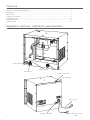
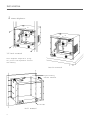
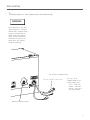
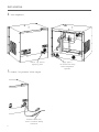
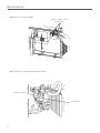
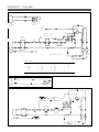
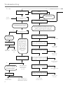
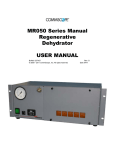
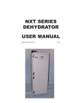
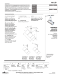
M T-600 Series Dehydrators
Installation/Operator s Manual
Contents
Controls, Indicators and Connectors ............................................. 2
Installation ................................................................ 4
Maintenance .............................................................. 8
Schematic Diagrams ........................................................ 9
Troubleshooting ............................................................ 10
Replacement Parts .......................................................... 12
Technical Data ............................................................. 12
Dehydrator Controls, Indicators and Connectors
On-off switch
Circuit breaker
Pressure gauge
Hour meter
Power cable port
Air outlet port
Power cable
Air outlet connector
2
Low pressure alarm
cable
Unpacking and Inspecting the Dehydrator
1 Check for shipping damage
Check for external damage
such as dents and broken
parts. Keep packing materials
as evidence for carrier.
Note: Dehydrator weighs 68 lb
(31kg). Two persons are
required to unpack.
Check for internal damage by
l
i
fting one side, shaking the
dehydrator and listening for
loose parts.
3
Installation
2 Mount dehydrator
19" Rack mounted
Note: Dehydrator weighs 68 lb (31 kg).
Two persons are required for rack and
wall mounting.
Bench mounted
Plywood backing,
customer furnished
W all stud
W all mounted
4
Installation
3 Connect power to rack system mains distribution bus
WARNING
Power supplied to the dehydrator requires a 15-ampere
external fuse. Improper installation of ground wiring can
result in the risk of electric
shock. Consult a qualified
electrician if you have any
doubt about your present
electrical grounding.
AC Power Connection
120 Vac, 60 Hz U.S.A. Plug
230 Vac, 50 Hz
Stripped Leads for InCountry Mains Plug:
Line - brown wire
Neutral - blue wire
Ground - green wire
with yellow stripe
Additional chassis ground.
5
Installation
4 Test dehydrator
Remove cap before
applying power
5 Connect low pressure alarm output
Customer alarm wire.
Power off before making
connection.
6
Apply power 20 second time delay
before dehydrator
operates.
Installation
6 Connect air outlet
Air line
connector
Air outlet
To transmission
line
7 Purge transmission line
Open far end of transmission line.
Operate dehydrator for 10 hours and then close the
transmission line.
If this is not possible, pressurize the line and allow it to
stabilize one hour. Bleed the system at a junction (not at
the dehydrator). Repeat this procedure twelve times.
7
Maintenance
Replacing air filter element
Depress locking tab to
disassemble.
Identification of coalescing and water filters
Coalescing filter
W ater filter
8
Schematic Diagram
P1-1
P1-2
PS2
Pressure
Switch
Low
Pressure
Alarm
E2
Chassis
Ground
Power
Relay
Compressor Control
Pressure Switch
AC
Power
Power
Switch
CB1
PR1
COMP 1
PS1
QMS1
S1
Time Delay Relay
F1*
E1
Chassis
Ground
M1
Fan
Hour
Meter
* Sound deadened unit only.
W ire Colors
1
Brn
2
Blu
3 Grn/Yel
4
Red
5
Wht
6
Red
8
9
10
11
12
13
Red
Grn
Blk
Wht
Red
Red
14
15
16
17
18
19
Wht
Wht
Red
Blk
Red
Wht
20
21
22
Blk
Red
Blk
9
Troubleshooting
A
No
Start
No
Does compressor turn?
Yes
No
Normal
Operation
Continued on page 11.
Is power switch on
(lighted)?
Yes
Turn power switch on.
Lamp should light.
Did low pressure alarm
operate?
Yes
Yes
Turn external shutoff valve (included
with installation kit) to off (O) position
and observe pressure gauge.
Yes
Is circuit breaker tripped?
No
Electrical troubleshooting requires access to potentially dangerous voltages and should only be performed by a qualified electrician. Unplug unit,
remove bottom panel, check for loose connection.
Does pressure remain
constant?
No
Is 120 or 240 VAC available at terminals 1 and 4 of power switch SW1?
Apply leak detector solution to
transmission line.
W as leak found?
Yes
Repair transmission line
No
Replace pressure switch
PS2
Remove top cover.A
noticeable pressure
drop in first 30 seconds denotes a leak.
Apply leak detector
solution to exposed
fittings to isolate leak.
Use care when
applying solution to
avoid wetting the
dehydrator wiring or
electronics.
No
Correct input wiring
Yes
Is 120 or 240 VAC available at terminals 2 and 5 of power switch SW1?
No
Yes
Is 120 or 240 VAC available between
line terminals of pressure switch PS1?
Replace power
switch SW1
No
Yes
W as leak found?
Is 120 or 240 VAC available between
motor terminal of pressure switch PS1
and terminal 5 of power switch SW1?
Replace circuit
breaker CB1
No
Yes
Replace pressure
switch PS1
No
Yes
Turn unit off and remove
bottom cover. Check pressure switch and gauge
hose fittings for proper fit.
Tighten pipe fittings
or use tie wrap on
barbed fittings to
stop leak.
Is 120 or 240 VAC available between
terminals 1 and 5 of power relay?
Yes
Is 120 or 240 VAC available between
terminals 4 and 5 of power relay PR1?
W as leak found?
Yes
No
Contact Andrew
Customer Service
10
Yes
Remove bad portions of
tubing or use tie wrap on
barbed fitting to stop leak.
No
Contact Andrew
Customer Service
Replace power relay
PR1.
No
Replace power
relay PR1
Troubleshooting
B
Continued from page 10.
W ater and Coalescing Filter Bowls
Refer to page 8 for identification of water and
coalescing filters.
Normal
Operation
Do filter bowls show a
buildup of water?
No
Yes
Remove tube from fittings at bottom
of filter bowls.
Reset
breaker one time
Yes
Does water drain?
Normal Operation
Did circuit
Breaker trip again?
No
No
Check Tubing for blockage. Clean/replace.
Yes
No
Replace circuit Breaker
Does water build up again?
Yes
Normal Operation
Restored
Did replacement breaker trip?
Contact Andrew
Customer Service
No
Yes
Contact Andrew Customer
Service
C
Compressor Overhaul
No
Continue Operation
Is run time meter approaching 6000 hours?
Yes
Contact Andrew Customer
Service for overhaul or
overhaul kit.
11
Description
Compressor
115 V, 60 Hz
220 V, 50 Hz
Power Switch (S1)
115 V
220V
Circuit Breaker (CB1)
Power Relay (PR1)
115 V
220 V
Pressure Switch (PS1)
Pressure Switch (PS2)
Time Delay Module, 20 second (QMS1)
115 V
220 V
Air Intake Filters, bag of 6
Air Intake Filter, complete cartridge assembly
Dehydrator Overhaul Kit, for dehydrator
equipped with green Wilkerson filters
115 V
220 V
Coalescing Filter, complete assembly
Coalescing Filter Bowl
Coalescing Filter Element
W ater Filter, complete assembly
W ater Filter Bowl
W ater Filter Element
Type Number
ECPRS-24300
ECPRS-34300
ESWRK-31250
AE01J-A0129-006
EBREK-11576
E R LYP-13163
ERLYP-13183
ESWPR-11100
ESWPS-11200
ETMDM-11200
ETMDM-12200
AE01K-B0518-002
EFLTR-20202
AE01K-C0398-002
AE01K-C0398-003
EFLTA-12200
EFLTA-94030
EFLTA-93020
EFLTA-52100
EFLTA-94030
EFLTA-91010
Description
Type Number
Back Pressure Regulator
EVLVR-11000
Condensate Seal Assembly
AE01A-C0770
Condensate Seal Assembly Tube Fitting
EFTGS-30223
Cooling Fan, sound deadened unit
115 V, 60 Hz
EFANS-11105
220 V, 50 Hz
EFANS-12105
1/4" Tubing, clear, specify 3.5 feet
ETUBE-20201
1/4" Tubing, black, specify 20 feet
25435-4
3/8" Tubing, black, specify 20 feet
25435-5
Low Pressure Alarm Cable
AE01C-D0482-002
Pressure Gauge
EGAUG-42100
Compressor Isolators
AE01D-B0874-001
Isolator Bushings
AE01D-C0861-001
Power Cable
115 V
ECABP-12213
220 V
AE01J-A0738-051
Power Cable Strain Relief
ECABB-21110
Heat Exchanger
AE01M-D0214-001
High Temperature Hose, compressor to heat exchanger,
specify 0.5 ft
EHOSE-21002
Low Temperature Hose, heat exchanger to water filter,
specify 1.5 ft
EHOSE-33002
Hose Clamps, high and low temp. hoses
ECLMP-20090
Technical Data
Output Pressure (approx.)
8 lb/in2 (510 mbar) (51 kPa)
Output Capacity (total, approx.)
at 95% RH and 49 C (120 F)
36 ft3/h (0.6 SCFM) (1020 l/h)
Output Dew Point, minimum
at 95% RH and 49 C (120 F)
-45 C (-50 F)
Ambient Operating Temperature:
0 - 49 C (32 - 120 F)
Low Pressure Alarm Set Point (approx.) 1.0 lb/in2 (68 mbar) (7 kPa)
Electrical Power
115 VAC, 60 Hz
780 W
220 VAC, 50 Hz
720 W
Mains Breaker Size
15 amp
Air Output Connector
3/8" compression
single output with shut-off valve
Dimensions, 9 RU:
Height
15.72 in (399 mm)
W idth
19 in (482 mm)
Depth
13.5 in (343 mm)
Net Weight
68 lb (31 kg)
Telephone: 708-349-3300
FAX (U.S.A.): 1-800-349-5444
10500 West 153rd Street
Orland Park, IL U.S.A. 60462 Internet: http://www.andrew.com
Andrew Corporation
Customer Service, 24 hours: U.S.A. Canada Mexico: 1-800-255-1479
U.K.: 0800 250055 Republic of Ireland: 1 800 535358
Printed in U.S.A. 7/96
Other Europe: +44 1592 782612
Bulletin 237373 Copyright ' 1996 by Andrew Corporation