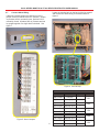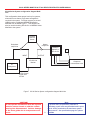
1
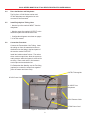
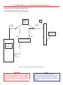
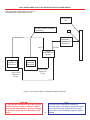
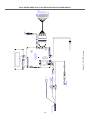
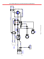
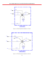
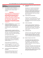
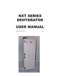
XC100 SERIES MONITOR
&
XT300 SERIES
DEHYDRATOR
USER MANUAL
Bulletin AE01B-A0510-001
Rev: A
Issue Date: July 13, 2004
XC100 SERIES MONITOR & XT300 SERIES DEHYDRATOR USER MANUAL
TABLE OF CONTENTS
SECTION 1
General Information
Introducing New XC100 Monitors for use with the XT300 dehydrator
Description
Introducing the DryLineTM Redundant Hot Standby Setup
SECTION 2
Installation
Unpacking and Inspection
Perform Pre-System Startup Test
Place the Monitor and Dehydrator
Install Polyethylene Tubing Lines
Connection Procedure
XC100 Series System configuration diagram Basic
Connect Alarm Wiring
XC100 Series System configuration diagram Multi-Line
Connect to Dry Air Cable System
Purging Procedure
Connect to Power Supply
Grounding Instructions
Plug and Outlet Configurations
Test the Unit
System Volumes, Times to Purge and Pressurize
SECTION 3
Controls and Displays
Monitor Controls
Microprocessor Control Keys
Digital Display Window
14
14
14
14
SECTION 4
Operation
Control Status and Programming
Familiarize yourself with the Displays
Main Menu
Program Mode Submenu
Pressure Monitoring and Control
Monitor Duty Cycles
Display of System Pressure
Alarm Conditions
Programming Procedure
Shutdown Procedure
15
15
15
15
15
18
20
20
20
20
20
SECTION 5
Theory of Operation
Dehydrator
Dehydrator Control
XC100 Schematic
XT300 Schematic
XT300 Compressor Schematic
21
21
21
22
23
24
2
4
4
4
4
5
5
6
6
6
6
7
8
9 & 10
11
11
11
11
12
12
13
XC100 SERIES MONITOR & XT300 SERIES DEHYDRATOR USER MANUAL
TABLE OF CONTENTS
SECTION 6
Maintenance
Semi-Annual Preventive Maintenance Inspection
In Case of Difficulty
Semi-Annual Preventive Maintenance Inspection
Check Water Filter and Coalescent Filter and Elements
Check Electrical Connections
Check Ground Wire
Check Run Time
Replace Compressor Air Filter
Carefully pull off the filter
25
25
25
25
25
25
25
25
25
25
SECTION 7
In Case of Difficulty
SECTION 8
Parts Replacement and Monitor Overhaul
Three-Year Recommended Dehydrator Spare Parts
XC100 Line Monitor Spare Parts
XT300 Dehydrator Spare Parts
Parts Replacement Procedures
Unit Shutdown and Removal
Door and Panel Removal
Replace Power Switch
Replace Circuit Breaker
Replace Compressor Control PCB
Replace Compressor
Disconnect Wiring
Disconnect Tubing
Compressor Remount and Reassembly
Replace Heat Exchanger
Replace Water Filter Element - 3000 hour Maintenance
Replace Coalescing Filter Element
Replace Cooling Fan
Replace Microprocessor Board
28
28
28
29
30
30
30
30
30
30
30
30
30
31
31
31
31
31
32
SECTION 9
Specifications
Specifications for Monitors XC100 Series
Specifications for Dehydrator XT300 Series
Optional items
33
33
33
33
SECTION 10
Customer Support
24 Hour Technical Service Hotlin
Free Loaner Program
34
34
34
SECTION 11
Warranty
36
26 & 27
3
XC100 SERIES MONITOR & XT300 SERIES DEHYDRATOR USER MANUAL
Section 1
General Information
1.1
Introducing New XC100 Monitors for use
with the XT300 dehydrator
The Andrew XC100 Monitors are a new
generation of pressurization control equipment
for antenna and transmission line systems.
They feature enhanced programmability and
controls with a bright new display and keypad.
The dehydrator features a patented membrane
separation drying technology for the industry's
best performance and reliability plus many
exclusive new features such as microprocessor
control and quiet operation.
This Manual contains the information you need
to install, operate and maintain your DryLineTM
dehydrator and XC100 Series monitor.
1.2
Figure 1 XT300 with XC100 on top
1.3
Introducing the DryLineTM Redundant Hot
Standby Setup
Description
The Andrew XC100 Series Monitor with XT300
dehydrator provides a new level of transmission
line system protection through the Redundant
Hot Standby version.
The XC100 Series monitor are designed to
control all functions of the DryLine™ XT300
Series dehydrators. The XC100 includes a
microprocessor control circuit, along with a
membrane “touch tactile” keypad and a vacuum
fluorescent display. An infrared (IR) interface is
now included which allows direct programming
and status reviews using a PDA or laptop
computer. A new event log is also recorded to
assist with system status with system status
and cycle analysis.
In this configuration, two XTC100 Series
dehydrators are connected together, providing
dry air distribution to one or more transmission
lines and common control over the operation of
both dehydrator. The system also provides
additional capacity for very large, tight systems
where the flow of a single monitor is not
sufficient for purging and initial pressurization,
but is adequate for maintaining pressure, once
established.
4
XC100 SERIES MONITOR & XT300 SERIES DEHYDRATOR USER MANUAL
Section 2
Installation
2.1
Unpack Dehydrator and Line Monitor and
Inspect for Shipping Damage
Carefully remove packing material.
Check the monitor and line monitor for shipping
damage such as dents or loose parts.
Open the covers and check for loose wires,
hoses, or components.
If anything loose, refer to the piping schematic
Figure 10 or the wiring schematic Figure 12 for
proper placement.
If there is damage or if there are any other
problems, contact Andrew Technical Service.
Telephone numbers are listed in Customer
Support Section 10.
Figure 2 Filters
If everything looks correct, close the covers.
2.2
Perform Pre-System Startup Test
Make sure power switch is in the OFF position.
Plug the monitor and dehydrator into proper
electrical outlets. Proper outlets are defined in
the specifications. Connect the 5VDC control
signal cable from the monitor to the dehydrator.
Connect the dehydrator output air line to the
monitor input. Do not connect the air lines to
the transmission lines at this time. After turning
the power switches ON, within 30 seconds the
systems will start and the display will read:
“SYSTEM PRESSURE XXX.X PSI (or KPa).
As the unit warms up, check the filter bowls
See Figures 1 to ensure condensate is being
released and not building up in each bowl.
Check the air output port at the top or back of
the unit to make sure that air is flowing out. If
problems exist, review troubleshooting
procedures in Section 7 or consult Andrew
Technical Service. If these items check out,
turn power switch OFF, unplug the unit.
For the Redundant Hot Standby configuration,
there is a control line from the master unit
which connects to the input line on the slave
unit.
5
XC100 SERIES MONITOR & XT300 SERIES DEHYDRATOR USER MANUAL
2.4
Place the Monitor and Dehydrator
The DryLineTM XC100 Series monitor and
XT300 dehydrator are designed to be rack
mounted or shelf mounted.
2.5
Install Polyethylene Tubing Lines
* Monitor input line marked “INPUT” from the
dehydrator.
* Monitor output line marked “OUTPUT” to the
distribution panel and transmission lines.
* Configuration diagrams are shown on pages
7-10 of this manual.
2.6
Connection Procedure
Connect the Transmission Line Tubing. Insert
the tubing run from the transmission lines or
distribution into the fitting in the back panel of
the monitor marked "OUTPUT".
Install the isolation shutoff valves. The valves
when used on output lines, allow the system to
retain pressure while the system is removed for
servicing. Place each valve in line between
each output and transmission line.
For Redundant Hot Standby, use the Tee fitting
(optional) to connect the output lines together
(from the master and slave units).
OUTPUT Waveguide
XC100 Power Cord
Air INPUT from
Dehydrator
5VDC Remote Cable
XT300 Power Cord
Figure 3 Transmission Line Connections
6
XC100 SERIES MONITOR & XT300 SERIES DEHYDRATOR USER MANUAL
XC100 Series System configuration diagram Basic
This configuration shows proper hook up for systems
when only a single waveguide is required in the system.
Isolation
Shut-off
Valves
*
Montor
output line
Dehydrator
output line
Primary Large
Wave Guide
OUTPUT
INPUT
XC100 Line Monitor
XT
Dehydrator
5VDC Control
Signal
from XC100
Figure 4 XC100 Series System configuration diagram
CAUTION!
Do not operate the Monitor with the system
isolation valves closed or with the remote
sensing line disconnected. Serious damage
to the wave guide due to overpressure can
occur.
7
* NOTE!
To provide extra overpressure protection, a
secondary popoff valve may be added at this point
that is closely matched to the maximum system
safe pressure. See specification page for options
available
XC100 SERIES MONITOR & XT300 SERIES DEHYDRATOR USER MANUAL
2.7
Connect Alarm Wiring
Locate the terminal strip on the back of the line monitor
and connect the alarm wiring to terminals shown in
figure 6.
If Normally Closed contacts are desired, move the
jumper on the PC boards to the N.C. position. Jumper
on positions A-B for normanlly open, position B-C for
normanlly closed. All alarms are dry contacts and can
be ganged together if a single alarm is desired. See
figure 5.
JP2
JP3
JP4
JP5
JP6
JP7
Figure 6 Terminal strip
Table 1 Terminal strip
Function
Terminal
Symbol
High Pressure
Common
-
High Pressure Normally Open
+
High Humidity
-
Common
High Humidity Normally Open
Excess Run
Common
-
Excess Run
Normally Open
+
Low Pressure
Common
-
Low Pressure Normally Open
Figure 5 Alarm Jumpers
8
+
+
Power Fail
Common
-
Power Fail
Normally Open
+
Jumper
JP7
JP2
JP4
JP6
JP5
XC100 SERIES MONITOR & XT300 SERIES DEHYDRATOR USER MANUAL
XC100 Series System configuration diagram MultiLine
This configuration shows proper hook up for systems,
when when more than a single wave waveguide is
required in the system. For larger systems, a second
LM400 monitor or additional MN6600 Distribution
Maniflods can be added Figure 7. This diagram can
also be used for hooking DP-4A-001 or MN6600 Series
Manifold to the system.
Isolation
Shut-off
Valves
Montor
output line
Dehydrator
output line
LM400 or
MN6600 or
DP-4A-001
INPUT
*
OUTPUT
XC100 Line
Monitor
Outputs to
transmission Lines
XT
Dehydrator
5VDC Control
Signal from
XC100
Figure 7 XC100 Series System configuration diagram Multi-Line
CAUTION!
Do not operate the Monitor with the system
isolation valves closed or with the remote
sensing line disconnected. Serious damage
to the wave guide due to overpressure can
occur.
9
* Note
To provide extra overpressure protection a
secondary popoff valve may be added at this point
that is closely matched to the maximum system
safe pressure. See specification page for options
available
XC100 SERIES MONITOR & XT300 SERIES DEHYDRATOR USER MANUAL
This configuration shows proper hook up for a
redundant system configuration Figure 8.
Transmission
Line
Dehydrator outputs connected
with tee fitting
*
To distribution
(LM400/MN6600
or DP-4A-001)
INPUT
OUTPUT
XC100
Redundant Line
Monitor
XT
Redundant
Dehydrator
5VDC control
Signal from
XC100
XT
Redundant
Dehydrator
5VDC control
Signal from
XC100
Figure 8 XC100 Series System configuration diagram Multi-Line
CAUTION!
Do not operate the Monitor with the system
isolation valves closed or with the remote
sensing line disconnected. Serious damage
to the wave guide due to overpressure can
occur.
10
* Note
To provide extra overpressure protection a
secondary popoff valve may be added at this point
that is closely matched to the maximum system
safe pressure. See specification page for options
available
XC100 SERIES MONITOR & XT300 SERIES DEHYDRATOR USER MANUAL
2.8
During the OFF cycle, the dehydrator is
designed to allow a small amount of system air
to bleed back through the membrane dryer.
This air maintains the dryness of the membrane
dryer. As system air bleeds back through the
dryer, additional system moisture is continually
removed, lowering the system dew point even
further.
Connect to Dry Air Cable System
CAUTION
Check the system pressure rating before
connecting the dehydrator/monitor to the
transmission line system. The pressure
settings must be adjusted to match the ratings
of the waveguide components. See Section 4.
To insure that all internal dehydrator
components are properly dried; operate the unit
for at least 45 minutes prior to connecting the
output air line to the primary waveguide.
Your system is now up and running at the
factory programmed settings. To become
familiar with the microprocessor controls and to
change the settings, proceed to Section 3,
Controls and Displays.
If the transmission lines have not been purged,
take the following steps to dry the system;
otherwise, proceed to Section 3, Controls and
Displays.
2.8.1
Connect the alarm wiring to the terminals on
the back of the XC100. Refer to the label on
the alarm board or the schematic for the proper
connections.
Purging Procedure
2.9
Determine total volume of the pressurized dry
air cable system to be connected to the
monitor. Refer to "Table 2 - Times to Purge and
Times to Pressurize." Remember if the
Redundant Hot Standby option is used, these
times can be cut in half (approximately).
The XC100 Series and XT300 Series can be
plugged into a standard 15-amp power
receptacle of the rated voltage.
Connect the monitor to a properly grounded
power outlet. Power is specified in Section 9,
Physical Specifications.
Open the opposite end of the cable system
from the monitor for purging.
2.9.1
Operate the monitor (after the initial 45 minute
drying period) to deliver dry air into the
pressurized air system until a total of 3 volumes
have been pumped through the entire system.
Check cycle timing. Compressor on time
should be no more than 10% of off time for
maximum life. If not:
System may not be properly sized.
2.
Leaks may exist. Check using Snoop
or detergent water.
3.
Normal connector leakage may be
greater than expected.
Grounding Instructions
This product should be grounded. In the event
of an electrical short circuit, grounding reduces
the risk of electric shock by providing an
escape path for the electric current. This
product is equipped with a cord having a
grounding wire and a grounding plug. It should
be plugged into a properly installed outlet that is
grounded in accordance with all local codes
and ordinances.
Check the humidity in the system using the
humidity alarm, if so equipped. Perform this
check after the far end of the system has been
closed and the system has been stabilized for
at least 5 hours.
1.
Connect to Power Supply
WARNINGS
Improper installation of the grounding
plug can result in a risk of electric
shock. If repair or replacement of the
cord or plug is necessary, do not
connect the green grounding wire to
either flat blade terminal. Check with
a qualified electrician or serviceman if
you have any questions regarding
grounding or if in doubt as to whether
the product is properly grounded.
11
XC100 SERIES MONITOR & XT300 SERIES DEHYDRATOR USER MANUAL
Connection to a Halo Grounding System: A #10
grounding stud is located at the inside power
entry area of the dehydrator chassis and on the
back of the monitor for direct connections to a
halo grounding system. Connect using a No.6
copper stranded wire, terminated at the ground
stud with a proper ring tongue crimp-on
terminal.
2.9.2
Plug and Outlet Configurations
Make sure that the units are connected to an
outlet having the same configuration as the
plug. Do not modify the plug. If it will not fit the
outlet, have a proper outlet installed by a
qualified electrician. Do not use an adapter. If
the product must be reconnected for use on a
different type of electric circuit, qualified service
personnel should make the reconnection.
2.10
Test the Unit
Turn ON the monitor and dehydrator. The
display should indicate 0.0 pressure within thirty
seconds. The humidity alarm, low-pressure
alarm, pressure reading and, eventually, the
excess run time alarm (if so equipped) should
flash in sequence in the display window. The
alarm conditions exist because the unit is not
connected to the system.
12
XC100 SERIES MONITOR & XT300 SERIES DEHYDRATOR USER MANUAL
TABLE 2 System Volumes, Times to Purge and Pressurize
Line Type
Time to Purge 1000 ft
(305 m) in Hours
per 3 Volumes
Volumes
ft3 per
1000 ft
liters per
1000m
Time to Pressurize to
Operating Pressure In Hours
Per 1000 ft (305 m2.)
XT300
XT300
5.46
10.4
17.33
.613
1.173
1.960
HELIAX Coaxial Cable, Pressurized to 5 lb/in2 (35 kPa)
3"
4"
5"
36.7
69.9
117.0
3410
6494
10870
HELIAX Elliptical Waveguide, Pressurized to 5 lb/in2 (35 kPa)
EW34
EW28
EW20
EW17
25.0
36.0
60.5
71.0
2323
3345
5621
6596
3.70
5.33
8.96
10.52
.413
1.200
1.013
1.187
5.85
6.38
.667
.720
7.21
12.44
28.74
51.41
.813
1.413
3.233
5.826
Circular Waveguide, Pressurized to 5 lb/in2 (35 kPa)
WG269
WC281
39.5
43.1
3670
3746
Rigid Transmission Line, Pressurized to 5 lb/in2 (35 kPa)
3-1/8”
4-1/16”
6-1/8”
8-3/16”
48.7
84.0
194.0
347.0
4524
7804
18023
32236
TABLE 3 Pressure Ratings
Max. Pressure
Antenna
Rating, lb/in2 (kPa)
uMx-459
UMx-611
HPX12-6511C
P-186
2 GHz Antennas
CAUTION
uMx-459, -465,-611 and HPX12-6511C and P186 Antennas have lower pressure ratings
than the Antennas as indicated in the chart
below.
5
5
5
2
3
(35)
(35)
(35)
(14)
(21)
Maximum pressure ratings for reference, contact the
antenna group for actual pressure ratings. Specific
feeds and pressure windows may have reduced
pressure ratings.
13
XC100 SERIES MONITOR & XT300 SERIES DEHYDRATOR USER MANUAL
Alarm Condition Display. A flashing display
indicates that an alarm condition exists.
The display is factory set for English language
and English units. It can also be set for metric
units.
Section 3
Controls and Displays
This section explains the functions of the controls and
displays used for operation and programming of the
monitor.
3.1
Monitor Controls
ON-OFF
Double pole power switch controls both
sides of the line. Built-in light indicates
power is ON.
Circuit
Breaker
White tab indicates overload condition.
Resettable.
Fuse
On front door.
3.2
Microprocessor Control Keys
SELECT
Advances display (scrolls ahead) to the
next display or program mode without
changing the values in the microprocessor
memory.
ENTER
Enters into the microprocessor memory
the values displayed in the window and
advances display (scrolls ahead) to the
next program or display mode.
Numerically increase displayed settings in
display window. When depressed longer
than 1/2 second scrolling will occur at a
faster rate.
Numerically decrease displayed settings in
display window. When depressed longer
than 1/2 second scrolling will occur at a
faster rate.
VIEW
LOG
3.3
Used to allow the user quick access to the
system event log. After depressing this
button, the most recent event will be
displayed. The upand down arrow buttons
may be used to browse the log.
Digital Display Window
The window displays three types of information:
System Status Information. Displays system
pressure and total run time.
Program Control Prompts. Used for setting duty
cycle ON/OFF pressures and alarms.
14
XC100 SERIES MONITOR & XT300 SERIES DEHYDRATOR USER MANUAL
Section 4
Operation
4.1
SELECT
3.
Control Status and Programming
XC100 Series monitors have a microprocessor
based control board for monitoring and control
of the monitor and setting the programmable
alarms. It comes factory set for English
language and English units.
ENTER
pressing the
to [COMP 5.0 PSI].
Figure 9 shows the various modes, which may
be viewed, in the display window. Main Menu
displays are shown in the first column.
Program Mode Submenu displays are shown in
the second column.
4.2
Familiarize yourself with the Displays
4.2.1
The Main Menu
4.2.2
The Program Mode Submenu
SELECT
1.
Press the
key and proceed from
system pressure to [PROGRAM MODE].
ENTER
2.
SELECT
Press the
button and the display will
indicate "PROGRAM MODE".
Press the
key and proceed to the
Program Mode Submenu. [COMP ON 0.5] will
now appear on the display. At this point, the
display will be as follows, prompting the user for
a new password: “password 0/1 2/3 4/5 6/7 8/9
the default password is “111111”. The following
are used for password entry:
Select
Up Arrow W
Down Arrow
Enter
View Log
SELECT
2.
key and proceeding back
If your monitor is equipped with all options, all
of the screens shown in the flow chart will
apply. The modes pertaining to high-pressure,
high humidity (fixed at 7.5% R.H.) and excess
run time, as well as multi-channel manifold
capability are options.
First, become familiar with the Main Menu.
Turn the monitor. In about 30 seconds, the
monitor will start and begin to pressurize the
system. Upon power up the system will do a
set of internal diagnostics and mean while
display as follows: “X controller revision XX.X.”
If a power-up test failure is detected the
following is displayed: “system pressure XXX.X
PSI (kPa).
1.
Press
and you will return to system
pressure, or, if the excess run alarm has been
purchased, "CLEAR RUN TIME" will appear.
This feature is used to clear the alarm by
Press the
button again and the Total
Run Time will appear as "XXXX.X HOURS" and
indicate total hours since initial turn-ON.
Note
for the Redundant Hot Standby
0/1
2/3
4/5
6/7
8/9
The following sections describe the various
programmable functions and the associated
sub-functions in detail.
SELECT
version, the
button can be pressed
again and total run time will appear as;
"XXXX.X hours B" and indicate total
Dehydration B hours since initial turn ON.
15
3.
Compressor Count
This valve is set to “1” for a single compressor
up to “4” when used with multiple compressors
in the Redundant Hot Standby mode. Values =
“1-4”.
4.
High Pressure Tank
Set this valve to “NO” unless the high pressure
tank option was purchased. Values = “Y or N”.
XC100 SERIES MONITOR & XT300 SERIES DEHYDRATOR USER MANUAL
5.
SET DATE (month)
2 digits for month of the year.
values = “01 - 12”
6.
SET DATE (day)
2 digits for day of the month.
values = “01 - 31”
BACKUP COMP ON PRESS
Used only with multiple compressor systems
set to operate in redundant hot standby mode.
This is set to the desired start pressure for the
backup compressor(s). Format is XXX.X PSI
(kPa). Values = “0.3 - 15.0”.
7.
SET DATE (year)
2 digits for year.
values = “00 - 99”
NOTE
Must be set below primary compressor ON
set point.
8.
SET TIME (hour)
2 digits for hour of the day.
values = “00 - 23”
9.
SET TIME (minutes)
2 digits for minutes of the hour.
values = “00 - 59”
10.
COMP RUN TIME ALARM
Set this to a time above the normal runtime on
the system.
values = “5 - 240”
11.
COMPRESSOR ON
Set this the desired start pressure in PSI (or
kPa) format is XXX.X PSI. Values = “0.3 15.0” for standard unit or “0.3 - 100.0” for the
high pressure option.
12.
COMPRESSOR OFF
Set this the desired start pressure in PSI (or
kPa) format is XXX.X PSI. Values = “0.3 15.0” for standard unit or “0.3 - 100.0” for the
high pressure option.
13.
LOW PRESSURE ALARM
Set this the desired low pressure alarm
threshold. Format is XX.X PSI (kPa). Values =
“0.1 - 15.0”.
15.
NOTE
Must be set below compressor ON set point.
Recommended setting is at least 0.3 PSI
below compressor ON values.
14.
HIGH PRESSURE ALARM
Set this to the desired high pressure alarm
threshold. Format is XX.X PSI (kPa). Values =
0.1 - 16.0”
NOTE
Must be set above compressor OFF set
point. Recommended at least 0.3 PSI above
OFF value.
16
16.
COMP OVERHAUL TIME
Factory only setting 3000 hours.
17.
KEYPAD INACTIVITY
Format is XX seconds. Factory set for 45
seconds.
18.
SYSTEM PRESSURE HI RES
If set to “YES”, this setting will display system
pressure two decimal places of resolution. Set
to “NO” except when system pressures are very
low or the ON and OFF pressure differential is
very small.
19.
ENTER NEW PASSWORD
The factory set password is “111111”. User
many enter a new password and depress
“ENTER” or depress the “SELECT” button to
cancel the change.
XC100 SERIES MONITOR & XT300 SERIES DEHYDRATOR USER MANUAL
Notes
17
XC100 SERIES MONITOR & XT300 SERIES DEHYDRATOR USER MANUAL
Power-Up
System Check
Fault
Found
OK
System Pressure
XXX.X PSI (or kPa)
Scroll
Ahead
SELECT
PROGRAM MODE
Enter
or
Password
0/1 2/3 4/5 6/7 8/9
ENTER
or
Scroll
Ahead
Use default "111111"
SELECT
Compressor Runtime
XXXX.X HOURS
Scroll
Ahead
ENTER
Compessor Count
1
SELECT
Clear Runtime Alarm Hit
Enter to Clear
or
ENTER
To
Cancel
Alarm
Scroll
Ahead
or
ENTER
To
Record
Change
SELECT
or
Scroll
Ahead
High Pressure Tank?
N
SELECT
ENTER
To
Record
Change
ENTER
To
Record
Change
ENTER
To
Record
Change
ENTER
To
Record
Change
ENTER
To
Record
Change
or
or
Scroll
Ahead
SELECT
Set Date (month)
MM
or
or
Scroll
Ahead
SELECT
Set Date (day)
DD
or
or
Scroll
Ahead
SELECT
Set Date (year)
YY
or
or
Scroll
Ahead
SELECT
Set Time (hour)
HH
or
Scroll
Ahead
SELECT
Figure 9 Program Mode Submenu
18
or
XC100 SERIES MONITOR & XT300 SERIES DEHYDRATOR USER MANUAL
ENTER
To
Record
Change
ENTER
To
Record
Change
ENTER
To
Record
Change
or
Set Time (Minutes)
MM
or
Scroll
Ahead
SELECT
or
Comp Runtime Alarm
XXX Minutes
or
Scroll
Ahead
SELECT
or
Compressor ON
XX.X PSI (kPa)
or
Scroll
Ahead
SELECT
or
Low Pressure Alarm
XX.X PSI (kPa)
ENTER
To
Record
Change
or
Scroll
Ahead
SELECT
ENTER
To
Record
Change
ENTER
To
Record
Change
ENTER
To
Record
Change
ENTER
To
Record
Change
ENTER
To
Record
Change
or
High Pressure Alarm
XX.X PSI (kPa)
or
Scroll
Ahead
SELECT
or
Backup Comp ON Press
XX.X PSI (kPa)
or
Scroll
Ahead
SELECT
or
Comp Overhaul Time
XXXX HRS
or
Scroll
Ahead
SELECT
or
Key Pad Inactivity
XX MIN
or
Scroll
Ahead
SELECT
or
Enter New Password XXXX
or
SELECT
Figure 10 Figure 9 Program Mode Submenu Continued
19
XC100 SERIES MONITOR & XT300 SERIES DEHYDRATOR USER MANUAL
4.3
Pressure Monitoring and Control
4.3.1
Monitor Duty Cycles
4.4
Programming Procedure
Use the SELECT key to advance through the
series of prompts without changing the
programmed values. If you change a value and
want to save it to memory, use the ENTER key,
which will also advance you to the next feature.
The monitor is programmed at the factory to
start when the output pressure of the
dehydrator drops to .5 lb/in2 (3 kPa) and stop
when the pressure reaches 5 lb/in2 (35 kPa).
That is the recommended pressure range for
most antenna and transmission line
components, which have a rating of at least 5
lb/in2 (35 kPa).
With the "PROGRAM MODE" prompt displayed
SELECT
Some system components, however, have
lower pressure ratings. Using the procedures
described below, XC100 Series monitors can
be programmed for any start/stop pressure
combination in the 0.3 - 15.0 lb/in2 (2-103 kPa)
range.
in the display window, press the
key
to precced to the first programmable feature.
4.5
When removing your monitor or dehydrator
from service, you may need a substitute dry air
source. Call Andrew Technical Service.
Telephone numbers are listed in Customer
Support section 10.
For the Redundant Hot Standby version, the
master unit is programmed to operate at 1.0
PSI (7 kPa) and the slave unit is programmed
to start at 0.5 PSI (3.5 kPa). Both units are set
to stop at 5.0 PSI (35 kPa).
4.3.2
Shutdown Procedure
Before turning OFF the unit, notify personnel
that alarms may be activated.
Display of System Pressure
To shut down the XC100 Series unit first turn
the dehydrator power switch to the off position,
turn the monitor ON-OFF power switch to the
OFF position and close the isolation shutoff
valves located in the output/input lines to retain
system pressure.
The monitor output pressure SYSTEM
PRESSURE 0.0 PSI is the initial display as
power is applied to the unit.
As shown in Figure 9, Main Menu, pressing the
Disconnect by unscrewing the poly tube
compression fittings located at the back or top
of the units.
SELECT
Key will display "PROGRAM MODE"
on the display window.
4.3.3
Alarm Conditions
Alarm conditions, except high humidity, are
defined by the programmed settings entered
into the microprocessor as described below.
Alarm contacts are included in the unit and
wiring terminals are located on the back of the
monitor. When an alarm condition exists, the
normally open contacts are closed, thereby
activating a remote alarm (not included). Also,
the alarm condition will flash continually on the
display window until the alarm condition is
corrected. In the case of the excess run alarm,
the alarm must be cleared as described in the
programming section.
20
XC100 SERIES MONITOR & XT300 SERIES DEHYDRATOR USER MANUAL
Section 5
Theory of Operation
5.1
Dehydrator
The patented drying system begins at the
compressor, where filtered ambient air (refer to
piping schematic Figures 4, 7 and 8) is
compressed. The compressed air is then
cooled and condensed in the heat exchanger
after which water droplets are separated in the
water filter. The saturated air then passes
through a coalescing filter for the removal of
additional water and then into the patented
membrane cartridge where the remaining water
is removed by pressure differential.
The water separated in the filters is blown to a
pan on the head of the compressor and is
evaporated by the heat of compression. The
flow of the water is controlled by a timer
controlled solenoid.
The membrane tube separates moisture from
air by a pressure differential across
semipermeable fibers. The water vapor and a
small amount of the air permeate through the
filter walls leaving the exiting air with a reduced
water vapor content of -45°C (-50°F) dewpoint.
The air that permeates through the fibers
purges the water vapor out of the tube's vent
ports.
This patented drying process contains no
moving parts, thus reducing maintenance and
increasing reliability.
5.2
Dehydrator Control
The ultra-dry air exits the dehydrator at the top
(or back) of the unit. Low pressure, High
pressure, High Humidity, and excess run alarms
are tapped into the air line within the
dehydrator.
21
MAINS POWER CORD
22
BLUE
BROWN
GRN/YLW
5
4
E1
K5
YELLOW
PURPLE
BLUE
CB1
CIRCUIT
BROWN BREAKER
SOLENOID
OVER PRESSURE
2
1
S1
ON/OFF
SWITCH
GND
CHASSIS
E1
40
39
6
YELLOW
PURPLE
GRN/YLW
6
1
2
1
1 1
5
2
6
5
P4
POWER
2
1
2
1
KEYPAD
CABLE
KEYPAD
P2
1
1
1
1
1
1
TO DEHYDRATOR - COMPRESSOR
CONTROLLER - CONNECTOR P1
1
P6
P7
P8
P9
COMP1 COMP2 COMP3 COMP4
AE01J-A1998-001
MICROPROCESSOR
CONTROLLER
P5
SOL
DISPLAY
P1
DISPLAY CABLE
SERIAL
P2
Figure 10 XC100 Schematic
CHASSIS
GND
40
1
5
1
9
***
P3
39
P13
HUM
P12
TEMP
P11
ALARM OUT
P10
LED
1
1
DISPLAY
GREEN
BROWN
PINK
TAN
BLUE
WHITE
BLACK
RED
GRAY
ORANGE
YELLOW
PURPLE
GRN
BLK
RED
1
AE01J-A1998-101
1
DISPLAY
P1
HUMIDITY
SENSOR
9
RED
GREEN
BROWN
BLUE
WHITE
GRAY
ORANGE
YELLOW
PURPLE
ALARM TERMINALS
10 10 BLACK
8
7
7
9
6
6
8
4
5
4
3
3
5
1
2
TB1
1
2
XC100 SERIES MONITOR & XT300 SERIES DEHYDRATOR USER MANUAL
IEC
CONNECTOR
N
G
L
SIGNAL
CABLE
23
GRN
CHASSIS
E1
GND
ORN
RED
PI-2
4
1
5
FAN
F1
S1
2
CB1
BLK
Figure 11 XT300 Schematic
HOUR
METER
M1
WHT
BLK
CIRCUIT
BREAKER
WHT
BLK
ON/OFF
SWITCH
BLK
RED
1+
4
2
3+
K1 (PR1)
BLK
P1-1
WHT
POWER
RELAY
DRAIN
S1
SEE FIGURES 12 AND 13
RET
LINE
GND
E1
CHASSIS
GND
XC100 SERIES MONITOR & XT300 SERIES DEHYDRATOR USER MANUAL
XC100 SERIES MONITOR & XT300 SERIES DEHYDRATOR USER MANUAL
GREEN
GND
RED
BLUE
LINE
BLACK
ORANGE
COMP
C1
BRN
BRN
MOTOR
START
CAP
WHITE
RET
-XXX1X ONLY
Figure 12 XT300 Compressor Schematic for 115 VAC
GND
GREEN
ORANGE
RED
LINE
BLACK
BLUE
COMP
C1
RET
WHITE
BRN BRN
MOTOR
START
CAP
-XXX2X ONLY
Figure 13 XT300 Compressor Schematic for 230 VAC
24
XC100 SERIES MONITOR & XT300 SERIES DEHYDRATOR USER MANUAL
6.3.1
Section 6
Maintenance
6.0
The dehydrator requires maintenance
semiannually and/or after each 3000 hours of
operation to ensure continued reliable
operation.
Verify there is no excessive water build-up in
the filter bowls. If there is excessive water,
refer to the troubleshooting procedures in
Section 7 for corrective action. Replacement of
the water filter and coalescent filter and their
associated elements and bowls is covered in
the parts replacement section of this manual.
Refer to Section 8.
WARNINGS
Service personnel should observe all
safety regulations. Do not perform
maintenance on equipment without
first turning OFF the main power
supply. Under certain conditions,
dangerous potentials may exist when
the main power supply controls are in
the off position. Only qualified
technicians should attempt to effect
maintenance or repairs on electrical
equipment.
6.3.2
Semi-Annual Maintenance. The semi-annual
maintenance consists of a preventive
maintenance inspection and replacement of the
compressor air filter. These tasks can be
performed easily in the field as described
below.
6.3.4
Check Run Time
Check the run time on the monitor to determine
the duty cycle of the dehydrator. If the monitor
has been running more than 10% of the time,
check for system leaks. Also check to see if it
is time to schedule the 3000-hour maintenance.
The monitor overhaul kit, see Section 8.1,
includes all the necessary parts and
instructions. Or, if you prefer, Andrew offers a
monitor overhaul service. Contact Andrew
Technical Service. Telephone numbers are
listed on Section 10.
6.3.5
Replace Compressor Air Filter
The air filter protects the compressor from
contamination and extends the service life of
the compressor. It is made of open cell
material and should be replaced every six
months or more often if the unit is located in a
dusty environment.
Refer to Sections 8.4.7 and 8.4.10 for
procedures to replace water filter elements.
6.3
Check Ground Wire
Check for proper ground wire connection to
protect operations personnel. A green ground
wire is attached between the power terminal
strip and the monitor chassis. The ground lug
screw or stud nut must be tight to provide a
proper ground.
3000 hour Overhaul. A monitor overhaul is
required after the compressor has run a total of
3000 hours, as indicated on the compressor run
time meter. The monitor overhaul includes a
compressor overhaul, water filter, high tempera
ture tubing and hose clamps.
6.2
Check Electrical Connections
Check for loose or corroded electrical
connections. A loose terminal can cause erratic
operation and unnecessary downtime. Check
the screw-on and push-on terminals and tighten
as required.
6.3.3
6.1
Check Water Filter and Coalescent Filter and
Elements
In Case of Difficulty. If the monitor will not
operate or if there are other problems, refer to
the troubleshooting procedures in Section 7.
Carefully pull off the filter cover and remove the
filter element. Install the new filter element and
replace the filter cover, being certain that it is
completely seated. To replace the filter housing,
unscrew the housing from the compressor head
and replace with new filter housing.
Semi-Annual Preventive Maintenance
Inspection
Inspection includes checking for loose or
damaged hoses, fittings and electrical
connections. Check the following items:
25
XC100 SERIES MONITOR & XT300 SERIES DEHYDRATOR USER MANUAL
NOTE:
Run the dehydrator to dry it out prior to
connecting it to the system. Run it until the
high humidity alarm clears (if so equipped).
The drying process should take about 45
minutes, if the membrane dryer was not
saturated. If the membrane dryer was
saturated, drying may take up to 48 hours.
Section 7
In Case of Difficulty
If you experience difficulty with your monitor or
dedydrator, use the troubleshooting procedures
described below. Perform the tests, inspections
and corrective actions corresponding to the
problem in the order listed. See pages 7-10 for
piping connections and Figure 10 for wiring.
Section 8 lists replaceable parts.
WARNING:
High voltage exists inside the units.
Disconnect the units whenever
performing troubleshooting
operations.
Andrew Technical Service. If you cannot
correct the problem or if there are other
difficulties, contact the Andrew Technical
Service nearest you. Telephone numbers are
listed on page 34.
Table 4 Troubleshooting Procedure
Problem/Condition
Solution
Check the breaker adjacent to the ON/OFF switch if, tripped (white
indicator exposed) then reset breaker by depressing.
If ON/OFF switch light still fails to light, make sure that unit is plugged
Monitor or dehydrator ON/OFF switch does not in and the power outlet is operating.
light, unit does not run.
If you still have no light, unplug unit, open the front door panel and
check for loose connections. Refer to wiring diagram for proper wire
connection.
ON/OFF switch does not light, unit runs.
Monitor ON/OFF switch does not light and the
display is blank.
Disconnect ac power, open front doors, check for loose connections
(refer to the wiring diagram for proper connections). Replace cover and
reconnect ac power.
Replace ON/OFF switch if condition persists.
Check ac voltage connection to the unit.
Check circuit and breaker, push to reset.
If problem persists, disconnect monitor from ac power, open front door
panel and check for loose connections (refer to the wiring diagram).
Close front door, reconnect power and turn ON unit. if problem is not
corrected, contact Andrew Technical Service for assistance.
NOTE:
This problem can be caused by a lightning induced power surge.
The monitor is equipped with surge protectors which may cause
the fuse to blow when a surge is encountered.
Check circuit breaker push to reset
Disconnect unit from ac power, open front door panel and check for
loose connections (refer to wiring diagram).
On/OFF switch lights display is blank.
Dehydrator starts and stops before reaching
sufficient line pressure.
WARNING:
High voltage is present inside the enclosure and on the
power supply board at this point. Failure to comply may
result in INJURY or DEATH.
Check compressor ON and compressor off settings on line monitor
Check for kinks in line tubing. Replace tubing where necessary.
26
XC100 SERIES MONITOR & XT300 SERIES DEHYDRATOR USER MANUAL
Low pressure alarm on display.
Verify that the Low Pressure Alarm Set Point is below the compressor
ON set point. Isolate the low pressure condition by checking all fittings
with soapy water. Make sure that all system tubing is properly seated
in the fittings. Check for loose interface points and holes in the
transmission lines. Correct any conditions that exist where pressure is
leaking. If the condition persists, call Andrew Technical Service for
assistance.
Verify the compressor turn OFF and high pressure alarm settings as
shown in Sections 4.2.2. The High Presssure Alarm set point must be
above the the compressor OFF set point
High Pressure alarm on display.
The High Pressure Alarm can be triggered by ambient temperature
rises. If this is a reoccurring problem, the set points should be adjusted
to increase the differential between compressor OFF and High
Pressure Alarm values. Contact Andrew Technical Service for further
assistance.
Check the dehydrator for build-up of water in the filter bowls.
Humidity alarm on display.
CAUTION:
If there is a build-up of water in the water filter bowl, use a soapy water
solution to check for leaky fittings in the dehydrator. If no leak can be
found, the problem is probably with the compressor. Rebuild kits for
each monitor are specified in Section 8. The unit may also be returned
to Andrew for repair. Contact Andrew Technical Service for further
assistance.
The humidity sensor is light sensitive.
Note:
DO NOT remove it from the brass
Once the problem has been corrected, run the dehydrator off line
fitting when the monitor is powered
until the humidity alarm clears. If the membrane dryer has been
up.
saturated, this process can take up to 48 hours of continuous
running.
Check the programming of the excess run time display as shown in
section 4.2.2. The set point should be at least 50% above the normal
run time.
Excess run time alarm on display.
The unit is cycling ON and off at less than a 30 minute interval. See
troubleshooting section "Dehydrator starts and stops before reaching
sufficient line pressure".
Check system for leaks. See troubleshooting section "Low pressure
alarm on display".
Unit turns on for only a few seconds, and then
shuts OFF.
Check the ac voltage supply to the unit
27
XC100 SERIES MONITOR & XT300 SERIES DEHYDRATOR USER MANUAL
NOTICE:
To provide continuous reliable operation the
dehydrator must be overhauled every 3000
hours of compressor operation. The
monitor overhaul kit, listed below, contains
all necessary parts. Alternatively, you may
send your dehydrator to Andrew for
overhaul.
Section 8
Parts Replacement and Overhaul
Andrew dehydrators have been designed to
provide many years of trouble-free service and
will require minimal maintenance. The display
panel on the monitor contains, as one of the
standard features, a reading of actual
compressor run hours.
Table 5 Three-Year Recommended Dehydrator Spare Parts
Item
1
2
3
4
5
6
7
8
9
QTY.
Part Number
1
Compressor Air Intake Filters
(bag of six)
1
EFLTR-91101
2
Compressor Air Intake Filters
(complete assembly housing w/filter)
1
EFLTR-20201
3
Dehydrator Overhaul Kit. Includes compressor overhaul
kit, high temperature hose clamps XT300
1
AE01K-C0398-001
Table 6 XC100 Line Monitor Spare Parts
Item
QTY.
Power Switch 115V
1
Power Switch 230V
1
Circuit Breaker 3 amp
1
Microprocessor Controller PBC 115V
1
Microprocessor Controller PBC 230V
1
Display PBC
1
Keypad
1
Humidity Sensor Cable Assy
1
1
Monitor/Dehydrator Signal Cable
28
Part Number
AE01J-A0129-005
AE01J-A0129-006
EBREK-10376
AE01J-A2007-002
AE01J-A2007-001
AE01J-A2007-101
AE01D-D1673-001
AE01C-D0785-036
AE01C-D0796-001
XC100 SERIES MONITOR & XT300 SERIES DEHYDRATOR USER MANUAL
1
2
3
4
5
6
7
8
9
10
11
12
13
14
15
16
17
18
19
20
21
22
23
24
Table 7 XT300 Dehydrator Spare Parts
Item
QTY.
Power Switch 115V
1
Power Switch 230V
1
Circuit Breaker 15 amp
1
Compressor 115/230V 50/60 Hz
1
Heat Exchanger
1
5.0” (12.7cm)
High Temperature Hose(compressor to heat exchanger)
12.5”(31.75cm)
Low Temperature Hose (heat exchanger to water filter)
Hose clamps (high and low temp hose)
4
Water Filter (complete assembly)
1
Water Filter Element
1
Coalescing Filter Element
1
1
Coalescing Filter (complete assembly)
14.0” (35.56cm)
Poly tubing, 1/4" OD (water drain) All units
Evaporator Pan Tube Fitting
1
Cooling Fan 230V
1
Cooling Fan 115V
1
5ft (1.524M)
3/8" OD Black Tubing
Pop-Off Valve 16 PSI
1
1
Back Pressure Regulator
1
Evaporator Pan
2
Cable Tie (for membrane)
1
Hour Meter
115V
1
Hour Meter
115V
2
Evaporator Pan Spring
29
Part Number
AE01J-A0129-005
AE01J-A0129-006
EBREK-11576
AE01J-A1956-001
EHTEX-41100
EHOSE-21002
EHOSE-33002
ECLMP-20090
EFLTA-52100
EFLTA-91010
EFTA-13100
EFLTA-12203
25436-4
EFTGS-30223
AE01J-A0933-010
AE01J-A0933-001
25435-5
AE01J-A0174-008
EVLVR-11000
AE01A-C0894
AE01J-A0934-001
AE01J-A0481-001
AE01J-A0481-002
ESPRE-35564
XC100 SERIES MONITOR & XT300 SERIES DEHYDRATOR USER MANUAL
8.1
8.5
Parts Replacement Procedures
WARNING
Disconnect electrical power from the
unit before removing the doors and
replacing. Failure to comply may
result in INJURY or DEATH.
The circuit breaker is located on the upper front
door of the monitor. Disconnect the two quick
disconnect connectors from the circuit breaker,
carefully noting the location of each wire.
To remove the circuit breaker, compress the
retainers on both sides and push it through the
front panel opening. Replace circuit breaker,
snapping it in place. Reconnect the two wires.
When the monitor run time reaches 3000 hours,
it will be necessary to rebuild the compressor
and replace the hoses, clamps, water and
coalescent filter elements. The necessary parts
and instructions are included in the over haul
kit, listed in Section 8.0.
8.6
Unit Shutdown and Removal
In order to perform parts replacement on the XT
DryLineTM Monitors, it will be necessary to turn
off the unit and remove them from service. As
this is done, one or more of the alarms may be
activated. Personnel who may be monitoring
these alarms should be informed prior to the
units being turned OFF. It will also be
necessary to close off the transmission lines
connected to the monitor to avoid losing
pressure in these lines. Once these steps have
been taken, turn OFF the power to both units,
disconnect the alarm connections and unplug
the unit. The units can now be moved to a
suitable work table for parts replacement.
8.3
8.7
Replace Compressor
8.71
Disconnect Wiring
With the side doors removed, remove the cover
plate on the compressor covering the electrical
connections. Remove the ground screw and
remove the green wire from the connection box.
Using wire cutters, cut the white and black
leads as close to the butt splice as possible.
Trim 3/8 inch (10 mm) of insulation from the
wire(s) and install the replacement butt splice
on these two wires, leaving the compressor end
of the splice uncrimped. This will be used later
to connect to the replacement compressor. The
compressor should now be free of any electrical
connection to the unit.
Door and Panel Removal
Carefully loosen the screws in the front doors
and swing them open.
Loosen the screws in the side panels and
remove the side panels by lifting them away
from the unit.
8.7.2
8.4
Replace Compressor Control PCB
The compressor control PCB controls the
compressor ON/OFF cycles, solenoid drain
valve timing and monitors the compressor
current sensing. To remove the control PCB,
open the front door of the unit. Disconnect the
cable connectors from the three locations on
the PCB. Remove the hardware which screw
the control PCB to the door. Install the
replacment control PCB by reversing the above
process.
Following are procedures for replacement of
the parts listed in Section 8.
8.2
Replace Circuit Breaker
Disconnect Tubing
Replace Power Switch
Remove the milky white hose which runs from
the compressor outlet to the heat exchanger
inlet. Again it may be necessary to cut the
clamp and hose to remove it from the heat
exchanger. Using the old tubing as a template,
cut the replacement tubing to length using a
sharp knife. Remove the drip pan assembly
from the head of the old compressor and
remount it to the replacement compressor. The
compressor assembly should now be free of all
tubing connections.
Disconnect the four quick disconnect
connectors from the power switch, carefully
noting the location of each wire. Compress the
retainers on the switch and push the switch out
the front of the chassis. It may be necessary to
rock the switch from top to bottom to remove it.
Replace switch, by snapping it in place.
Reconnect the four wires.
30
XC100 SERIES MONITOR & XT300 SERIES DEHYDRATOR USER MANUAL
8.7.3
Compressor Remount and Reassembly
water solution at the bowl/housing seal and at
the hose fittings which were reconnected. If no
leaks are found, the unit is ready to return to
service. If leaks are located, repair the leak
and recheck for additional leaks. Leaking
fittings must be repaired or the unit will not
function properly and can result in damage to
the transmission line system.
Remove the bolts [(6) XT4500, (4) XT1000 &
XT2000] which secure the compressor to the
back mounting plate. Carefully remove the
compressor assembly from the chassis.
Mount the compressor assembly to the back
mounting plate using the existing hardware. Do
not overtighten the mounting screws.
8.10
Reconnect the hoses clamps, (as supplied with
the compressor replacement kit.) and wiring.
8.8
The coalescing filter is located downstream
from the water filter. Its function is to remove
any "water fog" which may still be present in
the air leaving the water filter. The coalescing
filter traps any fine liquid water particles,
including aerosols and causes them to
coalesce into larger droplets. These droplets fall
to the bottom of the bowl and are blown out
and carried to the compressor head, where
they evaporate.
Replace Heat Exchanger
The heat exchanger is located at right side of
the unit under the side panel. Under normal
conditions the heat exchanger should not need
to be replaced.
Replace it if the monitor has been dropped or
otherwise damaged such that the heat
exchanger is leaking air.
8.9
To replace the filter element, twist and remove
the filter bowl from the cast housing. Unscrew
the filter element from the cast filter housing
and replace with a new filter. Do not attempt to
clean the filter element. If it is necessary to
clean the filter bowl, use a mild soap and water
solution and rinse with water. Do not use
solvents. Reassemble the unit by reversing the
above procedure. Check for leaks by turning
the unit ON and applying a dilute detergent and
water solution at the bowl/housing seal and at
the hose fittings which were reconnected. If no
leaks are found, the unit is ready to return to
service. If leaks are located, repair the leak
and recheck for additional leaks. Leaking
fittings must be repaired or the unit will not
function properly and can result in damage to
the transmission line system.
Replace Water Filter Element - 3000 hour
Maintenance
Replace the water filter after each 3000 hours
of operation.
When ambient room air is compressed in the
monitor compressor, liquid water is formed.
This liquid water must be removed in order to
allow the membrane dryer to function at its
peak efficiency. As the air exits the
compressor, it is cooled in the heat exchanger
and then enters into the water filter. The air
swirls around the inside of the filter bowl,
separating the liquid water out on the sides of
the filter bowl. A 5 micron filter is also provided
in the water filter to prevent water droplets from
exiting the filter. This 5 micron filter also filters
out any dust particles or other contaminants
which would lessen the efficiency of the
membrane dryer.
To replace the filter element, twist and remove
the filter bowl from the cast housing. Unscrew
the filter element from the cast filter housing
and replace with a new filter. Do not attempt to
clean the filter element. If it is necessary to
clean the filter bowl, use a mild soap and water
solution and rinse with water. Do not use
solvents. Reassemble the unit by reversing the
above procedure. Check for leaks by turning
the unit ON and applying a dilute detergent and
Replace Coalescing Filter Element
8.11
Replace Cooling Fan
The cooling fan ventilates the monitor
enclosure thus cooling the compressor and the
heat exchanger. Failure of a fan can result in
saturation of the membrane dryer and damage
to the compressor.
To remove a fan, disconnect the fan leads and
remove the mounting hardware. Install the
replacement fan using the existing hardware.
Orientation of the ac power leads is not critical.
31
XC100 SERIES MONITOR & XT300 SERIES DEHYDRATOR USER MANUAL
8.12
Replace Microprocessor Board
The microprocessor board assembly includes
the display, the microprocessor, compressor
pressure sensor, the processor containing the
microprocessor programming, as well as other
electronic components. A component failure on
the microprocessor circuit card will necessitate
replacement of the entire circuit board
assembly.
To remove the microprocessor circuit board
assembly, open the front door on the unit.
Disconnect the wiring from the microprocessor
circuit board being careful to note the location
of each wire as it is removed. Remove the
hardware which secures the board to the door
panel, and remove the microprocessor circuit
board. Install the replacement microprocessor
circuit card assembly by reversing the above
process.
32
XC100 SERIES MONITOR & XT300 SERIES DEHYDRATOR USER MANUAL
Section 9
Specifications
Table 8 Specifications for Monitor XC100 Series
Output Pressure Range Adjustable
0.3 to 15 Psi
Low Pressure Alarm
0.1 to 15.0 lb/in2
High Pressure Alarm
0.1 to 15.0 lb/in2
High Humidity Alarm Fixed
7.5% RH, factory set
Excess Run Alarm Set Range
Adjustable to 240 min.
Power Fail Alarm
Loss of input power
Alarm Contact Rating
Form "C" dry contacts,
2 amps @ 30Vdc
Input Power
115Vac/230Vac, 50/60Hz,
1 amps starting
Output Air Connector
Input Air Connector
3/8" poly tube compression fitting
3/8" poly tube compression fitting
height 3.5 in. (89 mm)
width 17.0 in. (432 mm)
depth 12.5 in. (318 mm)
4 Pounds
Dimensions
Weight (net, nominal)
Table 9 Specifications for Dehydrator XT300 Series
Output Pressure Range Adjustable
0.3 to 15 Psi
Output Flow Rate (nominal)
0.3 SCFM (8.5 SLPM)
Output Dew Point
better than
-50°F(-45°C) at 92 %
RH at 104° F (+40° C)
Operating Temperature
+33 to +104 °F
(+1° C to +40°C)
Input Power
230Vac, 50/60Hz,
0.03 Amps Standby
Power (True) Watts 390
8 Amps Starting (115Vac)
4 Amps Starting (230Vac)
Output Air Connector
Input Air Connector
3/8" poly tube compression fitting
3/8" poly tube compression fitting
height 12.22 in. (310 mm)
width 16.84 in. (428 mm)
depth 10.25 in. (260 mm)
46
Pounds
16 psi Pop off Valve
Dimensions
Weight (net, nominal)
Over pressure limit internal
Table 10 Optional items:
System popoff valve 1/8 NPT 1 PSI
System popoff valve 1/8 NPT 2 PSI
System popoff valve 1/8 NPT 3 PSI
Street Tee 1/8 NPT
AE01J-0174-009
AE01J-0174-001
AE01J-0174-0011
3022
33
XC100 SERIES MONITOR & XT300 SERIES DEHYDRATOR USER MANUAL
Section 10
Customer Support
10.1
24 Hour Technical Service Hotline
Andrew maintains a Technical Service Hotline
for assistance with product repairs and service.
Andrew Corporation
10500 West 153rd Street
Orland Park, IL U.S.A. 60462
www.andrew.com
Telephone: 708/349-3300
FAX (U.S.A.): 1-800-349-5444
Customer Service, 24 hours:
North America: 1-800-255-1479
U.K.: 0800 250055
Europe, Africa & Middle East:
+44 1592 782 612
10.2
Free Loaner Program
Andrew maintains a repair center for
pressurization equipment. Free loaner units are
available for use while your equipment is being
repaired by Andrew. Call our Technical Service
Hotline for details.
34
XC100 SERIES MONITOR & XT300 SERIES DEHYDRATOR USER MANUAL
Notes
35
XC100 SERIES MONITOR & XT300 SERIES DEHYDRATOR USER MANUAL
Andrew Corporation
Dehydrator and Line Monitor System
Three Year Warranty
Seller warrants that any Andrew MT050, MT/XT 300, 600 or 1700, MR050, MRS050, PMT200,
ODPMT200 series number Dehydrator and any Line Monitor System is transferred rightfully and with
good title; that it is free from any lawful security interest or other lien or encumbrance unknown to
Buyer; and that for a period of thirty?six (36) months from the date of shipment or 3000 hours of
actual run time, whichever shall occur first, such equipment will be free from defects in material and
workmanship which arise under proper and normal use and service. Buyer's exclusive remedy
hereunder is limited to Seller's correction (either at its plant or at such other place as may be agreed
upon between Seller and Buyer) of any such defects by repair or replacement (with either a new unit
or a factory reconditioned unit) at no cost to the Buyer; provided that the cost of any transportation
in connection with the return of the equipment for the purpose of repair or replacement shall be
borne by Buyer. The provisions of this warranty shall be applicable with respect to any equipment
which Seller repairs or replaces pursuant to it. SELLER MAKES NO WARRANTY, EXPRESS OR
IMPLIED, OTHER THAN AS SPECIFICALLY STATED ABOVE. EXPRESSLY EXCLUDED ARE ANY
IMPLIED WARRANTIES OF MERCHANTABILITY OR FITNESS FOR PURPOSE. THE
FOREGOING SHALL CONSTITUTE ALL OF SELLER'S LIABILITY (EXCEPT AS TO PATENT
INFRINGEMENT) WITH RESPECT TO THE EQUIPMENT. IN NO EVENT SHALL SELLER BE
LIABLE FOR SPECIAL, CONSEQUENTIAL OR INCIDENTAL DAMAGES, INSTALLATION COSTS,
LOST REVENUE OR PROFITS, OR ANY OTHER COSTS OF ANY NATURE AS A RESULT OF
THE USE OF EQUIPMENT MANUFACTURED BY THE SELLER, WHETHER USED IN
ACCORDANCE WITH INSTRUCTIONS OR NOT. UNDER NO CIRCUMSTANCES SHALL
SELLER'S LIABILITY TO BUYER EXCEED THE ACTUAL SALES PRICE OF THE EQUIPMENT
PROVIDED HEREUNDER. No representative is authorized to assume for Seller any other liability in
connection with the equipment.
36