1
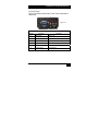
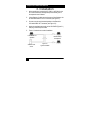
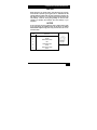
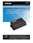
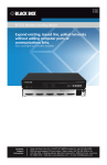
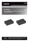
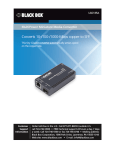
AC155A-R3
UMA1088 Rev B
Compact CAT5 Audio/Video Receiver
Converts the CAT5 signals sent from the AC154A-2
or AC154A-8 splitter back to standard VGA video
and audio for connection to a standard VGA monitor
and PC speakers.
TRADEMARKS USED IN THIS MANUAL
Compact CAT5 Audio/Video Receiver
BLACK BOX and its logo
Technologies, Inc.
are registered trademarks of BB
Apple and Macintosh are registered trademarks of Apple Computer, Inc.
Belden Brilliance® is a registered trademark and VideoTwist™ is a
trademark of Belden Technologies, Inc.
IBM is a registered trademark of International Business Machines
Corporation.
SGI is a registered trademark of Silicon Graphics, Inc.
Sun and Sun Microsystems are registered trademarks of Sun
Microsystems, Inc. in the United States and other countries.
Any other trademarks mentioned in this manual are acknowledged to be
the property of the trademark owners.
11
Compact CAT5 Audio/Video Receiver
FEDERAL COMMUNICATIONS COMMISSION AND
INDUSTRY CANADA RADIO FREQUENCY
INTERFERENCE STATEMENTS
This equipment generates, uses, and can radiate radio-frequency energy, and if not
installed and used properly, that is, in strict accordance with the manufacturer’s
instructions, may cause interference to radio communication. It has been tested and
found to comply with the limits for a Class A computing device in accordance with the
specifications in Subpart J of Part 15 of FCC rules, which are designed to provide
reasonable protection against such interference when the equipment is operated in a
commercial environment. Operation of this equipment in a residential area is likely to
cause interference, in which case the user; at own expense; will be required to take
whatever measures may be necessary to correct the interference.
Changes or modifications not expressly approved by the party responsible for
compliance could void the user’s authority to operate the equipment. This digital
apparatus does not exceed the Class A limits for radio noise emission from digital
apparatus set out in the Radio Interference Regulation of Industry Canada
.
Le présent appareil numérique n’émet pas de bruits radioélectriques dépassant les
limites applicables aux appareils numériques de classe A prescrites dans le
Règlement sur le brouillage radioélectrique publié par Industrie Canada.
22
Compact CAT5 Audio/Video Receiver
Normas Oficiales Mexicanas (NOM) Electrical Safety
Statement
INSTRUCCIONES DE SEGURIDAD
1.
2.
3.
4.
5.
6.
7.
8.
9.
10.
11.
12.
Todas las instrucciones de seguridad y operación deberán ser leídas
antes de que el aparato eléctrico sea operado.
Las instrucciones de seguridad y operación deberán ser guardadas para
referencia futura.
Todas las advertencias en el aparato eléctrico y en sus instrucciones de
operación deben ser respetadas.
Todas las instrucciones de operación y uso deben ser seguidas.
El aparato eléctrico no deberá ser usado cerca del agua—por ejemplo,
cerca de la tina de baño, lavabo, sótano mojado o cerca de una alberca,
etc.
El aparato eléctrico debe ser usado únicamente con carritos o pedestales
que sean recomendados por el fabricante.
El aparato eléctrico debe ser montado a la pared o al techo sólo como
sea recomendado por el fabricante.
Servicio—El usuario no debe intentar dar servicio al equipo eléctrico más
allá a lo descrito en las instrucciones de operación. Todo otro servicio
deberá ser referido a personal de servicio calificado.
El aparato eléctrico debe ser situado de tal manera que su posición no
interfiera su uso. La colocación del aparato eléctrico sobre una cama,
sofá, alfombra o superficie similar puede bloquea la ventilación, no se
debe colocar en libreros o gabinetes que impidan el flujo de aire por los
orificios de ventilación.
El equipo eléctrico deber ser situado fuera del alcance de fuentes de calor
como radiadores, registros de calor, estufas u otros aparatos (incluyendo
amplificadores) que producen calor.
El aparato eléctrico deberá ser connectado a una fuente de poder sólo del
tipo descrito en el instructivo de operación, o como se indique en el
aparato.
Precaución debe ser tomada de tal manera que la tierra fisica y la
polarización del equipo no sea eliminada.
33
Compact CAT5 Audio/Video Receiver
13.
14.
15.
16.
17.
18.
44
Los cables de la fuente de poder deben ser guiados de tal manera que no
sean pisados ni pellizcados por objetos colocados sobre o contra ellos,
poniendo particular atención a los contactos y receptáculos donde salen
del aparato.
El equipo eléctrico debe ser limpiado únicamente de acuerdo a las
recomendaciones del fabricante.
En caso de existir, una antena externa deberá ser localizada lejos de las
lineas de energia.
El cable de corriente deberá ser desconectado del cuando el equipo no
sea usado por un largo periodo de tiempo.
Cuidado debe ser tomado de tal manera que objectos liquidos no sean
derramados sobre la cubierta u orificios de ventilación.
Servicio por personal calificado deberá ser provisto cuando:
a.
El cable de poder o el contacto ha sido dañado; u
b.
Objectos han caído o líquido ha sido derramado dentro del
aparato; o
c.
El aparato ha sido expuesto a la lluvia; o
d.
El aparato parece no operar normalmente o muestra un
cambio en su desempeño; o
e.
El aparato ha sido tirado o su cubierta ha sido dañada.
Compact CAT5 Audio/Video Receiver
Contents
1. SPECIFICATIONS .........................................................................6
VIDEO ................................................................................................6
AUDIO ................................................................................................6
GENERAL ..........................................................................................6
2. OVERVIEW ....................................................................................7
2.1 INTRODUCTION ...........................................................................7
2.2 FEATURES ..................................................................................7
2.3 WHAT’S INCLUDED ......................................................................8
2.4 HARDWARE DESCRIPTION ...........................................................8
3. INSTALLATION ...........................................................................10
4. CONFIGURATION & OPERATION .............................................13
4.1 WHY CABLE COMPENSATION?...................................................13
4.2 COMPENSATION ADJUSTMENT PROCEDURE ...............................14
4.3 ADVANCED ADJUSTMENT (CATX AWG).....................................15
5. TROUBLESHOOTING .................................................................16
5.1 PROBLEMS/SOLUTIONS .............................................................16
5.2 CALLING BLACK BOX.................................................................18
5.3 SHIPPING AND PACKAGING ........................................................18
55
Compact CAT5 Audio/Video Receiver
1. Specifications
Video
Gain
Impedance
Maximum resolution
Nominal amplitude
Unity
75 ohms
Up to 1920x1200 and 1080p at 750 ft (234.4 m); 1280x1024 at 850 ft. (386.4)
1 V p-p for Y of component video
0.7 V p-p for RGB and for Pr and Pb of component video
4.0 V to 5.0 V p-p, for TTL Sync signals of RGBHV, RGBS
Number/signal type 1 proprietary analog signal input. Standard VGA output RGBHV, RGBS, RGsB, RsGsBs,
component video (bi-/tri-level sync)
Polarity
Positive or negative
Connectors
1 female RJ-45 input, 1 HD15 output
Audio
Frequency
response
Gain
THD + Noise
Type
Connector
20 Hz to 20 kHz, ±1 dB
Unbalanced output: 0 dB
0.2% @ 1 kHz, 0.3% @ 20 kHz at nominal level
Monaural, Simulated Stereo
(1) 3.5 mm connector
General
Compliance
Cooling
Enclosure type
Mounting
Recommended cable
Vibration
Temperature/humidity
Humidity
MTBF
Power
Dimensions
Product weight
Shipping weight
66
CE, FCC Part 15 Subpart J Class A, IC Class
Convection, vents on each end
Metal
Brackets at each end with screw hole provided for Wall or Rack mounting
CAT 5/5e/6 (shielded or unshielded)
ISTA 1A in carton (International Safe Transit Association)
Operating: +32 to +122 °F (0 to +50 °C); Storage: -40 to +158 °F (-40 to +70 °C)
10% to 90%, non-condensing
90,000 hours
100 VAC to 240 VAC, 50-60 Hz, external; 5 VDC, 2 A, regulated; 2.1mm
1.18" H x 2.75" W x 3.85" D (3 cm H x 7 cm W x 9.8 cm D)
0.75 lb (0.35 kg)
1.5 lbs (0.70 kg)
Compact CAT5 Audio/Video Receiver
2. Overview
2.1 Introduction
• The Compact CAT5 Audio/Video Receiver (AC155A-R3) is
designed to be used with the AC154A-2 and AC154A-8
Splitters. It converts the CAT5 signals sent from the Splitter
back to standard VGA video and audio for connection to
standard VGA monitor and PC speakers.
• The device is housed in a compact shielded enclosure and
includes a HD15 connector for the monitor, 3.5mm mini-stereo
audio connector for the speakers, and one RJ45 connector for
the CAT5 cable input. A small universal power supply is
included with the AC155A-R3.
• The AC155A-R3 can recover the VGA and audio signals from
UTP or STP (CAT5/5e/6) cables up to 1000 feet (300 meters)
long with little to no degradation. The Receiver features a
proprietary circuit to allow the user to compensate for signal
losses in long cable runs.
2.2 Features
•
•
•
•
•
Supports resolutions up to 1920x1440 at 60 Hz
Adjustable cable length compensation to 1000 ft
Rugged, reliable and compact size
No software required for setup and use
Receives audio and video on a single CATx cable
77
Compact CAT5 Audio/Video Receiver
2.3 What’s Included
•
•
•
•
Compact CAT5 Audio/Video Receiver
This user’s manual
Power Supply
Power Supply Cord
2.4 Hardware Description
2.4.1 Side 1 Panel
Figure 2.1 shows the receivers Side 1 Panel. Table 2-1 describes its
components.
Figure 2.1
↑
↑
↑
↑
1
2
3
4
TABLE 2-1
Number
88
Component
Description
1
Power Connector
Power Input
2
Power LED
Illuminates when power applied
3
3.5 mm Connector
Audio Out
4
RJ-45 Connector
UTP Input
Compact CAT5 Audio/Video Receiver
2.4.2 Side 2 Panel
Figure 2.2 shows the receivers Side 1 Panel. Table 2-2 describes its
components.
5
6
7
↓ ↓ ↓
Figure 2.2
↑
8
↑
↑
9
10
TABLE 2-2
Number
Component
Description
5
LED Indicator
SELECT LED
6
LED Indicator
DOWN LED
7
LED Indicator
UP LED
8
HD15 Connector
VGA Output
9
Push button
SELECT Button
10
(2) Push buttons
Down/Up Buttons
99
Compact CAT5 Audio/Video Receiver
3. Installation
1.
At the sending end, connect the AC 154A-2 or AC154A-8 to the
CPU and local monitor and keyboard per instructions given in
the respective user’s Manual.
2.
Using Category-5 cable, connect the output of the Splitter to the
AC155A-R3 Receiver’s UTP IN connector (see Figure 2.1)
3.
Connect a monitor and powered speakers to the Receiver’s
VGA and AUDIO OUT connectors (see Figure 2.2).
4.
Attach the supplied power supply to the AC155A-R3 (Figure 2.1)
and plug it in the AC power outlet.
5.
Figure 3.1 below shows a typical installation
Local Monitor and
Speakers
VGA and Audio
Source
10
10
Remote Monitor
and Speakers
Figure 3.1
Typical Installation
Compact CAT5 Audio/Video Receiver
CAUTION
Before plugging in your remote monitor, verify that the AC line is properly
wired and that a protective ground (green) wire is established with NO
potential difference between both the sender and Receiver locations (The
UTP Splitter can tolerate up to 5 v peak-to-peak ground noise between the
two locations) . Failure to ensure good grounding can result in erratic
operation and possible shock hazards with severe damage to your
equipment.
NOTICE
Do not connect this unit to any LAN device such as network cards or hubs
as this may damage the AC155A-R3 and/or the LAN device. Use EIA/TIA
568B standard straight-through patch wiring as shown below. Do not use
crossover cables.
PIN
1
2
3
4
5
6
7
8
EIA/TIA 568B WIRING STANDARD
Wire Color
White w/ Orange Stripe
Orange
White w/Green Stripe
Blue
White w/Blue Stripe
Green
White w/Brown Stripe
Brown
11
11
Compact CAT5 Audio/Video Receiver
Tips on Cable Selection for Best Image Quality
The AC155A-R3 compensates for high frequency losses in the cable. However,
due to the twist ratio differences in the UTP cable, it is recommended to use UTP
cables that are specifically designed for video transmission. These cables are
commonly referred to as zero or low skew cables.
Example: Belden Brilliance® VideoTwist™ 7987R/P.
If you don’t have access to this type of cable, we recommend using CAT5 (or
CAT5e) cable rather than CAT6 since CAT5 cables have better twist ratio match
than CAT6 does.
12
12
Compact CAT5 Audio/Video Receiver
4. Configuration &
Operation
4.1 Why Cable Compensation?
Resolution
All cables attenuate (reduce) the high-frequency components of the
video signal that is being transmitted. The longer the cable, the more
signal loss. If not compensated for, this signal loss will result in blurry
and smeared images being displayed.
The image quality depends on the resolution and level of detail in the
image. The Compact CAT5 Audio/Video Receiver has one of the
most precise and complex equalization techniques in the industry
and allows for full recovery of the original signal’s bandwidth.
Make this adjustment using a test pattern that is designed to depict
and exaggerate this effect. Connect a PC to the video input and
display a test pattern.
The table below lists the recommended maximum distances from
sender to the receiver depending on the resolution used.
640x480
800x600
1024x768
1280x1024
1600x1200
60 Hz
1,000 ft
1,000 ft
1,000 ft
750 ft
750 ft
Refresh Rate
75 Hz
1,000 ft
1,000 ft
800 ft
600 ft
600 ft
85 Hz
1,000 ft
1,000 ft
700 ft
525 ft
525 ft
Table 4-1
Recommended maximum CATx cable length from sender to the receiver
13
13
Compact CAT5 Audio/Video Receiver
4.2 Compensation Adjustment Procedure
• Press the SELECT button once to enter the adjustment-mode
(that is, without first hitting SELECT button the up and down
arrows are inactive).
• In adjustment-mode, all 3 LEDs on the unit will be turned on.
• The UP or DOWN buttons can now be used to adjust the high
frequency (HF) compensation up or down until the video no
longer looks smeared (see figure 4-1 & 4.2 below).
• Pressing both the UP & DOWN buttons together resets the
current adjustment back to zero. This is a quick way to start
over.
• To exit the adjustment mode at any time, press the SELECT
button (the unit also has a built-in timeout to exit this mode).
Figure 4.1 - Typical test patterns used for adjusting compensation
14
14
Compact CAT5 Audio/Video Receiver
Figure 4.2 – Effect of adjustment on the smearing
4.3 Advanced Adjustment (CATx AWG)
The AC155A-R3 automatically equalizes the brightness of the
video as the smearing is reduced. This automatic adjustment is
based on the assumption that typical 24 AWG CATx cable is
being used. When using 23 AWG CATx cable, then when the
smearing is minimized, your image may be brighter than normal.
In many installations, this is not critical and usually requires no
adjustment. There is a setting for the cable type (23 vs. 24
AWG) that can be changed for different performance.
•
•
•
While in the adjustment-mode, press and hold the SELECT
button for at least 3 seconds to enable the WIRE SIZE
selection mode between 23-gauge wire and 24-gauge wire.
The UP button is used to select 24-gauge wire. The DOWN
button is used to select 23-gauge wire.
To exit the adjustment mode at any time, press the
SELECT button (the unit also has a built-in timeout to exit
this mode).
15
15
Compact CAT5 Audio/Video Receiver
5. Troubleshooting
5.1 Problems/Solutions
Problem: Fuzzy, blurry, or ghosting image at remote location
Solution: If you have a stable image but it looks somewhat blurry
(e.g. the edges are not sharp), make sure that you have adjusted the
receiver unit’s HF compensation correctly. In addition, check the
recommended table of max distances vs. resolution and ensure that
you have not exceeded the maximum recommended cable lengths. If
you still have a fuzzy image, try reducing the refresh rate and/or
resolution of the video source.
Problem: Image exhibits steady or rolling horizontal color “hum” bars
Solution: This is usually an indication of improper grounding either
at the sending end, the receiving end, or both. Verify that the AC line
is properly wired and that a protective ground (green) wire is
established with NO potential difference between both the sender
and Receiver locations. The UTP Splitter can tolerate up to 5 v peakto-peak of ground noise between the two locations, but no more.
16
16
Compact CAT5 Audio/Video Receiver
Problem: Shaking image or periodically blanking monitor
Solution: Although CAT5 cable uses twisted pairs to transmit the
signals from the Splitter to the Receivers to reduce the amount of
EMI coupled noise from other external sources, a strong
electromagnetic noise field can cause instability in the signal.
Usual sources of this form of noise coupling are high current AC lines
or other high-density data and/or control cables that run adjacent to
and parallel with a substantial length of the CAT5 cable. To eliminate
this, either place a distance between the CAT5 cables from the
Splitter and the interfering source, or use STP shielded CAT5 cables.
Problem: The PC does not recognize a Plug-and-Play monitor
Solution: If the PC’s Operating System is setup to detect a plug-andplay monitor (usually in Display Properties Advanced Settings), it
may have trouble finding a monitor if no local monitor is hooked up to
the Splitter (at the sending end). Only the ID information of the local
monitor is passed to the PC. If the PC does not produce an image
due to this, either connect a monitor to the local VGA output port, or
disable the plug-and-play monitor detection in the PC’s operating
system.
Problem: Faint shadows or ghosts at the remote monitor
Solution: The Splitter at the sending end has multiple RJ45 output
connectors. When a long CAT5 cable is plugged in any of the
outputs, the Splitter expects a Receiver at the other end for proper
termination. Therefore it is a good idea to unplug the un-terminated
CAT5 cables from the Splitter unit. Please refer to item 1 above for
other possible causes.
17
17
Compact CAT5 Audio/Video Receiver
Problem: Poor audio quality at the Receiver
Solution: Only use powered speakers with the Receiver. It is also
good practice to set the audio level (volume) output of the PC about
1/2 to 2/3 from the maximum and use the volume knob of the
speakers to adjust the volume to the desired level. A low volume
signal output from the PC reduces the signal-to-noise (S/N) ratio,
whereas too high output amplitude can cause saturation and clipping
to occur.
5.2 Calling Black Box
If you determine that your Receiver is malfunctioning, do not attempt
to repair the unit. Contact Black Box Tech. Support at 724-746-5500
or [email protected]
Before you do, make a record of the history of the problem. We will
be able to provide more efficient and accurate assistance if you have
a complete description.
5.3 Shipping and Packaging
If you need to transport or ship your Receiver:
• Package it carefully. We recommend that you use the original
container.
• Before you ship the unit back to Black Box for repair or return,
contact us to get a Return Authorization (RA) number.
18
18
Black Box Tech Support: FREE! Live. 24/7.
Tech support the
way it should be.
Great tech support is just 20 seconds away
at 724-746-5500 or blackbox.com
About Black Box
Black Box Network Services is your source for more than 118,000
networking and infrastructure products. You’ll find everything from
cabinets and racks and power and surge protection to media
converters and Ethernet switches all supported by free, live 24/7 Tech
support available in 20 seconds or less.
© Copyright 2010. All rights reserved
19