1
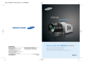
LDT-05
Digital electronic theodolite
User Manual
Content
1. Use and Scope of Application of the instrument
2. Main Technical Parameters
3. Structure
4. Function of Buttons
5. Preparation before Measurement
5.1 Preparation of Battery
5.2 Set-up of the Instrument
5.3 Leveling of the Instrument
5.4 Centering
5.5 Collimation
5.6 Initial Setting
6. Operation Method
6.1 Start Up
6.2 Measurement of Angles
6.3 Turning Off
6.4 Measuring Distance Using the Stadia Method
6.5 Installation and Removal of Base
7. Inspection and Adjustment
7.1 Tubular vial
7.2 Circular vial
7.3 Laser Plummet
7.4 Perpendicularity of Vertical Hair of Reticle of Telescope
7.5 Collimation error
7.6 Index Error of Vertical Circle
8. Accessories
9. Error Information
1
Cautions
•
Carefully read and understand this manual before use.
•
Do not directly aim the telescope to the sun to avoid injury to your eyes.
•
Do not loosen or remove any screw(s) of the instrument.
•
Protect the instrument from hard shocks.
•
Do not carry the instrument mounted on a tripod on your shoulder.
•
Do not expose the instrument under the sun for long periods of time and
keep away from heat source to avoid damage.
•
Sudden changes of temperature will influence the precision of measurement and the normal operation of the electronic system and may cause
fogging on the object lens. When the instrument is taken from the cold
weather outdoors to indoors, it must be placed in a warm place to allow
any fog to evaporate.
•
This instrument contains many sensitive electronic components and is provided with protection against dust and moisture. If dust or moisture enters
into the instrument damage to the instrument may result. Therefore, after
using in a humid environment, the instrument must be dried immediately
and stored in the instrument case.
•
The display of LCD system will be affected in operation under low temperatures. It is recommended to start the instrument in advance before
operation.
•
The battery must be removed from the instrument if it is to be out of
service for a long time.
•
Before placing the instrument into
the instrument case, align the dot
mark of the instrument up ward
and on the same line, and lightly
tighten the clamp knobs then loosen after the instrument is placed in
the case. All the clamp knobs must
be slightly tightened again after the
instrument is in place in the case
for transport.
2
1. Use and Scope of Application of the Instrument
This series of electronic theodolite adopts the photoelectric incremental angle
measuring system. They integrate optical, mechanical, electronic and computer
technologies all in one, realizing a variety of functions including angle measurement, display and storage. They can also display horizontal and vertical angles
and realize conversion from vertical angle to gradient and compensation of
vertical angle. The precision of angle measurement is 5”.
This series of electronic theodolite adapts to wide applications in the Grade III
and Grade IV triangle control measurement in national and urban projects, including engineering measurement in railway, highway, bridge, water conservancy, mining projects, etc. It can be also used in various engineering, construction,
and topographic surveys.
3
2. Main Technical Parameters
Telescope
Angle
Measurement
System
Compensator
Optical
Plummet
Vial sensitivity
Image
Erect
Magnification
30x
Objective aperture
45mm
Field of view
1°30’
Shortest visibility distance
1.35m
Stadia multiplying constant
100
Stadia additive constant
0
Resolution
3”
Mode of angle measurement
Photoelectric incremental reading
Minimum reading
1” 5”
Detection method
H: both sides; V: single side
Precision of angle measurement
5”
Angle unit
DEG MIL GON
Display
LCD double sides
Tilt sensor
Yes - vertical
Compensator range
± 3’
Image
Erect
Magnification ratio
3x
Angle of View
5°
Focusing range
0.5m~ ∞
Tubular vial
30” /2mm
Circular vial
8’ /2mm
Ambient temperature range
Power
-20°C ~ +50°C
Battery
Alkaline battery, rechargeable Ni-H
battery
Source voltage
4.8V
Duration of operation
Alkaline battery 36h
Weight
4.6kg
Dimensions
164 x 154 x 340mm
4
3. Structure
S28-6015
Screw of handle
S28-3012
Handle
S28-1201
Objective lens
S28-1104
Horizontal
clamp screw
S28-1109
LCD Display 1
S28-1106
Laser plummet
S5-4-1103
Leveling screw
S5-3004
Tribach
locking lever
5
3. Structure (part 2)
S28-6045
Focusing knob
S28-1205
Eyepiece
S28-1103
S28-1107
Collimator
S28-1105
Telescope
clamp screw
S28-1112
LCD display II
S28-1107
Tubular vial
1217
Circular vial
6
4. Function of Buttons
Button
Function 1
Other
1.One of the functions for entering
into initial setting of the instrument.
ON/OFF
ON/OFF power for the instrument
2.One of the function buttons for
entering into index error setting.
3.One of the function buttons for
entering into compensation setting.
Button for illumination of Reticle and LCD Display
1.Menu selection button in initial
setting.
OSET
r
Reset of horizontal angle
(zeroing)
2.One of the function buttons for
entering into Compensator setting.
3.One of the function buttons for
entering into initial setting of the
instrument.
1.Menu selection button in initial
setting.
HOLD
w
Horizontal angle hold button
2.One of the function buttons for
entering into initial setting of the
instrument.
3.One of the function buttons for
entering into index error setting.
R/L
v
V%
Increment of left rotation and
right rotation of horizontal angle
Vertical angle and slope convert
1.Menu selection button in initial
setting.
2.One of the function buttons for
entering into initial setting of the
instrument.
1.One of the function buttons for
entering into initial setting of the
instrument.
2.Button for confirmation after initial
setting of the instrument.
7
5. Preparation before Measurement
5.1 Preparation of Battery
5.1.1
Checking the Electric Quantity of Battery Case Refer to 6.1.3
5.1.2
Removal of Battery Case
1.Turn the knob of the battery case and let the mark q point to
“UNLOCK”, take the battery case off. (as shown in Fig.5-1).
2.Open the case cover, insert four AA batteries into the battery
case according to (+) and (-).
3.Insert the raised part at the bottom of the battery case into
the slot of the right battery cover, and put the battery case in
place. Then turn the knob and let the mark q point to “LOCK”
(as shown in Fig. 5-2).
Fig 5-1
8
Fig 5-2
5. Preparation before Measurement
5.1.3
Recharging the Battery
1.Remove the charger from the instrument case and connect
the charger to AC 110V power source. The green light on the
charger is lit.
2.Insert the charger plug into the charging port of the battery
case. The green light of the charger turns red, the charging
process is started. After 3–4 hours when the red light turns
green, it indicates that the charging process is complete.
ATTENTION
• The four batteries in the battery case should be of the same brand-type.
• Do not use batteries which have different remaining capacities.
• When batteries are wet, dry them immediately, and take them out of the
instrument case, air-dry thoroughly.
• When the battery case is removed from the unit, power must be off to avoid
damage or problems.
9
5. Preparation before Measurement
5.2 Set-up of the Instrument
5.2.1
Extend the tripod to the desired height .
5.2.2
Ensure that the measure point is exactly under the central hole of the tripod head.
5.2.3
Level up the tripod (this is very important when centering with plumb bob).
5.2.4
Ensure that all locking handles are securely tightened.
5.2.5
Secure the instrument to the tripod.
5.3 Leveling up of the Instrument
Centering the circle vial using leveling screws A, B and C. (Presume that the three leveling screws be A, B and C).
5.3.2
Turn the collimation unit so that the axis of the tubular vial is parallel to the connecting line of B and C. adjust B and C so that the tubular vial is centered (as shown in 1. of Fig. 5-3).
5.3.3
Turn the collimation 90°, adjust the leveling screw A and center the bubble.
5.3.4
Repeat 5.3.2–5.3.3, until the bubble is the centered when
observed from both directions.
1
2
A
B
A
C
A
Fig 5-3
10
B
A
A
5.3.1
C
5. Preparation before Measurement
5.3.5
After 5.3.2 is complete, turn collimation unit 180°. If the tubular
vial is still centered, the leveling up of the instrument is complete. If the bubble strays from the center, perform leveling up with the procedure for adjustment of tubular vial in “Inspection and
Adjustment”.
5.4 Centering
5.4.1
Centering with Plumb Bob
1.Tie the plumb bob wire to the hook on the central screw. Adjust the length of the wire so that the tip of the bob is (1/8”)
2mm above ground.
2.Loosen the central screw and move the base so that the tip
of the plumb bob is precisely positioned to the ground point
(when observed from two directions perpendicular to each
other).
Centering with Laser plummet
5.4.2
To ensure maximum measuring precision, we recommend the
performance of the steps described in “Inspection and
Adjustment” before using this instrument.
1.View the laser beam in relation to the desired target point.
Loosen the central screw to translate the whole instrument (be
sure not to turn the instrument) so that the ground point coincides with the central point of the laser. Retighten the central
screw.
2.Perform precise leveling up of the instrument as described
in 5.3 and repeat the operation in (1) of 5.4.2 until the
instrument is precisely leveled up and the center of the laser
precisely coincides with the ground point (as shown in Fig.5-4).
1
2
Ground point
Fig. 5-4
11
5. Preparation before Measurement
5.5 Collimation
5.5.1
Adjustment of diopter
Direct the telescope to a bright background. Turn the eyepiece knob so that the cross hairs of the reticle are clearly seen.
Elimination of Optical Parallax
5.5.2
Adjust the focusing knob so that the object forms an image on
the reticle. Move your eyes up and down to see if the image of
the object moves relative to the graduation lines. If it does not
move, there is no optical parallax; otherwise turn the focusing
knob to eliminate the optical parallax.
5.6 Initial Settings
Before you start measuring, please confirm all initial settings. Items in bold indicate factory settings.
Initial Setting
Selection
1. Unit of Angle
360°
UNIT A
2. Zenith Angle
ZEN = = 0
ZEN = = 90
3. Auto Power Off Time
30 OFF
NO OFF
4. Min. Display
DSPl
DSP5
5. Compensator Switch
V TILT ON
V T1LT OFF
6. Indication of Position of Horizontal Angle
NO BEEP
90 BEEP
5.6.1
12
400G
UNIT B
6400
UNIT C
Method of Setting
Press and hold [HOLD] button + [OSET] button and press [ON/
OFF] button. Release [ON/OFF] button when full character display
appears and release [HOLD] + [OSET] buttons when four beeps
are heard. The instrument enters into initial setting mode and the
LCD displays:
5. Preparation before Measurement
V 360° ‘ “
UNITA
1.Press [w] button or [v] button for turning pages and selecting
options.
2.Press [r] button for selecting specific content in the options.
3.Finally, press [V / %] button to confirm and enter into angle
measuring mode.
Setting of Items
5.6.2
1.Unit of Angle
UNIT A: 360° (Degree)
UNIT C: 6400 (Mil)
2.Zero Position of Vertical Angle
ZEN = = 0: Zenith being 0°
ZEN = = 90: Zenith being 90°
a
UNIT B: 400 (GON)
V 360° ‘ “
UNITA
ZEN==90
VERTICAL
a
3.Auto Power off Time
NO OFF: Auto power off disabled
4.Minimum Display
DSP 1: minimum display being 1”
a
30 OFF: Turns power off if no
action within 30min
NO OFF
AUTO OFF
DSP 1
DSP 5: minimum display being 5”
DSP 10: minimum display being 10”
13
5. Preparation before Measurement
a
5.Setting of compensator
V TILT ON: Turn on the compensator
TILT ON
V TILT OFF: Turn off the compensator
a
6.Indication of Horizontal Angle
NO BEEP: Horizontal angle
indication disabled
90 BEEP: Beeps when the instrument
is close to 0°, 90°, 180° and 270°.
14
ON BEEP
6. Operation Method
6.1 Start Up
6.1.1
Press and hold [ON/OFF] button. Release [ON/OFF] button when
the full character display appears. The LCD displays:
V
H
R
SETO
150°36‘10“
6.1.2
Sway the telescope up and down ward when the instrument is in
the normal position. A beep occurs and the LCD displays vertical
angle. The instrument enters into measuring mode.
6.1.3
After the power is switched on and the instrument has entered
into measuring mode, the battery energy consumption is indicated
by the battery symbol in the lower right corner of LCD.
1.If all of the three cubes are displayed, it indicates that the battery is fully
2.Decreasing of the cubes indicates the reduction of charge.
3.If the battery symbol twinkles, it indicates a low battery and
recharging is required.
V
H
R
86°28‘48“
150°36‘10“
the battery symbol
6.2 Measurement of Angles
• Observing in the “Normal” and “Reverse” Positions of the Telescope
The normal position of the telescope refers to observation with the object
lens facing right ahead (the vertical encoder being on the left); the reverse
position refers to observation with the object lens facing right ahead (the
vertical encoder being on the right). The mechanical errors can be offset
by the average of the values of measured in the normal and reverse positions.
15
6. Operation Method
6.2.1
Measurement of Vertical Angle
1.Measurement of 0° angle of vertical angle
0° angle position can be set as follows in the initial setting:
ZEN == 90° (Zenith 90°)
ZEN == 0° (Zenith 0°)
90°
0°
90°
0°
270°
180°
270°
180°
Fig. 6-2
2.Compensation of the tilt sensor to
Vertical Angle
V
H
RL
3.Display of slope
Note: When vertical angle is
turned into slope, the precision
of slope is to the fourth digit
after the decimal.
16
V
H
RL
69°11‘00“
108°36‘38“
a
Press [V/%] button, the vertical
angle display is turned into a slope
display; press [V/%] button, the
vertical angle display is resumed.
TILT
108°36‘38“
a
If the inclination is greater than
±3’, the instrument will display as
shown in the figure.
90°00‘10“
108°36‘38“
a
If the instrument is inclined within
±3’, the tilt sensor compensates to
the vertical angle.
V
H
RL
V
H
RL
38.88%
108°36‘38“
6. Operation Method
6.2.2
Measurement of Horizontal Angle
1.Reset of Horizontal Angle
V
H
RL
V
H
RL
V
H
RL
2.Selecting the Direction of
Measurement of Horizontal Angle
When “HR” is displayed, the angle
increases with clockwise turning of
the collimation unit.
90°00‘10“
150°36‘10“
V
H
RL
90°00‘10“
00°00‘00“
90°00‘10“
150°36‘10“
a
Press [R/L] button to change the
direction of measurement of the
horizontal angle.
69°11‘00“
150°36‘10“
a
Press [OSET] button, the horizontal angle returns to zero.
a
The value of slope is effective
within ± 45°; there will be no
slope display exceeding this range.
V
H
RL
90°00‘10“
199°23‘50“
When “HL” is displayed, the angle
increases with counter-clockwise
turning of the collimation unit.
17
6. Operation Method
3.Holding Horizontal Angle
6.3 Turning Off
Press [ON/OFF] button, “OFF” will be displayed
at the position of vertical angle display after
a beep; release [ON/OFF] button, the
instrument is turned off.
V
H
RL
90°00‘10“
150°36‘10“
a
Press [HOLD] button, the horizontal
angle will be held; the reading of
the horizontal angle will remain
unchanged even if the direction of
collimation is changed. Press
[HOLD] button again, the hold of
horizontal angle is released.
V
H
RL
V
H
RL
90°00‘10“
150°36‘10“
OFF
150°36‘10“
6.4 Measuring Distance Using the Stadia Method
Take reading l from the staff gauge using the stadia hair on the reticle of the
telescope. Multiply reading l by 100, we obtain the actual distance L from the
target to the measured point. (100 is the multiplication constant error of the
instrument, i.e., L = 1×100)
L
Fig. 6-3
18
Fig. 6-4
6. Operation Method
6.5 Installation and Removal of the Base
6.5.1
Remove of the Base
1.Turn the screw on knob S5-3004 outward using flat screw
driver until it no more limits position.
2.Turn knob S5-3004 180° counter-clockwise, holding the base
with one hand and take the main body of the instrument off
the base (as shown in Fig.6-5).
Installation of the Base
6.5.2
1.Turn the knob S5-3004 counter-clockwise until it reaches the
position limit ‘ . Make the positioning block S3-4001 on the
main body of the instrument is in line with the notch on the
base and install the main body onto the base (as shown in
Fig.6-6).
2.Turn the knob S5-3004 clockwise until it reaches the position
limit so that the r mark points downward. Turn the screw until
it can limit position.
S3-4001
Positioning
Block
Notch
S5-3004 knob
Fig. 6-5
Fig. 6-6
19
7. Inspection and Adjustment
7.1 Tubular vial
7.1.1
Inspection
1.Fix the instrument to the tripod and roughly level up the instrument and make the tubular vial parallel to the connecting line
of two of the three leveling screws on the base. Adjust the two
leveling screws so that the tubular vial is centered.
2.Turn the instrument 180° and check if the bubble remains
centered.
3.If the bubble remains centered, no adjustment is required;
otherwise, perform adjustment as follows.
Adjustment
7.1.2
1.Adjust the bubble adjusting screw so that the bubble moves
toward tube center for half the off-center value (as shown in
Fig.7-1)
Fig. 7-1
2.Turn the leveling screw to correct the other half off-center so
that the bubble stays centered.
3.Repeat steps in 7.1.1 and 7.1.2 until the long level is centered
when the instrument is at any position.
20
7. Inspection and Adjustment
7.2 Circle vial
After making sure that the long level is correctly adjusted, check if there
is any off-center with the round level. If it is centered, no adjustment is
required; otherwise, adjust the three adjustment screws with needle as
shown in Fig.7-2 to center the bubble.
Fig. 7-2
7.3 Optical Plummet – Not applicable to LDT-05 units with laser plummet
7.3.1
Inspection
1.Set the instrument on the tripod (no adjustment is required).
2.Place the cross mark exactly under the instrument.
3.Adjust the image of the object so that is in focus. Using the
optical plummet, adjust the leveling screws so that the cross
mark moves to the center of the reticle.
4.Turn the instrument for 180°.
5.If the cross mark remains at the center of the reticle, no adjustment is required; otherwise, adjust as follows.
21
7. Inspection and Adjustment
7.3.2
Adjustment
Adjust the adjustment screw of the reticle,using the needle, so
that the cross mark moves to halfway of the off-center (as shown
in Fig.7-3 and Fig.7-4).
Repeat the steps 3–5 in 7.3.1 and step 1 in 7.3.2 until the cross
mark coincides with the center.
Fig. 7-3
Half-distance
Fig. 7-4
7.4 Perpendicularity of Vertical Hair of Reticle of Telescope
7.4.1
Inspection
1.Fix the instrument on the tripod and perform precise leveling
up.
2.Set an target point A 50m away from instrument.
Aim the telescope at target point A and adjust the vertical
fine movement. If point A moves along the vertical hair of the
reticle, no adjustment is required; perform adjustment if the
target point A strays from the vertical hair.
7.4.2
Adjustment
1.Remove the protective cover of the reticle and slightly loosen
the four adjusting screws. Turn the assembly so that point A
coincides with the vertical hair. Retighten the four adjusting
screws.
Repeat step 3 in 7.4.1 and step 1 in 7.4.2 until there is no
error.
22
7. Inspection and Adjustment
A
A
A
A
Fig. 7-5
7.5 Collimation Discrepancy
7.5.1
Inspection
1.Fix the instrument on the tripod and perform precise leveling
up.
2.Aim at object point A in the distance with the normal position of telescope and take the reading of the horizontal angle
HRnorm. and aim at object A with the reverse position of the
telescope and take the reading of the horizontal angle HRrev
then:
Collimation Error C = (HRnorm - HRrev ± 180°) / 2
If C <10”, no adjustment is required; if C >10”, adjustment is
required.
7.5.2
Adjustment
1.Adjust the horizontal fine motion in the reverse position of the
telescope so that the reverse reading HRrev’ = HRrev + C.
2.Remove the protective cover of the reticle of the telescope and
adjust both the left and right adjusting screws so that the vertical hair of the reticle coincides with object A.
Repeat the steps in 7.5.1 and 7.5.2 until acceptable condition is reached.
23
7. Inspection and Adjustment
7.6 Index Error of Vertical Circle
7.6.1
Inspection
1.Fix the instrument on the tripod and perform precise leveling
up.
2.Aim the telescope at any object point P in the normal position
and take the reading of vertical angle Vnorm.
3.Turn the telescope to the reverse position and aim it at point P
again. Take the reading of other vertical angle VRev.
If (Vnorm + VRev) - 360° = 2I, I ≤ 15”, no adjustment is
required; otherwise, perform adjustment as follows:
7.6.2
1.Press and hold [R/L] + [HOLD]
buttons and press [ON/OFF]
button. Release [ON/OFF] button
when full character display appears
and release [R/L] + [HOLD] buttons
when four beeps are heard.
Aim the telescope in the normal
position at object P and press
[OSET] to confirm.
V
H
R
V
H
R
V
H
R
24
SETO
FACE-1
96°28‘48“
FACE-1
272°36‘06“
FACE-2
a
Aim the telescope in the reverse
position at object P and press
[OSET] to confirm. With this, the
compensation of index error is
completed.
H
R
a
2.Sway the telescope near horizontal
plane with instrument in the normal
position and allow vertical angle to
be reset after zero cross.
V
a
Adjustment
90°00‘10“
150°36‘10“
8. Accessories
•
1 x plumb bob
•
1 x tool kit (containing a screw driver and 2 needles)
•
2 x bags of desiccant
•
1 x rain cover
•
1 x instruction manual
•
1 x charger
•
1 x battery case
9. Error Information
display
meaning and dealing method
E01
count error, if displayed repetitively ,repair is needed
TOO FAST
the telescope or collimation unit rotated too fast,press
any key except [on/off] and [ ], the instrument returns to
normal state
E04
horizontal sensor I error, repair is needed
E05
horizontal sensor II error, repair is needed
E06
vertical sensor error, repair is needed
TILT
the tilt sensor is out of range, level the instrument again, if
in vain, repair is needed. Note: Turn off the tilt sensor, and
the instrument still functions
Due to our policy of continuous improvement, we reserve the right to alter
product design and specification without prior notification.
25
Illustrations, descriptions and technical specifications are not binding and may change.
Printed in USA. SAP# 8227238.