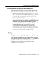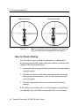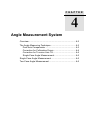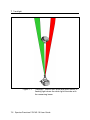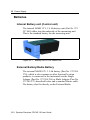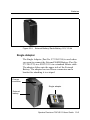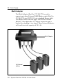
1
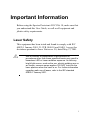
Spectra Precision
FOCUS 10
®
®
User Guide
Version 02.00
Part Number 571 257 201
August 2007
Contact details
Spectra Precision
10355 Westmoor Drive
Suite #100
Westminister, CO 80021
U.S.A.
+1-720-587-4700 Phone
888-477-7516 (Toll Free in U.S.A.)
www.spectraprecision.com
Copyrigt and Trademarks
Copyright © 2005-2007, Spectra Precision. All
rights reserved.
Autolock, FOCUS, Spectra Precision and Tracklight are
trademarks of Spectra Precision, registered in the
United States Patent and Trademark Office and other
countries. Spectra Precision logo is a Trademark of
Spectra Precision.
All other trademarks are the property of their
respective owners.
Release Notice
This is the August 2007 release version 02.00 of
the Spectra Precision FOCUS 10 User Guide,
part number 571 257 201. It applies to the
Spectra Precision FOCUS 10 total station.
The following limited warranties give you
specific legal rights. You may have others, which
vary from state/jurisdiction to state/jurisdiction.
Registration
To receive information regarding updates and
new products, please contact your local dealer or
visit the Spectra Precision website at
www.spectraprecision.com/register.
Upon registration you may select the newsletter,
upgrade or new product information you desire.
Notices
Australia and New Zealand
This product conforms
with the regulatory
requirements of the
Australian Communications Authority (ACA)
EMC framework, thus satisfying the
requirements for C-Tick Marking and sale within
Australia and New Zealand.
Canada
This Class B digital apparatus complies with
Canadian ICES-003
This digital apparatus does not exceed the Class
B limits for radio noise emissions from digital
apparatus as set out in the radio interference
regulations of the Canadian Department of
Communications.
Le présent appareil numérique n’émet pas de
bruits radioélectriques dépassant les limites
applicables aux appareils numériques de Classe
B prescrites dans le règlement sur le brouillage
radioélectrique édicté par le Ministère des
Communications du Canada.
N 10233
This device has been designed to operate with an
antenna having a maximum gain of 2.0 dBi.
Antenna having a higher gain is strictly
prohibited per regulations of Industry Canada.
The required antenna impedance is 50 ohms. To
reduce potential radio interference to other users,
the antenna type and its gain should be so chosen
that the equivalent isotropically radiated power
(EIRP) is not more than that required for
successful communication. Operation is subject
to the following two conditions: (1) this device
may not cause interference, and (2) this device
must accept any interference, including
interference that may cause undesired operation
of the device.
Europe
This product has been
tested and found to
comply with the
requirements for a Class B device pursuant to
European Council Directive 89/336/EEC on
EMC, thereby satisfying the requirements for CE
Marking and sale within the European Economic
Area (EEA). These requirements are designed to
provide reasonable protection against harmful
interference when the equipment is operated in a
residential or commercial environment.The alert
sign indicates the device is classified as a Class 2
device, implying that certain restrictions apply to
its use, according to the following:
Devices marked with Part Numbers 58050008,
58060008, 58070008 and 58080008 may be used
all over the European Community, excluding
France.
Devices marked with Part Numbers 58052008,
58062008, 58072008 and 58082008 is
exclusively for use in France.
The compliance to the applicable requirements is
detailed in the official Declaration of Conformity
document, which is filed at Spectra Precision.
For product recycling instructions and more
information, please go to
www.spectraprecision.com/ev.shtml.
Recycling in Europe: To recycle Spectra
Precision WEEE (Waste Electrical and
Electronic Equipment, products that run
on electrical power.), Call +31 497 53 24
30, and ask for the "WEEE Associate".
Or, mail a request for recycling instructions to:
Spectra Precision Europe BV
c/o Menlo Worldwide Logistics
Meerheide 45
5521 DZ Eersel, NL
USA
Class B Statement – Notice to Users. This
equipment has been tested and found to comply
with the limits for a Class B digital device,
pursuant to Part 15 of the FCC rules. These
limits are designed to provide reasonable
protection against harmful interference in a
residential installation. This equipment
generates, uses, and can radiate radio frequency
energy and, if not installed and used in
accordance with the instructions, may cause
harmful interference to radio communication.
However, there is no guarantee that interference
will not occur in a particular installation. If this
equipment does cause harmful interference to
radio or television reception, which can be
determined by turning the equipment off and on,
the user is encouraged to try to correct the
interference by one or more of the following
measures:
– Reorient or relocate the receiving antenna.
– Increase the separation between the equipment
and the receiver.
– Connect the equipment into an outlet on a
circuit different from that to which the
receiver is connected.
– Consult the dealer or an experienced radio/TV
technician for help.
Changes and modifications not expressly
approved by the manufacturer or registrant of
this equipment can void your authority to operate
this equipment under Federal Communications
Commission rules
The antenna used for this transmitter must be
installed to provide a separation distance of at
least 20 cm from all persons and must not be colocated or operating in conjunction with any
other antenna or transmitter:
FCC ID: HSW- 2410M.
Taiwan
Battery Recycling Requirements
The product contains a removable
Lithium-ion battery. Taiwanese
regulations require that waste batteries
are recycled.
Important Information
Before using the Spectra Precision® FOCUS® 10, make sure that
you understand this User Guide, as well as all equipment and
jobsite safety requirements.
Laser Safety
This equipment has been tested and found to comply with IEC
60825-1 January 2001, 21 CFR 1040.10 and 1040.11 except for
deviations persuant to Laser Notice no. 50, dated May 27, 2001.
C
Use of controls or adjustments or performance of
procedures other than those specified herein may result in
hazardous LED or Laser radiation exposure. As with any
bright light source, such as the sun, electric welding arcs or
arc lamps, common sense applies. DO NOT look into the
laser aperture when the laser is on. For further information
regarding safe use of lasers, refer to the IEC standard
60825-1 January 2001.
I
Queries
Address any questions you may have about laser safety to:
Spectra Precision
5475 Kellenburger Road
Dayton, OH U.S.A. 45424-1099
Attention: Laser Safety Officer, Quality Assurance Group
Phone +1-937-233-8921 ext 824 or 800 538-7800(Toll free in the
USA)
Fax +1-937-233-9661
Spectra Precision FOCUS 10
The FOCUS 10 contains one light source:
A laser diode for the distance measuring function operating at 850
nm (infrared, non-visible light), with a beam divergence of 0.4 x
0.8 mrad and an output power of < 0.48 mW, laser CLASS 1.
II
Environmental Information
NOTICE FOR SPECTRA PRECISION’S EUROPEAN UNION
CUSTOMERS
Spectra Precision is pleased to announce a
new recycling program for our European
Union customers. At Spectra Precision, we
recognize the importance of minimizing the
environmental impacts of our products. We
endeavor to meet your needs, not only when
you purchase and use our products, but also
when you are ready to dispose of them. That
is why Spectra Precision is actively pursuing,
and will continue to pursue, the expanded use
of environmentally friendly materials in all its
products, and why we have established a
convenient and environmentally friendly recycling program.
As Spectra Precision makes additional recycling facilities available for
your use, we will post their locations and contact information to our
Recycling Instructions web page.
For product recycling instructions and more information, please go to
www.spectraprecision.com/environment/summary.html
Recycling in Europe:
To recycle Spectra Precision WEEE,
Call +31 497 53 2430, and ask for the “WEEE Associate”
Or
Mail a request for recycling instructions to:
Spectra Precision
c/o Menlo Worldwide Logistics
Meerheide 45
5521 DZ Eersel, NL
I II
Declaration of Conformity
EC-Declaration of Conformity
to the Essential Requirements of the applicable
Directives, 89/336/EC and 73/23/EEC
including amendments by the CE marking Directive, 93/68/EEC
Product:
Instrument – Spectra Precision Focus 10
Types/Models
Focus 10 X
Focus CU
Manufacturer:
Part Numbers
571257003, 572257003
571257810, 572257810
Notes
X = Code for accuracy
Trimble AB
Box 64, Rinkebyvägen 17
SE-182 11 Danderyd
Sweden
This declaration is based on the full compliance of the products with the following European
harmonized standards:
EMC:
EN 61000-6-2:2001
EN 61000-4-2 (1995) + A1 (1998) + A2 (2001)
EN 61000-4-3:2002/A1/A2
EN 61000-6-3:2001
EN 55022/A1/A2 Class B
Laser Safety:
EN 60825-1:1994 + A1 (2002) + A2 (2001)
As manufacturer, we declare under our sole responsibility that the equipment follows the provisions of
the Directives stated above.
Danderyd 2007-06-21
Original signed
.........................................................
Martin Holmgren
Engineering Manager
Trimble AB
IV
Box 64, Rinkebyvägen 17
Telephone No: +46 8 622 1000
Telefax: +46 8 753 2464
SE-182 11 Danderyd, Sweden
www.trimble.com
Org.No: 556550-9782
VAT.No: SE556550978201
Table of Contents
1
Welcome
Welcome to Spectra Precision FOCUS 10 .................... 1-2
Glossary of terms used with the System (Only with FOCUS
10 CU) .................................................................. 1-2
2
Introduction
Unpacking & Inspection ................................................. 2-3
Inspection...................................................................... 2-3
Controls ......................................................................... 2-4
Pre-Measurement .......................................................... 2-6
Connecting the external battery to the instrument ........ 2-6
The Side Cover.............................................................. 2-7
The Central Unit............................................................. 2-8
Laser and LED Information............................................ 2-9
Spectra Precision FOCUS 10........................................ 2-9
3
Surveying methods
Overview........................................................................ 3-2
Conventional surveying with servo ................................ 3-2
Conventional surveying with Autolock ........................... 3-3
Aiming .......................................................................... 3-3
How to Check Aiming .................................................. 3-4
Robotic Surveying.......................................................... 3-5
Equipment ..................................................................... 3-5
4
Angle Measurement System
Overview........................................................................ 4-3
The Angle Measuring Technique ................................... 4-3
Table of Contents
Dual Axis Compensator................................................ 4-3
Correction for Collimation Errors................................. 4-4
Correction for Trunnion Axis Tilt................................. 4-4
Single-Face Angle Measurement.................................. 4-5
Two-Face Angle Measurement...................................... 4-5
5
Distance Measurement System
Overview........................................................................ 5-3
Distance Measurement.................................................. 5-3
Automatic control of signal level.................................. 5-4
Measurement range and accuracy ................................. 5-4
6
Servo
Overview........................................................................ 6-2
Servo controls................................................................ 6-2
Motion knobs ................................................................ 6-2
7
Tracklight
Overview........................................................................ 7-3
8
Tracker
Overview........................................................................ 8-2
9
Radio
Overview........................................................................ 9-2
Radio controls................................................................ 9-2
Select radio channel ...................................................... 9-2
Station address .............................................................. 9-2
Radio license................................................................. 9-3
Range ............................................................................ 9-3
Table of Contents
10
Power Supply
Batteries....................................................................... 10-2
Internal Battery unit (Central unit) ............................. 10-2
External Battery/Radio Battery................................... 10-2
Single Adapter ............................................................ 10-3
Multi Adapter.............................................................. 10-4
Battery Cables............................................................. 10-5
Battery Charging.......................................................... 10-6
Single Charger (572 906 330)..................................... 10-6
Super Charger (572 906 145) (Optional) .................... 10-7
Power Unit (572 906 146)........................................... 10-8
About charging NiMH (and NiCd) batteries............... 10-8
Bat Low....................................................................... 10-9
11
RMT Remote Targets
Overview...................................................................... 11-2
RMT 602 ...................................................................... 11-3
RMT 606 ...................................................................... 11-4
12
Care & Maintenance
Overview...................................................................... 12-2
Cleaning ...................................................................... 12-3
Condensation............................................................... 12-3
Packing for Transport.................................................. 12-3
Table of Contents
CHAPTER
1
1
Welcome
Welcome to Spectra Precision FOCUS 10........................... 1-2
Glossary of terms used with the System (Only with FOCUS 10
CU)....................................................................................... 1-2
1 Welcome
Welcome to Spectra Precision FOCUS 10
Wellcome to the Spectra Precision FOCUS 10 User Guide.
This manual describes the different functions of the
FOCUS 10 total station and how to best use it in order to
get most out of your equipment.
Even if you have used other surveying equipment before, it
is reccomended that spend some time reading this guide to
learn about the special features of this product.
Glossary of terms used with the System (Only
with FOCUS 10 CU)
Area File:
A file in the memory device that holds
known coordinates (Pno, N, E etc.) or
Roadline data.
A/M-key:
Aim/Measure button. Initiates a
measurement and controls search and
remote measurements.
D:
Accurate measurement with mean value
calc.
dH & dV:
These values represents the collimation
errors. When performing D-bar
measurements in two faces these errors do
not affect the accuracy of the measurement
(HA, VA). If the values differs a lot from 0
it is recommended that you perform a test
measurement (MNU5).
Free Station: Also known as Resection. Location of the
total station by measuring distance and/or
angles to 2 or up to 8 points.
1-2 Spectra Precision FOCUS 10 User Guide
Glossary of terms used with the System (Only with FOCUS 10 CU)
FSTD:
Fast Standard measurement, with A/M.
IH:
Instrument height over the point.
Job File:
A file in a the memory device that holds
data collected in the field. This file can
consist of any data.
Logon:
Entering Job file and memory unit when
designing a U.D.S with program 40.
Offset:
Length offset to measured slope distance.
Prism const:
The prism’s length offset from the
0-constant.
Ref. Obj:
Reference Object, also back sight.
REG-key:
The register key. This stores data in the
data collector.
R.O.E:
Remote Object Elevation.
SH:
Signal height.
STD:
Standard measurement, with A/M.
TRK:
Tracking measurement, automatic and
continuous measurement.
U.D.S.:
User Defined Sequence. A program
designed by the user determining what is
Spectra Precision FOCUS 10 User Guide 1-3
1 Welcome
collected, its order of collection and how it
is displayed on the screen.vm
SH
dELE
IH
ELE
1-4 Spectra Precision FOCUS 10 User Guide
Point to set out
CHAPTER
2
2
Introduction
Unpacking & Inspection ....................................................... 2-3
Inspection........................................................................ 2-3
Controls................................................................................ 2-4
Pre-Measurement ................................................................ 2-6
Connecting the external battery to the instrument .......... 2-6
The Side Cover .................................................................... 2-7
The Central Unit ................................................................... 2-8
Laser and LED Information .................................................. 2-9
Spectra Precision FOCUS 10 ......................................... 2-9
2 Introduction
Figure 2.1
FOCUS 10 Series
2-2 Spectra Precision FOCUS 10 User Guide
Unpacking & Inspection
Unpacking & Inspection
Before we begin to describe the operating procedure of
your Spectra Precision FOCUS 10, it is first necessary to
acquaint yourself with the equipment received:
•
•
•
•
•
•
•
Instrument Unit
Transport case
Tribrach
Rain cover
Reflective sight marks (stick-on)
User Manual (CD only)
Tool kit
Note – Some equipment is market dependent
Inspection
Inspect the shipping container. If it is received in poor
condition, examine the equipment for visible damage. If
damage is found, immediately notify the carrier and your
sales representative. Keep the container and packing
material for the carrier’s inspection.
Spectra Precision FOCUS 10 User Guide 2-3
2 Introduction
Controls
Here you find a list of the controls of your instrument.
Please take at moment to familiarize yourself with the
names and the locations of the controls.
Coarse sight
Central unit Internal battery or
Tracklight and/or
Tracker
Vertical motion
servo control
Horizontal motion
servo control
Figure 2.2
FOCUS 10 instrument shown from the operator
side (back).
2-4 Spectra Precision FOCUS 10 User Guide
Controls
Prism symbol
(which marks the instrument
height (IH), also on the
opposite side cover)
Figure 2.3
FOCUS 10 instrument seen from the side.
Spectra Precision FOCUS 10 User Guide 2-5
2 Introduction
Pre-Measurement
Connecting the external battery to the instrument
The instrument can be equipped with an external battery
that is connected to the instrument via the battery cable.
The cable is to be connected to the connector on the
instrument resp. battery as shown in the picture below.
Figure 2.4
Connecting the external battery to the instrument.
2-6 Spectra Precision FOCUS 10 User Guide
The Side Cover
The Side Cover
The instrument can be configured with two different side
covers; a plain or a radio unit cover. It is possible to change
side cover if you need another type, but it has to be done at
a Spectra Precision authorized service center.
Plain Cover
Radio Unit Cover
The radio unit cover is needed when you
wish to use the instrument for remote
surveying or robotic surveying (one-person
total station), Equipment
Spectra Precision FOCUS 10 User Guide 2-7
2 Introduction
The Central Unit
The central unit can be configured with the internal battery,
the Tracklight® or the tracker unit. You can change between
battery unit and Tracklight by yourself, but the tracker unit
must be installed at a Spectra Precision authorized service
center.
Internal battery
The internal battery gives you
2 hours of continuous use.
Tracklight
Tracklight is a visible guide
light which is an aid to the
rodman e.g. when setting out.
Tracker
The tracker has control of the
instruments when using the
system for robotic surveying
(one-person system) or in
Autolock® mode.
2-8 Spectra Precision FOCUS 10 User Guide
Laser and LED Information
Laser and LED Information
Spectra Precision FOCUS 10
The FOCUS 10 has been tested and complies with the
regulations for a Class 1 Laser product. See laser safety
information on the first pages of this manual.
Distance
Measuring Laser
aperture
Figure 2.5
Laser aperture
Spectra Precision FOCUS 10 User Guide 2-9
2 Introduction
2-10 Spectra Precision FOCUS 10 User Guide
CHAPTER
3
3
Surveying methods
Overview .............................................................................. 3-2
Conventional surveying with servo....................................... 3-2
Conventional surveying with Autolock.................................. 3-3
Aiming ............................................................................. 3-3
How to Check Aiming...................................................... 3-4
Robotic Surveying ................................................................ 3-5
Equipment....................................................................... 3-5
3 Surveying methods
Overview
This chapter will describe the different ways of working
with the FOCUS 10. Since the instrument is equipped with
servo drive, you’ll find that the system is very easy to
handle, when setting out you can with a touch of a single
key aim the instrument towards the set out point.
Conventional surveying with servo
Your instrument is equipped with servo drive, this means a
lot of advantages:
• In e.g. setting out you only need to give the point
number. The instrument will calculate and aim
automatically towards the precalculated bearing with a
single press of the positioning key
.
• For angle measurements, just aim towards the different
reflector stations once. The instrument remembers and
repeats the aiming process how ever many times and in
what ever order you want. Fine adjustments might be
needed.
• During aiming, the servo assists the horizontal and
vertical adjustments. All that’s needed is a light circular
movement of the adjustment screw with your finger tip.
• Thanks to servo-drive, adjustments screws have no end
positions. That means no unnecessary interruptions,
when aiming.
3-2 Spectra Precision FOCUS 10 User Guide
Conventional surveying with Autolock
Conventional surveying with Autolock
With the feature Autolock, you do no longer have to fine
adjust or focus, since this is taken care of by the system.
• To upgrade a base unit to Autolock, you’ll only need to
add a Tracker unit and an RMT target. It is also possible
to measure in a conventional way without Autolock
using an ordinary reflector.
• When setting out, you’ll only need to supply a prestored
point and the system will calculate the necessary data for
setting out. Then, position the instrument with the
positioning key. When the rodman, guided by the builtin Tracklight enters the Tracker’s field of view
(2.5m/100m), the instrument locks onto the RMT
automatically. You’re now able to fully concentrate on
the information in the display (radial/right angle offset)
and direct the rodman to the setting out point.
Aiming
The adjustment between the two optical axes, the telescope
and the tracker, may differ. The difference will make it
seem like the instrument does not point towards the center
of the prism, when using Autolock, figure 3.1. This is not a
problem since the two axis have their own separate
collimation data. It is however important to make
collimation test for both axes.
Spectra Precision FOCUS 10 User Guide 3-3
3 Surveying methods
Manual aiming
Figure 3.1
Autolock aiming
Difference between aiming manually and Autolock
(The error has been exaggerated in the figure)
How to Check Aiming
You can check how well the instrument is calibrated by
measuring toward the prism with and without Autolock and
compare the measured angles:
1. Aim manually at a prism and read out the horizontal and
vertical angles.
2. Turn on Autolock and let the instrument lock on to the
same prism automatically, read out the horizontal and
vertical angles.
3. Compare the angles between manual and Autolock
aiming.
If the difference between the read out angles is significant,
you should carry out both a horizontal and vertical angle
3-4 Spectra Precision FOCUS 10 User Guide
Robotic Surveying
collimation adjustment, and a tracker collimation
adjustment.
Robotic Surveying
By equipping the instrument with a tracker unit, even
aiming can be done from the measuring point. The entire
measurement is performed from the point, with the same
access to all functions of the total station as if you were
standing beside it.
Robotic surveying means higher production capacity.
During setting-out, it’s best with two people: one to handle
the measuring with the robotic rod, and one to mark the
points. Of course, the entire job can be performed by a
single person. The unique search function makes robotic
surveying extremely efficient 24 hours a day.
Equipment
To be able to work with robotic surveying you’ll need a
data collector, instrument with a radio side cover and
tracker unit, an RMT (Remote Target) and an external radio
connected to the collector. The data collector, external radio
and RMT will hereafter be called, Robotic rod.
Spectra Precision FOCUS 10 User Guide 3-5
3 Surveying methods
3-6 Spectra Precision FOCUS 10 User Guide
CHAPTER
4
4
Angle Measurement System
Overview .............................................................................. 4-3
The Angle Measuring Technique.......................................... 4-3
Dual Axis Compensator .................................................. 4-3
Correction for Collimation Errors..................................... 4-4
Correction for Trunnion Axis Tilt...................................... 4-4
Single-Face Angle Measurement.................................... 4-5
Single-Face Angle Measurement......................................... 4-5
Two-Face Angle Measurement ............................................ 4-5
4 Angle Measurement System
Automatic correction
for deviation in relation
to the plumb axis
Automatic correction
for collimation error
Automatic correction
for trunnion axis tilt
Figure 4.1
The Angle Measurement System
4-2 Spectra Precision FOCUS 10 User Guide
Overview
Overview
The FOCUS 10 meets all demands for efficient and
accurate angle measurement. It also allows you to choose
the measuring method with which you feel most
comfortable. The angle measurement system gives you full
compensation for the following:
• Automatic correction for angle sensor errors.
• Automatic correction for collimation error and trunnion
Axis tilt.
• Automatic correction for tracker collimation error.
• Arithmetic averaging for elimination of pointing errors.
The Angle Measuring Technique
One of the strong features of the design of the FOCUS 10 is
its electronic angle measurement system, which eliminates
the angle errors that normally occur in conventional
theodolites. The principle of measurement is based on
reading an integrated signal over the whole surface of the
angle sensor and producing a mean angular value. In this
way, inaccuracies due to eccentricity and graduation are
eliminated.
Dual Axis Compensator
The instrument is also equipped with a dual axis
compensator which will automatically correct both
horizontal and vertical angles for any deviations in the
plumb line. The system warnes immediately of any
deviations in excess of ±10c (6’).
Spectra Precision FOCUS 10 User Guide 4-3
4 Angle Measurement System
Correction for Collimation Errors
By carrying out a simple pre-measurement test procedure
both horizontal and vertical collimation of the instrument
can be quickly measured and stored. All angles measured
thereafter are automatically corrected. These collimation
correction factors remain in the internal memory until they
are measured again.
Correction for Trunnion Axis Tilt
During the same pre-measurement test procedure, it is also
possible to measure and store angular imperfections of the
horizontal tilt axis relative to the horizontal axis. This
stored correction factor is applied automatically to all
measured horizontal angles.
When should these tests be carried out?
1. After transport where hard handling may have occurred.
2. When the temperature differs by > 10 ºC from the
previous application.
3. Immediately prior to high precision angle measurement.
How are these tests carried out?
See “Test Measurements”, chapter 4 in FOCUS 10 CU User
Guide General Part 1.
4-4 Spectra Precision FOCUS 10 User Guide
Two-Face Angle Measurement
Single-Face Angle Measurement
The above described features admits efficient and accurate
angle measurement in a single face, since the instruments
errors are automatically corrected with constants which
were stored during the test measurement.
During Single Face angular measurements, with the
compensator engaged and pre-measurement and storage of
collimation and tilt axis errors have been executed, each
displayed angle will be compensated for the following:
• Horizontal and vertical circle graduation and
eccentricity errors.
• Plumb line deviation errors.
• Horizontal and vertical collimation errors.
• Tilt axis errors.
It is worth mentioning that human error sources such as
telescope sighting (these errors can be almost nullified by
measuring in two faces) and imperfections in the optical
plummet of the tribrach still remain.
Two-Face Angle Measurement
The instrument can be used in exactly the same manner as a
conventional theodolite, i.e. in both the left and right face.
These two-face situations will hereafter be referred to as
Circle 1 and Circle 2 positions. Two face measurements can
be used for legal reasons, or when additional concern of
accuracy and documentation is demanded.
When measuring in STD-mode you measure and store each
angle value of the two faces and get a display value of the
total collimation and sighting error.
Spectra Precision FOCUS 10 User Guide 4-5
4 Angle Measurement System
When measuring in D-bar mode you can decrease the
sighting error by repeating measurements and mean value
calculation of each sighting. The number of repeated
sightings can be chosen depending on the current
measuring conditions. The final mean value calculated
angles are displayed and stored in this mode. Angle values
for each face are also available.
4-6 Spectra Precision FOCUS 10 User Guide
CHAPTER
5
5
Distance Measurement System
Overview .............................................................................. 5-3
Distance Measurement ........................................................ 5-3
Automatic control of signal level ..................................... 5-4
Measurement range and accuracy ................................. 5-4
5 Distance Measurement System
5-2 Spectra Precision FOCUS 10 User Guide
Overview
Overview
The distance module of FOCUS 10 operates within the
infrared area of the electromagnetic spectrum. It transmits
an infrared light beam. The reflected light beam is received
by the instrument and, with the help of a comparator, the
phase delay between transmitted an received signal is
measured. The time measurement of the phase delay is
converted and displayed as a distance with mm accuracy.
Note – When taking measurements with servo instruments
and having the Tracker installed there may be a distance
error if you use large prisms.
Distance Measurement
The internal function of the distance measurement module
can be varied depending on the nature of the particular
survey application in question. There are four methods of
distance measurement
STD
Standard measurements towards stationary
targets (standard mode)
STD
Fast measurements towards stationary
targets (fast standard mode)
D
TRK
Precision measurements towards stationary
targets (arithmetical mean value D-bar
mode)
Measurements towards moving targets
(tracking mode) e.g setting out or
hydrographic surveying. Also functions as
automatic measuring mode for polar
measurement and tacheometry.
Spectra Precision FOCUS 10 User Guide 5-3
5 Distance Measurement System
The choice of measurement method is often based on the
experience of the operator and of course the practical
precision demanded by the current survey task.
Automatic control of signal level
The FOCUS 10 total station has an automatic signal control
which adjusts the measurement signal level to an optimal
value of each distance measured.
Measurement range and accuracy
Since the Spectra Precision instruments are constantly
improved we refer to the Technical Specifications sheets for
the up-to-date measurement range and accuracy figures of
the respective models.
5-4 Spectra Precision FOCUS 10 User Guide
CHAPTER
6
6
Servo
Overview .............................................................................. 6-2
Servo controls ...................................................................... 6-2
Motion knobs................................................................... 6-2
6 Servo
Overview
The FOCUS 10 is equipped with servo controlled motors
for positioning of the unit. The servo is in use when
performing a number of different operations; when turning
the motion knobs, when positioning with the servo control
keys, for automatic test and calibration or when using the
tracker for robotic surveying..
Servo controls
Motion knobs
The servo is manually controlled by the two motion knobs
located at the side of the instrument.
The motion knobs are sensitive in four steps so that the
more you turn the knob the faster the servo will rotate the
instrument.
If you want to switch to fine mode adjustment when
operating a motion knob, turn the opposite direction and
fine adjust.
Vertical motion knob
Horizontal motion knob
6-2 Spectra Precision FOCUS 10 User Guide
CHAPTER
7
7
Tracklight
Overview .............................................................................. 7-3
7 Tracklight
Figure 7.1
Tracklight® emits a red, white and green sector of
flashing light where the white light coincides with
the measuring beam.
7-2 Spectra Precision FOCUS 10 User Guide
Overview
Overview
Tracklight is a visible guide light which enables the rodman
to set himself on the correct bearing. It consists of a
flashing three coloured light, each colour lying within its
own lateral projection sector. If the rodman is to the left of
the measuring beam, he will observe a green flashing light;
if to the right, a red flashing light; if on-line with the
measuring beam of the instrument, a white flashing light.
The frequency of the flash will increase by 100% as soon as
the light beam strikes the reflector, which will confirm for
the staff – man that he/she is holding the rod in the correct
position. Once the rodman is on-line, the distance will
immediately appear on the display. Tracklight also provides
the operator with an excellent facility for clearing sight
lines and for working during the hours of darkness.
The instrument measuring beam width at 100 m is 15 cm.
The width of the Tracklight beam at the same distance is
10 m.
The Tracklight unit slides onto the underside of the
measuring unit or if the instrument is equipped with a
tracker the Tracklight is a part of the tracker unit. The
Tracklight is activated from the data collector.
Spectra Precision FOCUS 10 User Guide 7-3
7 Tracklight
7-4 Spectra Precision FOCUS 10 User Guide
CHAPTER
8
8
Tracker
Overview .............................................................................. 8-2
8 Tracker
Overview
FOCUS 10 can be equipped with a Tracker unit which is
needed when using the system for robotic surveying or
when performing conventional surveying with Autolock.
The tracker has control over the instrument’s servos and
aims the instrument correctly towards the target, which in
these cases must be an RMT (Remote Target). An
automatic search function is optional.
8-2 Spectra Precision FOCUS 10 User Guide
CHAPTER
9
9
Radio
Overview .............................................................................. 9-2
Radio controls ................................................................. 9-2
Select radio channel ....................................................... 9-2
Station address ............................................................... 9-2
Radio license .................................................................. 9-3
Range ............................................................................. 9-3
9 Radio
Overview
To be able to communicate between the instrument and the
robotic rod the instrument must be equipped with a radio
side cover and the data collector must be connected to an
external radio. The radio side cover consists of a built in
radio and an antenna.
Radio controls
Select radio channel
The radio channel is selected from the Control Unit. Up to
12 channels can be used depending on how many are
supplied or permitted by authorities in each country. Select
a channel when the CU is attached to the instrument. Then
when the CU is detached and connected to the external
radio, this radio will automatically get the same channel as
the instrument. The range of different channels makes it
possible to work with more then one FOCUS 10 at a
working site. It is though important that each system has its
own radio channel so that not any disturbances will occur.
Station address
If disturbances occur on the radio channel from other
systems in the same area, try to change channel. If that does
not help the instrument and the robotic rod can be given an
unique address. Choose menu 1.5, Radio with the data
collector attached to the instrument. Here you are prompted
to enter a station address and a remote address between 0
and 99.
9-2 Spectra Precision FOCUS 10 User Guide
Radio controls
Radio license
Note that the radio frequencies used are not harmonized
within EC and only permitted in one particular country or
area. Make sure that your radio is intended for the country,
where it is to be used. The information of destination
country can be found on the External radio or on its
package.
Before using the system at your working site it is important
to know that in some countries it is necessary to have a user
license. Make sure that your local agent has informed you
about the regulations in your country.
Range
The actual range in which the radio can work is depending
on the conditions. Range can be decreased if other radios
are in operation in your area or when you are working in an
area with many reflecting objects.
Spectra Precision FOCUS 10 User Guide 9-3
9 Radio
9-4 Spectra Precision FOCUS 10 User Guide
CHAPTER
10
Power Supply
10
Batteries ............................................................................. 10-2
Internal Battery unit (Central unit) ................................. 10-2
External Battery/Radio Battery...................................... 10-2
Single Adapter .............................................................. 10-3
Multi Adapter................................................................. 10-4
Battery Cables .............................................................. 10-5
Battery Charging ................................................................ 10-6
Power Unit (572 906 146) ............................................. 10-8
About charging NiMH (and NiCd) batteries................... 10-8
Bat Low ......................................................................... 10-9
10 Power Supply
Batteries
Internal Battery unit (Central unit)
The internal NiMH 12 V, 1.8 Ah battery unit (Part Nr. 572
257 460) slides into the underside of the measuring unit.
This is the standard battery for the measuring unit.
Figure 10.1
Battery unit 12V for central unit.
External Battery/Radio Battery
The external NiMH 12V, 3.5 Ah battery (Part No. 572 204
270), which is also common to other Spectra Precision
products, is connected to the instrument via the Single
Adapter (Part No. 572 204 256) or Multi Adapter (Part No.
572 204 273) described below and a standard Hirose cable.
The battery also fits directly on the External Radio.
10-2 Spectra Precision FOCUS 10 User Guide
Batteries
Figure 10.2
External Battery/ Radio Battery, 12V, 3.5 Ah
Single Adapter
The Single Adapter (Part No. 572 204 256) is used when
you want to connect the External NiMH Battery (Part No.
572 204 270) to a FOCUS 10 via a standard Hirose cable.
The adapter slides onto the upper side of the External
Battery. The adapter has two Hirose connectors and a
bracket for attaching it to a tripod.
Charger
connector
Single adapter
External
battery
Spectra Precision FOCUS 10 User Guide 10-3
10 Power Supply
Multi Adapter
The Multi Adapter (Part No. 572 204 273) is used to
connect up to three External NiMH Battery units (Part No.
572 204 270) to a FOCUS 10 via a standard Hirose cable.
The adapter slides onto the upper sides of the External
Batteries. The adapter has 2+2 Hirose connectors and a
bracket for attaching it to a tripod. Three External Batteries
will result in a total capacity of 10.5 Ah
.
Multi Adapter
3x External
battery
10-4 Spectra Precision FOCUS 10 User Guide
Batteries
Battery Cables
The multi functional cable is required if an external battery
is used or when connecting the different Spectra Precision
devices with each other. The different types of cables are
listed below:
Multi functional Cable 1m, 572 202 188, for connecting
the FOCUS 10 or control unit to an external battery via the
Single or Multi Adapter or to another control unit or
instrument. Length: 1.0m.
Multi functional Cable 2.5m, 572 202 216, same as the
above cable. Length: 2.5m.
Multi functional Cable 0,4m, 572 208 043, same as the
above cable. Length: 0.4m.
Multi functional spiral cable 0.75-1.75m, 572 208 068,
same as the above cable. Length: 0.75-1.75m.
Data Communication Adapter, 572 202 204, for
connecting the FOCUS 10 or control unit to a computer and
Power Supply or an external battery using the Single or
Multi Adapter.
Spectra Precision FOCUS 10 User Guide 10-5
10 Power Supply
Battery Charging
When charging the batteries to a FOCUS 10, it is important
to use a charger dedicated to charging NiMh and NiCd
batteries. The different types of chargers available are
described in the following.
Single Charger (572 906 330)
A 230 or 115 VAC single battery charger. The charger has a
single Hirose output that can handle one NiMH External
Battery (572 204 270). Use together with Power Cable 571
905 925 (100-115V), 571 905 924(220V) or 571 908 040
(230V, UK plug) and Charger Cable 572 208 020 (for other
batteries).
10-6 Spectra Precision FOCUS 10 User Guide
Battery Charging
Super Charger (572 906 145) (Optional)
A microprocessor controlled charger for sequential
charging of up to four Spectra Precision NiMH or NiCd
batteries. It is run with 10-30 VDC and is fitted with a
connector to suit both 19mm and 12mm cigarette lighter
sockets. It shall only be used together with Power Unit (572
906 146). The ambient temperature while charging should
be between +-0 ºC and +40 ºC. Use together with Charger
Cable 572 208 020 (for other batteries).
Warning – The Super Charger is for use together with Power
Unit 572 906 146 only! Other power units or charging
converters must never be used together with Super Charger.
Spectra Precision FOCUS 10 User Guide 10-7
10 Power Supply
Power Unit (572 906 146)
A 90-260 VAC charging converter for use together with
Super Charger (572 906 145). The Power Unit is equipped
with a cigarette lighter socket and two Hirose connectors
for FOCUS 10 system cabling. Use together with Power
Cable 571 905 924 (230V), 571 905 925 (100-115V) or 571
908 040 (230V, UK plug).
About charging NiMH (and NiCd) batteries
The temperature while charging should be above +5 ºC but
should not exceed room temperature. The condition of the
battery will be better preserved if it is used until the FOCUS
10 indicates “Bat Low” and the automatic cut-out function
is activated. Discharge of stored batteries can vary
considerably, depending on the quality of the individual
cells, especially at higher temperatures. It is therefore
10-8 Spectra Precision FOCUS 10 User Guide
Battery Charging
recommended to store them in room temperature or lower
and recharge batteries if they have been stored for a longer
period than two one month.
Note – Please refer to the battery chargers instructions.
Bat Low
When battery capacity drops too low, “Bat Low” appears in
the display window, and the instrument shuts off
automatically. This gives you an opportunity to change the
battery without losing instrument parameters and functions
such as instrument height, signal height, coordinates,
bearing, dual axis compensation, etc. Note that the battery
change must be made within 2 hours; otherwise the above
parameters and functions will be reset.
Note – This safety backup of the instrument’s parameters
and functions will work only when “Bat Low” appears on
the display: It will not function if the battery is removed
during operation.
Spectra Precision FOCUS 10 User Guide 10-9
10 Power Supply
10-10 Spectra Precision FOCUS 10 User Guide
CHAPTER
11
11
RMT Remote Targets
Overview ....................................................................... 11-2
RMT 602 ....................................................................... 11-3
RMT 606 ....................................................................... 11-4
11 RMT Remote Targets
Overview
FOCUS 10 instruments equipped with an optional Tracker
unit can perform surveying tasks using the Autolock
function. If the instrument is upgraded with a radio, you
will also be able to perform Robotic surveying, i.e oneperson surveying. To be able to use the above functions you
must also use some type of Remote Measuring Target
(RMT). A Spectra precision Remote Measuring Target
consists of a prism reflector and one or several active
tracker diodes. The great advantage of using active tracker
diode(s) is that you eliminate the risk of the instrument
locking on to other reflecting objects than the RMT. The
RMT complies with the regulations for a Class 1 LED
device.
Note – The typical range of the RMT is depending on the
weather conditions.
11-2 Spectra Precision FOCUS 10 User Guide
RMT 602
RMT 602
RMT602 (Part No. 572 202 220) is the standard remote
target for FOCUS 10. It can be used for distances up to 350
m and consists of a tracker diode unit with a miniature
prism (Part No. 571 126 060) mounted in front (not
included). The RMT602 remote target is powered by two
standard 1.5V size LR6/AA replaceable batteries which fits
into the unit. RMT602 can also be powered externally via
the Hirose contact.
Spectra Precision FOCUS 10 User Guide 11-3
11 RMT Remote Targets
RMT 606
RMT606 (Part No. 572 204 610) is an optional 360° remote
target for FOCUS 10. It can be used for distances up to 350
m. The RMT consists of a tracker diode unit with a set of
active diodes forming a full 360 degree circle and a 360°
prismring (Part No. 571 204 312)(not included). The
RMT606 remote target is powered externally via the Hirose
contact or directly from the power pole.
11-4 Spectra Precision FOCUS 10 User Guide
CHAPTER
12
Care & Maintenance
12
Overview ............................................................................ 12-2
Cleaning ............................................................................. 12-3
Condensation ..................................................................... 12-3
Packing for Transport......................................................... 12-3
Service ............................................................................... 12-3
12 Care & Maintenance
Overview
The Spectra Precision total station is designed and tested to
withstand field conditions, but like all other precision
instruments, it requires care and maintenance.
• Avoid rough jolts and careless treatment.
• Keep lenses and reflectors clean. Always use lens paper
or other material intended for cleaning optics.
• Keep the instrument protected in an upright position,
preferably in its transport case.
• Don´t carry the instrument while mounted on the tripod
in order to avoid damage to the tribach screws.
• Do not rotate the instrument by the handle. This may
have an affect on the HA ref. How much it effects the
value depends on the quality of the tribach and the
tripod. Use instead the servo controls to rotate the
instrument.
• Don´t carry the instrument by the telescope barrel. Use
the handle.
• When you need extremely good measurement precision,
make sure the instrument has adapted to the surrounding
temperature. Great variations of instrument temperature
could affect the precision.
Warning – The FOCUS 10 is designed to withstand normal
electromagnetic disturbance from the environment. However,
the instrument contains circuits sensitive to static electricity
and the instrument cover must not be removed by
unauthorized personnel. If the instrument cover has been
opened by an unauthorized person, the function of the
instrument is not guaranteed and the instrument warranty
becomes invalid.
12-2 Spectra Precision FOCUS 10 User Guide
Overview
Cleaning
Caution must be exercised when the instrument is cleaned,
especially when sand and dust are to be removed from
lenses and reflectors. Never use coarse or dirty cloth or hard
paper. Anti-static lens paper, cotton wad or lens brush are
recommended. Never use strong detergents such as benzine
or thinner on instrument or case.
Condensation
After survey in moist weather the instrument should be
taken indoors, the transport case opened and the instrument
removed. It should then be left to dry naturally. It is
recommended that condensation which forms on lenses
should be allowed to evaporate naturally.
Packing for Transport
The instrument should always be transported in its transport
case, which should be locked.
For shipment to a service shop, the names of the sender and
receiver should always be specified clearly on the transport
case.
When sending this instrument for repair, or for other service
work, a note describing fault, symptoms or requested
service should always be enclosed in the transport case.
Service
We recommend that you, once a year, leave the instrument
to an authorized service workshop for service. This is to
guarantee that the specified accuracies are maintained. Note
that there are no user servicable parts inside the instrument.
Spectra Precision FOCUS 10 User Guide 12-3
12 Care & Maintenance
12-4 Spectra Precision FOCUS 10 User Guide
SPECTRA PRECISION®
FOCUS™ 10 TOTAL STATION
GETTING STARTED GUIDE
Spectra Precision
7401 Church Ranch Blvd
Westminster, CO 80021
USA
+1-303-323-4100 Phone
888-477-7516 (Toll Free in USA)
www.spectraprecision.com