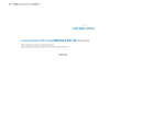
1
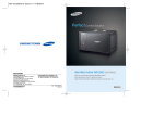
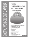
Ultimate
Sensitivity
Extreme Low Light Camera SHC-750 User’s Manual
SALES NETWORK
•
SAMSUNG TECHWIN CO., LTD.
145-3, Sangdaewon 1-dong, Jungwon-gu, Seongnam-si,
Gyeonggi-do 462-703, Korea
TEL : +82-31-740-8137~8139 FAX : +82-31-740-8145
•
SAMSUNG OPTO-ELECTRONICS UK, LTD.
Samsung House, 1000 Hillswood Drive, Hillswood Business
Park Chertsey, Surrey KT16 OPS
TEL : +44-1932-45-5308 FAX : +44-1932-45-5325
www.samsungtechwin.com
www.samsungcctv.com
•
TIANJIN SAMSUNG OPTO-ELECTRONICS CO., LTD.
7 Pingchang Rd, Nankai Dist. Tianjin 300190, P.R China
TEL : +86-22-2761-4724(33821) FAX : +86-22-2761-6514
Thank you for purchasing a SAMSUNG CCD CAMERA.
Before attempting to connect or operate this product,
please read these instructions carefully and save this manual for future use.
P/No. : Z6806-0762-01B
VAN 06. 09
ENGLISH
The lightning flash with an arrowhead symbol, within an equilateral triangle is
intended to alert the user to the presence of uninsulated “dangerous voltage”
within the product's enclosure that may be of sufficient magnitude to
constitute a risk of electric shock to persons.
The exclamation point within an equilateral triangle is intended to alert the user
to the presence of important operating and maintenance (servicing)
instructions in the literature accompanying the appliance.
INFORMATION -This equipment has been tested and found to comply with limits
for a Class A digital device, pursuant to part 15 of the FCC Rules. These limits are
designed to provide reasonable protection against harmful interference when the
equipment is operated in a commercial environment. This equipment generates,
uses, and can radiate radio frequency energy and, if not installed and used in
accordance with the instruction manual, may cause harmful interference to radio
communications.
Operation of this equipment in a residential area is likely to cause harmful
interference in which case the user will be required to correct the interference at
his own expense.
WARNING - Changes or modifications not expressly approved by the manufacturer
could void the user’s authority to operate the equipment.
CAUTION : To prevent electric shock and risk of fire hazards:
Do NOT use power sources other than that specified.
Do NOT expose this appliance to rain or moisture.
This installation should be made by a qualified service person and
should conform to all local codes.
Major Functions and Features
EMCCD for Extreme Light
Sensitivity
A 1/2 inch Electron Multiplying Charge
Coupled Device (EMCCD) and advanced
digital signal processing technology are
employed to produce sharper shapes and
colors in the subject image, even under
ultra low light conditions. This is suitable
for 24-hour outdoor surveillance where
available light levels can get extremely low.
-Color: 0.008Lux (F1.2, EIAJ)
-B/W: 0.0005Lux (F1.2, EIAJ)
SHC-750 DSP
The high performance DSP capability of the
SHC-750 effectively eliminates low light
noise and produces not only clearer images
but also sharper colors. The resulting
image is vivid and precise.
Motion Detection
The product’s Motion Detection feature detects
moving subjects and generates a signal
accordingly. An alarm device may be connected
directly (i.e. with no external sensor) to the
product for more effective security.
Video-Drive/DC-Drive Lens
Support
Video-drive lens or DC-drive lens selection
is by a simple switch control. The
brightness of the video lens can be
adjusted without fine VR adjustments.
Samsung Super Noise Reduction
(SSNR)
Samsung original SSNR technology effectively
eliminates low light noise, increases horizontal
resolution, and improves the S/N ratio.
The resulting image is clear and vivid even in
low light conditions.
On-Screen Text Display & RS-485
Communication Technology
Day & Night
It automatically distinguishes between day
and night, and switches to the appropriate
mode. Color mode is used during the day
to produce optimum color images; B/W
mode is used at night to deliver clearer
images in the dark.
Camera functions may be controlled using
the on-screen text displays.
RS-485 communication technology enables
long-distance remote control of the camera
functions.
Extra Features
Extra features include Sens-Up, Privacy,
Sharpness, Smear Cancel, and Mirror.
Samsung Techwin cares for the environment at all product manufacturing
stages to preserve the environment, and is taking a number of steps to
provide customers with more environment-friendly products.The Eco mark
represents Samsung Techwin s will to create environment-friendly products,
and indicates that the product satisfies the EU RoHS Directive.
Warnings & Cautions
This information is provided to ensure your safety and to prevent any losses, financial or
otherwise. Please read it carefully and use the product accordingly.
Warning/Attention/Special Mark Messages
Ignoring this information may result in material loss and/or serious
personal injuries including death.
Indicates “Never Allowed.”
Indicates “No Disassembling.”
Indicates Must Observe.
Contents
Precautions
8
Product Components
10
Names and Functions of Each Part
11
• Front
• Bottom
• Back
11
12
13
Instructions: Setup
14
• Lens
Using Auto Iris Lenses
Using C/CS Mount Lenses
14
Instructions: Camera Operation
20
• Menu Functions
• Function Settings
CAMERA ID
BACKLIGHT
WHITE BAL
MOTION DET
LENS SELECTION
SHUTTER
AUTO GAIN CONTROL
SENS-UP
SSNR
SPECIAL
20
21
22
24
26
27
28
29
30
30
32
33
Remote Control / MD Output / D&N Input
35
Problems & Solutions
36
Instructions: Connection
18
Product Specification
37
• Connecting a Monitor
• Connecting the Power
18
19
Protocol Command Description
38
Precautions
Installation of this product by unqualified
personnel is strictly prohibited.
If the camera overheats or smoke is
noticed, turn the power off immediately.
Experience and technical know-how are required
for proper installation, and to prevent possible fire
or electric shock. Please consult an authorized
retailer for any installation questions.
It may cause fire.
Do not install the product in an area of high humidity
or near flammable materials (e.g. oil or gas).
Do not install the product unless the location
can fully support the product’s weight.
Using the product in an incorrect environment may
cause fire, electric shock, or damage to the product.
If it is not properly supported, the product may fall.
Do not handle power plugs with
wet hands.
Do not insert foreign objects into the
product or disassemble the product.
It may cause electric shock.
COLOR CCD CAMERA
It may cause fire or damage the product.
8
User’s Manual
Do not expose the product to extreme
heat or cold.
Do not use the product in areas where the
illumination levels fluctuate frequently.
Do not expose the product to extreme heat or cold. Temperatures outside
its operating temperature range (-10˚C(14˚F) ~ 50˚C(122˚F)) may reduce
image quality or cause product malfunction. Pay special attention to
ventilation around the product in warm locations.
Fluctuating light levels caused by an unstable
fluorescent lamp, for example, may cause product
malfunction.
Do not drop, shake, or apply severe
impact to the product.
Do not point the camera towards a
strong light source such as the sun.
It may damage the product.
Excessive light may cause fatal damage to the CCD.
Do not touch the glass on the front of
the camera.
Do not expose the product to rain or water,
or place it near radioactive materials.
This is the most important part of the camera. Be careful
not to leave any marks, including fingerprints, on the glass.
COLOR CCD CAMERA
Water inside the camera may cause product
malfunction.
9
User’s Manual
Product Components
Names and Functions of Each Part
Front
1. 1/2 inch Ultra Low Light EM CCD
SHC-750N Color Camera
2. Connector Plug for Auto Iris Lens
3. Remote Connector Plug
4. C-mount Adapter
Groove for Tripod Mount
Used to secure the camera case on a tripod mount:
loosen the screws located on the bottom of the tripod and secure the camera to it.
C-mount Lens Adapter
Used for mounting a C-mount lens.
5. User Manual
Back Focus Control Screw
Adjusts back focus
Auto Iris Lens Connector
Connector port for auto iris lens
6. DC 12V/4A Adapter
COLOR CCD CAMERA
10 User’s Manual
COLOR CCD CAMERA
11 User’s Manual
Names and Functions of Each Part
Bottom
Back
Groove for Tripod Mount
Used to mount the camera on a bracket or a tripod
The size of the screws for this groove is as follows.
(ISO standard)
L
1/4"-20 UNC (20 THREAD)
L:4.5mm±0.2mm (ISO standard),
or 0.197" (ASA standard)
The Tripod anchor can be relocated to the top or the
bottom. Always use the screws provided to secure the
camera. Otherwise, mounting may not be properly
secure or internal damage might occur.
COLOR CCD CAMERA
12 User’s Manual
Function Buttons
Set button: For displaying the menu screen. Press to confirm selections or changes made.
Up/Down button: For moving the screen cursor up/down to select menu items
Left/Right button: For moving the screen cursor left/right to change selected item values
Power Lamp
The lamp turns on when the power is properly connected.
D&N Input / MD Output Port
For external signal input to enable Day&Night mode filter control
For motion detection signal output to help improve security effectiveness
Power Input Connector
Connect the adapter provided with this product here; be sure to match the +/- of the port
Remote Port
Connect external devices here to control the 5 function-setting buttons remotely
COLOR CCD CAMERA
13 User’s Manual
Names and Functions of Each Part
Auto Iris Lens Selection Switch
Set to DC or Video according to the lens in use
Video Output Port
For video signal output; connects to a monitor video input port
3. Remove the cover from the lens connector jack and solder the cable to the jack pins.
• Video type :
No. 1 Pin --- Red (Power source)
No. 2 Pin --- N.C
No. 3 Pin --- White (Video signal)
No. 4 Pin --- Black (GND)
Instructions: Setup
• DC type :
No. 1 Pin --- Damping No. 2 Pin --- Damping +
No. 3 Pin --- Drive +
No. 4 Pin --- Drive -
Lens Cable
Lens
pin3
Lenses are sold separately. Auto iris, CS-mount, or C-mount lenses may be used.
Connector
pin1
pin4
pin2
Caution
• For maximum utilization of the product’s features, we recommend the use of a
DC-type auto iris lens.
• Any dirt or smudges including fingerprints may reduce the picture quality in low
light conditions; please keep it clean.
4. Replace the cover to the lens connector jack. Remove the front glass protector from the
product and fit an auto iris lens by screwing the lens in clockwise.
5. Insert the connector jack, now soldered to the lens cable, into the lens connector port
located on the side of the product.
When using an auto iris lens
1. Strip the outer layer of the lens cable for
about 8mm (0.3in) from the end.
2. Strip the inner layer of the cable for about
2mm (0.08in) from the end.
COLOR CCD CAMERA
14 User’s Manual
6. Set the lens selection switch located on the side either to
DC or to Video according to the type of auto iris lens now
in use.
COLOR CCD CAMERA
15 User’s Manual
Instructions: Setup
When using a C/CS-mount lens
Check if the lens to be mounted is the C-mount or CS-mount type. The default setting of this
camera is for a CS-mount lens, and minor adjustments are required before a C-mount lens can
be used.
• When using a C-mount lens
1. Remove the front glass protector from the product and fit a C-mount adapter by screwing
it in clockwise.
• When using a CS-mount lens
Remove the front glass protector from the product and fit a CS-mount lens by screwing the
lens in clockwise.
2. Fit a C-mount lens on the adapter by screwing it in clockwise.
Caution
• Use lens holders that look like the pictures shown below. An incorrect fit
between the lens and its holder may result in internal damage to the product or
unstable installation.
C-mount lens: 10mm or smaller
CS-mount lens: 5mm or smaller
• Using a heavier lens may result in an imbalanced camera and/or cause product
malfunction. Limit the lens weight to 450g (1lb) or less. To use ALC, Av mode is
strongly recommended.
COLOR CCD CAMERA
16 User’s Manual
COLOR CCD CAMERA
17 User’s Manual
Instruction: Connection
Connecting a Monitor
Connecting the Power
Connect the video output port located on the back of the product to a monitor.
Power requirements depend on the model; please check the product model number and
its stated power requirements.
The power connection method is as shown below.
Using DC Power
Use the adapter provided with this product.
CCD Camera
Monitor
• The actual connection method depends on the peripherals; please refer to the manual of the
device being connected for more details.
• Please make sure all the power is OFF from all relevant devices before making any
connections.
• Set the 75Ω / Hi-Z diverter switch of the intermediate video receiver to Hi-Z, and set the end
unit device to 75Ω.
CCD Camera
Intermediate
End monitor
When the resistance of the copper wire is 20˚C(68˚F)
Copper wire size(AWG)
#24(0.22mm2)
#22(0.33mm2)
#20(0.52mm2)
#18(0.83mm2)
Resistance value(Ω/m)
0.078
0.050
0.030
0.018
Voltage drop(V/m)
0.028
0.018
0.011
0.006
• As shown in above chart, the voltage drops depending on the length of the wire. If the
adapter output cable is too long, therefore, it may interfere with the camera operations.
Guaranteed operating voltage of the camera: DC12V 10%
Actual voltage may vary from the above chart depending on the manufacturer or model.
COLOR CCD CAMERA
18 User’s Manual
COLOR CCD CAMERA
19 User’s Manual
Instruction: Camera Operation
Menu Functions
Function Settings
Use the 5 buttons located on the back of the product to set different functions.
SETUP menu
Up button
Camera ID
• OFF
• ON
Left button
Right button
Set button
Backlight
• BLC
• OFF
WHITE BAL
• ATW
• AWC
Motion Det
• OFF
• ON
Lens Selection
• DC/VIDEO
Shutter
• A.FLK
• MANUAL
Auto Gain Control
• OFF
• LOW
Sens-Up
• OFF
• AUTO
SSNR
• OFF
• LOW
SPECIAL
• PRIVACY
• IMAGE
• SHARPNESS
• RETURN
Down button
• MANUAL
1. Press the Set button to display the Main Setup menu on the monitor.
• HIGH
• MIDDLE
• HIGH
• COLOR
•RESET
• SMEAR CANCLE
• EXIT
SETUP
CAMERA ID
BACKLIGHT
WHITE BAL.
MOTION DET.
LENS
SHUTTER
AGC
SENS-UP
SSNR
SPECIAL
EXIT
OFF
OFF
ATW
OFF
DC
MANUAL
HIGH
OFF
MIDDLE
2. Press the Up/Down buttons to move the arrow up/down until the arrow is pointing to the
item desired.
EXIT
COLOR CCD CAMERA
20 User’s Manual
COLOR CCD CAMERA
21 User’s Manual
Instruction: Camera Operation
Use the Up/Down buttons to
select an item.
SETUP
CAMERA ID
BACKLIGHT
WHITE BAL.
MOTION DET.
LENS
SHUTTER
AGC
SENS-UP
SSNR
SPECIAL
EXIT
Caution
OFF
OFF
ATW
OFF
DC
MANUAL
HIGH
OFF
MIDDLE
Use the Left/Right buttons to
change the item value.
• If the current status is “OFF,” the camera ID will not
be displayed on a monitor even if an ID is assigned.
3. Press the Set button.
3. Use the Left/Right buttons to change the current value.
• Pressing the Left/Right buttons will display all possible values or modes in order.
Keep pressing the button until the desired value or mode is displayed.
4. Select Exit and then press the Set button to exit.
Caution
• The “ ” sign indicates that there is a further menu within the current mode;
press the Set button to move to the menu following.
• The “- - - ” sign indicates that the current mode cannot be used.
Camera ID
If an ID is assigned to a camera, it can be displayed on a monitor and that camera’s
communication mode can be changed when communicating with external devices.
1. After the Setup menu is displayed on the monitor, press the Up/Down button to move the
arrow until it is pointing to “Camera ID.”
2. Press the Left/Right button until the current status changes to “ON.”
COLOR CCD CAMERA
22 User’s Manual
4. A number from 0~255 may be assigned as a
camera ID.
Move the ID number cursor left/right to select and
assign an ID.
5. Once the ID is assigned, select a position for ID
display.
Press the Set button from the Position menu.
COLOR CCD CAMERA
23 User’s Manual
SETUP
CAMERA ID
BACKLIGHT
WHITE BAL.
MOTION DET.
LENS
SHUTTER
AGC
SENS-UP
SSNR
SPECIAL
EXIT
OFF
OFF
ATW
OFF
DC
MANUAL
HIGH
OFF
MIDDLE
Instruction: Camera Operation
ID will be displayed on the top left corner of
the monitor.
2. Press the Left/Right buttons to select the mode suitable for the camera’s purpose.
BLC: Delivers clearer images when the subject is in strong backlight.
OFF: Canceled
FRONT DOOR
to Locate, then SET
Use the 4 directional buttons to select a location
for the ID to be displayed, and then press the
Set button.
FRONT DOOR
BLC
OFF
3. Press the Exit button when done.
to Locate, then SET
6. Communication mode can be set for communicating
with external devices.
RTN Pack: Configure package response.
BAUD Rate: Set the communication speed (9600/19200/38400/57600).
Caution
• We do not recommend the use of manual lenses.
• The BLC function is not available when a Video lens is in use.
7. Select “END” and press the Set button when done.
BackLight
Unlike conventional cameras, this camera uses a unique SHC-750 DSP chip to deliver clearer
images of both the subject and its background, even against strong backlight.
1. After the Setup menu is displayed on the screen, press the Up/Down buttons to move the
arrow to “BackLight.”
SETUP
CAMERA ID
OFF
BACKLIGHT
OFF
WHITE BAL.
ATW
COLOR CCD CAMERA
24 User’s Manual
COLOR CCD CAMERA
25 User’s Manual
Instruction: Camera Operation
White Bal
Motion Det
Use the White Balance feature for screen color control.
1. After the Setup menu is displayed, press the Up/Down buttons to move the arrow to
“White Bal.”
1. After the Setup menu is displayed, press the Up/Down buttons to move the arrow to
“Motion Det.”
2. Press the Left/Right buttons to select a mode.
2. Press the Left/Right buttons to select a mode (On/Off).
SETUP
CAMERA ID
BACKLIGHT
WHITE BAL.
MOTION DET.
OFF
OFF
ATW
OFF
Choose from the three modes shown below
ATW : One of the two modes below can be selected
• Normal - Use when the color temperature is between 1800~10500K
• Special - Use when the color temperature is between 1600~10500K
AWC : To find the optimum setting for the current illumination, point the camera at a
piece of white paper and then press the Set button. Repeat the process when
the illumination changes.
Manual: Manual control allows finer adjustments. Set the camera to ATW or AWC
mode first, and then change to Manual mode. Press the Set button. Decide on
the proper color temperature, and then adjust the values of Red and Blue while
observing the color changes of the subject on the screen.
Caution
• The White Balance may not function properly under the following conditions.
• If the subject’s environment has very high color temperatures (e.g. clear sky or
sunset).
• If the subject is in a dark environment
• If the camera is directly facing a fluorescent light, or if it is subject to extreme
fluctuations of light, the White Balance function may become unstable.
COLOR CCD CAMERA
This product generates a signal whenever motion is detected. Connecting an alarm device to
the product, therefore, may increase security efficiency. Motion detection signals are output
through the MD output port.
26 User’s Manual
SETUP
CAMERA ID
BACKLIGHT
WHITE BAL.
MOTION DET.
LENS
OFF
OFF
ATW
OFF
DC
3. Press the Exit button to save the settings and exit.
Caution
• Perform a lengthy test after setting MD, to confirm everything is operating properly.
• Use of the MD feature is not recommended if the camera is subject to direct
fluorescent light or extreme fluctuations of light; malfunction may occur.
• Sudden changes in subject illumination due to flashlights or fluorescent lighting
being turned on/off may cause malfunction.
• Other automatic algorithm execution speeds may slow down when the motion
detection feature is active.
• This feature is NOT suitable for fires, burglary, or
other similar security purposes. The manufacturer
will not be responsible for any accidents or loss that
may occur under these circumstances.
• The MD output port located on the back of the
product can be connected to external alarm devices.
COLOR CCD CAMERA
27 User’s Manual
Instruction: Camera Operation
Caution
Lens Selection
This feature controls the brightness of the screen.
1. After the Setup menu is displayed, press the Up/Down buttons to move the arrow to “Lens.”
2. The lens selected with the Auto Iris lens selection switch will be displayed. (See picture on p.13)
SETUP
CAMERA ID
BACKLIGHT
WHITE BAL.
MOTION DET.
LENS
SHUTTER
OFF
OFF
ATW
OFF
DC
MANUAL
DC/Video: Used to choose DC or VIDEO according to the type of Auto Iris Lens.
Caution
• When using a Video type auto iris lens
Properly adjust the ALC control port on the lens: the usual setting is Av.
Depending on the lens type being used, it may not operate properly in AV
mode. If the lens does not adjust correctly, set
it to PEAK and adjust it by turning the LEVEL
adjustment lever in the “L” direction little by
little, away from the middle position.
If the right level of light cannot be obtained, or
if the screen’s brightness fluctuates, place the
cursor on Video Level Search and press the
Set button. Press End when you find the right brightness.
If the right level of light cannot be obtained and the lens is still fluctuating,
point the camera towards a darker area and repeat step .
To control the brightness, increase/decrease the Brightness value.
To control the diaphragm, increase/decrease the V-Level value.
COLOR CCD CAMERA
28 User’s Manual
• If an auto iris lens is used, the lens selection switch on the side of the product
must be set either to DC or to Video accordingly. (See picture on p.15)
• The brightness may be adjusted if a DC/Video lens is used; the adjustment range
is 1~100. Adjust to the optimum screen brightness.
• Some lenses may not work correctly in certain brightness levels.
3. Press the Set button to go back to the previous menu.
Shutter
Select either auto or manual shutter control
1. After the Setup menu is displayed, press the Up/Down buttons to move the arrow to “Shutter.”
2. Press the Left/Right buttons to select a Shutter mode.
A.FLK : Select this mode if screen flickering occurs due to a conflict between the
illumination and the frequency
Manual : Select this mode for manual shutter control
SETUP
CAMERA ID
BACKLIGHT
WHITE BAL.
MOTION DET.
LENS
SHUTTER
AGC
SENS-UP
OFF
OFF
ATW
OFF
DC
MANUAL
HIGH
OFF
3. Manual mode enables manual shutter control
• The shutter speed can be from 1/60 sec. to 1/2000 sec. (x2~x128 Sens-up can be
operated manually.)
4. Press the Set button when done.
COLOR CCD CAMERA
29 User’s Manual
Instruction: Camera Operation
Auto Gain Control
SETUP
CAMERA ID
BACKLIGHT
WHITE BAL.
MOTION DET.
LENS
SHUTTER
AGC
SENS-UP
SSNR
SPECIAL
EXIT
1. After the Setup menu is displayed, press the Up/Down buttons to move the arrow to “AGC.”
2. Press the Left/Right buttons to select a mode. As the Gain level increases, the screen
becomes brighter and noise level increases.
High : Gain automatically changes from 0 up to the maximum of 60dB.
Low : Gain automatically changes from 0 up to the maximum of 54dB.
Off : Off
SETUP
CAMERA ID
BACKLIGHT
WHITE BAL.
MOTION DET.
LENS
SHUTTER
AGC
SENS-UP
SSNR
SPECIAL
EXIT
OFF
OFF
ATW
OFF
DC
MANUAL
HIGH
OFF
MIDDLE
OFF
OFF
ATW
OFF
DC
MANUAL
HIGH
OFF
MIDDLE
3. Press the Set button when done.
Caution
• Press the Setup button from the Auto menu to adjust the Sens-Up rate
(x2~x128).
• As the rate increases, the screen gets brighter but the ghost image gets larger as well.
• Shutter is not available when Auto mode is selected.
Sens-Up
Automatically detects the level of darkness (e.g. at night or under low illumination) and makes
adjustments to keep the screen bright and clear.
1. After the Setup menu is displayed, press the Up/Down buttons to move the arrow to
“Sens-Up.”
2. Press the Left/Right buttons to select a mode.
Auto : Automatic Sens-Up mode is selected.
Off : Off
COLOR CCD CAMERA
30 User’s Manual
COLOR CCD CAMERA
31 User’s Manual
Instruction: Camera Operation
SSNR
Special
Low light noise is reduced in different ways depending on the mode; the noise reduction level
changes from none to maximum as the mode changes from Off to Low, Middle, and High.
1. After the Setup menu is displayed, press the Up/Down buttons to move the arrow to “SSNR.”
SETUP
CAMERA ID
BACKLIGHT
WHITE BAL.
MOTION DET.
LENS
SHUTTER
AGC
SENS-UP
SSNR
SPECIAL
EXIT
OFF
OFF
ATW
OFF
DC
MANUAL
HIGH
OFF
MIDDLE
1. After the Setup menu is displayed, press the Up/Down buttons to move the arrow to
“Special.”
2. Press the Left/Right buttons to select a mode.
Privacy : Masks selected areas from the screen
- Off : Off
- On : Privacy mode is currently On
• Press the Set button
• Select an area to mask from the 4 areas in Area Sel
• Change the Area State of the selected area to On
• From Area Tone, press the Left/Right buttons to control the brightness
• Set the area size from the Top/Down/Left/Right menu, and then press the Set button.
2. Press the Left/Right buttons to select a mode.
Off : No noise reduction
Low : Low noise reduction with almost no ghost image
Middle : Probably the most practical mode, with enough noise reduction and not too
much ghost image
High : Maximum noise reduction, but the ghost image increases as well
Caution
• When AGC is Off, the SSNR & Sens-Up features are not available.
COLOR CCD CAMERA
32 User’s Manual
Color : Select Color or B/W mode
- On : Always provide color images
- Off : Always provide images in B/W If you press ‘SET’, a menu will appear in which
you can turn the BURST signal ON/OFF.
By adjusting ON/OFF, you can maintain or eliminate the BURST signal.
- Auto : Use color and switch to B/W only when illumination level gets very low
- Exit : The filter can be changed by signals from external devices.
COLOR CCD CAMERA
33 User’s Manual
Instruction: Camera Operation
Caution
• When using a video auto iris lens and if the lens level is set to low, automatic
switching between Color mode and B/W mode may not work properly.
• When the Gain menu is Off, the Color/B&W auto switch feature is not available.
• When the Gain menu is Off, only Color/B&W/Ext may be selected from the
Day/Night menu.
• When switching between Color and B&W, the OSD key will be disabled for about
3 seconds for safer operation of the product.
• When infrared light is used, camera focus may not be as good as when using
other light sources.
Image : Image may be reversed horizontally or vertically
- HRev: Reverse the image horizontally
- VRev: Reverse the image vertically
- HVRev: Reverse the image both horizontally and vertically
Sharpness : Values are 0~31. The lower the value, the more vivid and sharp the image.
If the Sharpness level is too low, the image may look unnatural or noise may
occur.
Smear Cancel : DGain values are 0~100. As this value decreases, the smear gets stronger
and sharper, and vice versa. Too high a level may distort the image.
Remote Control / MD Output / D&N Input
To Remotely Control Function Buttons: Connect a remote jack to the Remote port located
on the back of the product and wire it as shown below. External device (e.g. computer)
buttons may act identically to the camera buttons, and perform the same functions.
TX (Data transmission)
GND (Connection port)
RX (Data reception)
1. RS-485C Communication setting
• Mode : Serial
• Data Bit : 8
• Bit/sec : 9600bps
• Stop Bit : 1
• Parity : None
2. Setup Menu control
3. Motion Detection signal output level (10mA or lower)
+4.0V ~ +5.0V
When motion is detected
0V
When no motion is detected
5±0.5sec
4. D&N Input
In order to control a D&N filter using external signals (Ext mode), the system must satisfy
the following criteria.
• Day mode : D&N port must NOT be located near the external signal port (GND port).
• Night mode : D&N port must be connected to the GND port.
Caution
Reset : Resets all settings back to the manufacturer’s defaults.
Return : Saves the special menu and moves to the Setup menu.
Exit : Saves the menu settings and exits the program.
COLOR CCD CAMERA
34 User’s Manual
• Please turn the power OFF before plugging/unplugging the remote jack.
• Do not connect any unnecessary pins (i.e. pins not in use)
COLOR CCD CAMERA
35 User’s Manual
Problems & Solutions
If you suspect a product malfunction, please check the suggestions below. If the problem
persists, consult the authorized retailer where this product was purchased.
Problem
Solution
Screen is blank.
• Check if the power is connected and flowing properly.
• Check if the video cables are connected properly.
• If you are using a Video (DC) lens, check if the Auto Iris lens
switch is on DC (Video). It must be on Video (DC).
• Are you using a Video Auto Iris Lens?
• Readjust the Lens VR. (See p. 28)
Screen is not clear.
• Is the lens clean? Wipe the lens with a clean cloth or brush.
• Adjust the monitor settings.
• If a bright light shows up on the screen, change the location or
tilt of the camera.
• Readjust the camera’s Back Focus.
• Adjust the monitor settings.
• Check if the connections between the networked computer
terminals are working correctly.
Screen is too dark.
• Are you using an Auto Iris lens? Adjust the brightness to the
proper level.
Camera is behaving oddly.
• Camera surface is too hot and screen has black lines.
• Is the power supply to the camera within the acceptable range?
Does the voltage fluctuate frequently?
Product Specification
NTSC (SHC-750N)
POWER
C
C
D
S
y
n
c.
Total Pixels
Resolution
Video Output
Internal
Horizontal : 15.734
Horizontal : 15.625
Vertical : 59.94
Vertical : 50.00
420TV Lines : Color, 480 TV Lines : B/W
1.0Vp-p/75Ω
1.0Vp-p/75Ω
(Video 0.714Vp-p, Sync 0.286Vp-p)
(Video 0.7Vp-p, Sync 0.3Vp-p)
S/N (Y signal)
Min. Illumination
Day & Night
E
L
E
C
T
R
I
C
A
L
50dB (AGC Off, Weight ON)
Color : 0.008 Lux(F1.2,50 IRE) B/W : 0.0005 Lux, 0.000003 Lux (Sens-up 128X)
BW/COLOR/AUTO(Filter Auto Change)/EXT
(External Day/Night mode control capability via terminal at the back panel)
Gain Control
Low, High, OFF Selectable
BLC
White Balance
Electronic
shutter speed
Sens-Up
SSNR
Motion Detection
Back Light Compensation
ATW/AWC/Manual (1800˚K ~10,500˚K)
AUTO/MANUAL
AUTO/MANUAL
(1/60 ~ 1/2,000sec)
(1/50 ~ 1/2,000sec)
ON/OFF(selectable limit ~ X128)
Built-in
ON/OFF(Built-in Alarm output connector)
RS-232C
Privacy Function
Built-in
Low, Middle, High, OFF Selectable
ON/OFF(4 Programmable Zone)
IRIS Control
• Is the camera facing the sun or a fluorescent light?
• Is an Auto Iris lens being used? Check the connection between
the lens connector and the cable.
Lens Mount
• Check if the Fan is working. Change the Fan if it is not working.
Operating Humidity
COLOR CCD CAMERA
2:1 Interlace
Synchronization
Motion Detection feature is
not working.
"FAN DO NOT WORK" is
flashing on the screen.
1/2" inch TI EM-CCD
Scanning System
O.S.D
Color is off.
658(H) x 496(V)
Size
I cannot select Auto mode in • Is the Color set to “Ext/On/Off”?
Color; Auto mode in Color is • Is the Gain set to “Off”?
not functioning.
• Is the Video lens level too low?
• Is the Motion Det set to “Off”?
• Is the MD level too low?
• Is the MD Area setting correct?
680(H) x 500(V)
Effective Pixels
Frequency
DC / Video
CS Mount (C-Mount is mountable by using adaptor)
Dimension
75(W) x 65(H) x 143(D)mm
Operating temperature
-10˚C ~ +50˚C(14˚F ~122˚F)
MAX ~ 90% RH
Weight
36 User’s Manual
PAL (SHC-750P)
DC 12V ( 10%) / 16.8W
600g
COLOR CCD CAMERA
37 User’s Manual
Protocol Command Description
Byte1
Command Name
OSD Menu On/Off
Function
Command Packet
Return Packet
Function
Command Packet
Return Packet
Parameter
OSD Menu Up
OSD Menu Down
OSD Menu Left
OSD Menu Right
Function
Command Packet
Return Packet
Function
Command Packet
Return Packet
Function
Command Packet
Return Packet
Function
Command Packet
Return Packet
Byte2
Byte3
STX
CAM ID
HOST ADDR
STX
CAM ID
HOST ADDR
Display OSD menu on the screen.
Clear OSD menu and save current menu setup.
A0h
CAM ID
HOST ADDR
A0h
CAM ID
HOST ADDR
P1: 00h = ON
01h = OFF
Move OSD arrow to up.
A0h
CAM ID
HOST ADDR
A0h
CAM ID
HOST ADDR
Move OSD arrow to down.
A0h
CAM ID
HOST ADDR
A0h
CAM ID
HOST ADDR
Move OSD arrow to left.
A0h
CAM ID
HOST ADDR
A0h
CAM ID
HOST ADDR
Move OSD arrow to right.
A0h
CAM ID
HOST ADDR
A0h
CAM ID
HOST ADDR
COLOR CCD CAMERA
COLOR CCD CAMERA
38 User’s Manual
Byte4 || Byte5
Byte6
Byte7
Byte8
Byte9
Byte10
Byte11
Command
Response
Data3
Data3
Data4
Data4
Data5
Data5
Data6
Data6
ETX
ETX
CHECK SUM
CHECK SUM
00B1h
00B1h
P1
P1
00h
00h
00h
00h
00h
00h
AFh
AFh
CHECK SUM
CHECK SUM
0008h
0008h
00h
00h
00h
00h
00h
00h
00h
00h
AFh
AFh
CHECK SUM
CHECK SUM
0010h
0010h
00h
00h
00h
00h
00h
00h
00h
00h
AFh
AFh
CHECK SUM
CHECK SUM
0004h
0004h
00h
00h
00h
00h
00h
00h
00h
00h
AFh
AFh
CHECK SUM
CHECK SUM
0002h
0002h
00h
00h
00h
00h
00h
00h
00h
00h
AFh
AFh
CHECK SUM
CHECK SUM
38 User’s Manual
COLOR CCD CAMERA
39 User’s Manual
DECLARATION OF CONFORMITY
Application of Council Directive(s)
89 / 336 / EEC
Manufacturer's Name
SAMSUNG TECHWIN CO., LTD
Manufacturer's Address
SAMSUNG TECHWIN CO., LTD
42, SUNGJU-DONG CHANGWON-CITY,
KYUNGNAM, KOREA, 641-120
European Representative Name
European Representative Address
Equipment Type/Environment
CCTV Camera
Model Name
SHC-750
Beginning Serial NO.
S6060001
Year of Manufacture
2006. 9. 1
Conformance to
EN 50081-1:1992
EMC-Directive 89/336 EEC and 92/31/EEC
EN 50130-4:1996
We, the undersigned, hereby declare that the equipment specified above conforms
to the above Directive(s).
Manufacturer
SAMSUNG TECHWIN CO., LTD
Legal Representative in Europe
YOUNG TAEK SON
Full Name
Position
QUALITY CONTROL MANAGER
Position
Place
CHANGWON, KOREA
Place
Date
2006. 9. 1
Date
Signature
Full Name
Signature
MEMO
MEMO