1
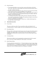
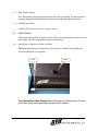
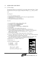
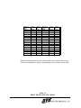
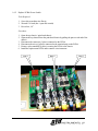
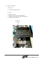
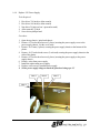
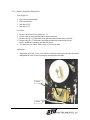
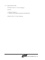
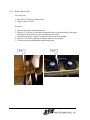
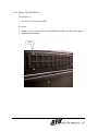
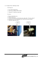
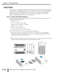
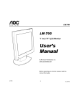
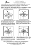
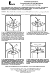
1.0
MAINTENANCE AND REPLACEMENT OF PARTS
1.1
GENERAL DESCRIPTION
The Imager is precisely aligned and adjusted at the factory for proper operation. No
mechanical or electrical adjustments are required during routine use.
Do not loosen screws marked with red lacquer. Components secured with
Marked screws have been precisely aligned at the factory using special fixtures.
Loosening the screws may cause misalignment of the components.
1.2
MAINTENANCE
To increase the reliability of the print head, the following cleaning procedure is
recommended. The use of this procedure is required to ensure continued warranty
coverage of the print head and the Imager.
1.2.1
How to Clean the Print Head
1.
2.
3.
4.
5.
1.2.2
Wear latex (non-powder) disposable gloves (OYO P/N 540V1106001).
Open 98% isopropyl alcohol cleaning wipes (OYO P/N 160V1106001).
With the cleaning wipe, rub the entire length of the print head.
After cleaning, dispose of all cleaning material. Do not reuse.
Make sure surface of print head is completely dry before closing unit.
Other Maintenance
1. The rubber platen roller and metal idler roller should be cleaned with 98% isopropyl
alcohol cleaning wipes to remove any contaminants and/or residue. All surfaces
should be completely dry before closing the unit.
2. The inside of the unit should be vacuumed and the media conditioner, if installed,
should be cleaned thoroughly before loading the next roll of media.
3. The back and side filters should be checked and cleaned if necessary to ensure good
airflow across the thermal print head.
1.2.3
Frequency of Cleaning
The thermal print head, rollers, media conditioner, and interior of the unit should be
cleaned at the end of every roll of media or sooner if required.
The back and side filters should be vacuumed or replaced monthly or sooner if necessary.
1
1.2.4
Other Precautions
•
•
•
•
•
The print head should never come into direct contact with the platen roller (black
drive roller). Either film or Mylar should be placed between the head and the roller if
no media is loaded in the imager.
The filters on the back and side of the imager should be checked and cleaned monthly
(more often if necessary) to ensure good airflow over the print head.
Do not place media or media hubs directly on floor or other unclean surface. Doing so
may cause contaminants to be picked up and introduced into the machine, which can
ultimately cause print head damage.
Avoid using the first and last wraps of media on the roll. This portion of the media
may contain contaminants due to handling. The manufacturer supplies extra media on
each roll to compensate for this procedure.
The front panel of the imager should be opened every 3 months and shavings from
the cutter removed with a vacuum.
1.3
TROUBLE SHOOTING
1.3.1
Power Failure
The power switch serves as the AC power on switch as well as circuit breaker for AC
overloads protection. The power supply is also fused for additional protection on each unit.
1.3.2
Paper Supply Failure
If the paper fails to feed properly, check for paper jams at the supply roll and in the transport
assembly. Also, check to make sure that the stepper motor is operating by pressing the
PAPER FEED (FEED/PARM-) key when the system is off line and observing the rotation
of the platen.
1.3.3
Test Pattern Failure
If the built-in test failure occurs in generating the test patterns shown in the User manual
(Fig. 4), refer to the Trouble Shooting Flow Chart on page 5 of this manual.
1.3.4
Optical Density Failure
Clean the print head as described in Sec. 1.2. Check the adjustment of power supply voltage
as described in the Sec. 1.5. If no plotted or printed image is present during execution of the
self-test function the Controller PCBA may be inoperative. If only a portion of the image is
missing, one or more of the print head nibs may be inoperative or damaged.
2
1.3.5
Data Transfer Failure
If the unit operates properly during execution of the self-test function, but does not plot or
print incoming data, check the interconnections between the unit and the data source.
1.3.6
Control Panel Failure
Consult OYO Instruments Technical Support Group.
1.4
UNIT ACCESS
This section describes how to open or remove various covers and panels to permit access to
the interior of the unit to add media or perform maintenance.
1.4.1
Entry Routes - Parts are accessible as follows:
Top Cover-Open the top cover (door) by moving the two (2) latches on top of the unit
inward and lifting the cover upward.
Lever
Latch
Top Chassis/Print Head Chassis-Open the chassis by pulling the two (2) levers
on the front of the unit forward and lifting the chassis upward.
3
To separate the upper chassis from the print head
chassis, * pull both of these pins (one at each end)
outward and the chassis will separate.
Caution: Hold the print head chassis while pulling
the pins outward so that the chassis will not fall.
* The pins will remain in the "outward" (unlocked)
position if they are rotated approx. half a turn when
pulled out.
End Covers - Remove the end covers (right or left) by
removing two (2) pan head screws securing the
cover(s) to the rear of the chassis. Gently pull the
back of the end cover outward and then slightly
forward. This should disengage the cover from the
end cover lock located in the front of the unit.
Pin
End Cover Entry
Front Cover Entry
Screw
Screw
Front Panel-Remove the front panel by first removing the two end covers (see above) and then
removing four (4) pan head screws (2 each side) securing the front panel to the chassis.
4
Begin
Self Test Failure
Checkerboard
Test
No
Press ONLINE switch
Yes
Any error on
display?
Yes
Check head open & paper out sensor.
No
Media
advances?
No
1. Check step motor belt & cable
connections.
2. Check stepping pulse on Controller
board U9-pin 6.
3. Check power supply (module 3, V3).
No
Yes
Check power supply (modules 1 and 2).
Power
supply
O.K.?
No
Correct the error
1. Check AC power.
2. Set the power supply voltage to
match the print head voltage.
1. Check print head connections.
2. Verify media is installed correctly.
No
Replace
power supply
1. Install print head connectors.
2. Install media with media coating
next to print head.
3. Make sure print head is in contact
with the media.
Yes
Begin
1. Check strobe (TH-STROBE1), J11-pin 15.
2. Check data clock (TH-CLOCK1), J11-pin 13.
3. Check latch pulse (TH-LATCH1), J11-pin 19.
4. Check data (TH-DATA0), J11-pin 1.
Are all signals
toggle?
Yes
No
Replace Controller board 614-104800
Begin
Replace print head
Begin
Trouble Shooting Flow Diagram
5
Voltage
setting
O.K.?
No
Yes
Head O.K.?
Media O.K.?
Yes
All signals
O.K.?
Yes
Yes
Begin
Begin
1.5
POWER SUPPLY ADJUSTMENT
1.5.1
24V Power Supply
The print head voltage is set to match the 24V power supply voltage at the factory. If either
the print head or the 24V power supply is changed, the voltage (V1, V2, V3 and V4) must be
reset.
Tools Required:
1.
2.
3.
4.
Screw Driver-Medium size flat tip
Alignment Tool or small flat tip screw driver (for power supply adjustment)
Digital Multimeter (+/- 0.1% accuracy)
Electrostatic Wrist Band and Anti-Foam Pad
Procedure:
1.
2.
3.
4.
5.
6.
7.
8.
Press the ON LINE switch to off-line (LED is OFF).
Press MENU to access SYSTEM MENU.
Press ITEM to FAN CONTROL.
Press CUT/PARM+ or FEED/PARM- to ALWAYS ON .
Press ENTER.
Press ON LINE; Power supply will now come on.
Remove left end cover screws in rear of plotter, remove left end cover.
Connect the RED lead of the multimeter to the V * positive (+) lead of the power
supply. Connect the BLK lead of the multimeter to the V * negative (-)]
lead of the power supply.
9. Set the volt meter to a higher voltage range than the voltage being set.
10. Using the “ PRINT HEAD VOLTAGE “ table, select the voltage which corresponds
to the print head resistance (marked on the print head).
11. Use a small screwdriver to turn the V * potentiometer on the power supply. Turn
clockwise (CW) to increase and counter-clockwise (CCW) to decrease.
12. Repeat steps 8 - 11 to adjust V2 and V3/V4.
13. Repeat steps 1 - 2.
14. Select AUTOMATIC ON/OFF
+ V1 -
V1 (nominal)
14.34V
V2 (nominal)
07.42V
V3/V4 (nominal) 05.10V
*for V1, use V1 + and V1 –
for V2, use V2 + and V2 –
for V3/V4, use V3/V4 pins 2 and 3
6
V1
Mod 1
+ V2
-
V3 V4
+ - + 1
2
3
4
V2
Mod 2
V3
Mod 3
Resistance
(Ohms)
Voltage
V1
Voltage
V2
Resistance
(Ohms)
Voltage
V1
Voltage
V2
2700
2720
2740
2760
2780
2800
2820
2840
2860
2880
2900
2920
2940
2960
2980
3000
14.84
14.89
14.94
14.99
15.04
15.10
15.15
15.20
15.25
15.30
15.35
15.40
15.45
15.50
15.55
15.60
7.42
7.44
7.47
7.50
7.52
7.55
7.57
7.60
7.62
7.65
7.68
7.70
7.73
7.75
7.78
7.80
3020
3040
3060
3080
3100
3120
3140
3160
3180
3200
3220
3240
3260
3280
3300
15.65
15.70
15.75
15.80
15.85
15.89
15.94
15.99
16.04
16.09
16.14
16.18
16.23
16.28
16.33
7.82
7.85
7.87
7.90
7.92
7.95
7.97
8.00
8.02
8.04
8.07
8.09
8.12
8.14
8.16
Find the resistance printed on the print head label in the plotter. Refer to the
chart above and find the voltage corresponding to the resistance on the label.
Table 1.1
PRINT HEAD VOLTAGE CHART
7
1.6
REPLACEMENT OF PARTS
1.6.1
Replace PCBA-Controller
Tools Required:
1. Driver-hex, 1/4”
2. Screwdriver-Medium size flat tip
Procedure:
1.
2.
3.
4.
5.
Open the top cover. (Refer to 1.4.1)
Disconnect all connectors (9 places) connected to the Controller Board.
Remove all nylon standoffs (6 places) securing the Controller Board.
Lift the Controller Board off and install the replacement unit.
All ITEM PARAMETERS are factory default. If necessary, reset the parameters as per
User manual 3.4.
Note 2
8
Note 3
1.6.2
Replace PCBA-Power Switch
Tools Required:
1. Screw driver-medium size flat tip
2. Wrench-5/16 inch (box / open end wrench)
3. Driver-hex, 1/4”
Procedure:
1. Open the top chassis / print head chassis.
2. Separate the top chassis from the print head chassis by pulling the pins at each end of the
chassis.
3. Disconnect the connector (1 place) connected to the PCBA.
4. Disconnect the wires (6 places) connected to the terminal strip on the PCBA.
5. Remove nylon standoffs (4 places) securing the PCBA to the chassis.
6. Install the replacement PCBA and reconnect wires/connector.
Note 3
9
Note 4
Note 5
1.6.3
Replace Control Panel
Tools Required:
1. Screw driver-medium flat blade
Procedure:
1.
2.
3.
4.
Open the top cover.
Remove screws (4 places) securing the panel.
Disconnect cable (connector) connected to the panel.
Install the replacement panel.
Note 2
10
1.6.4
Replace 24V Power Supply
Tools Required:
1.
2.
3.
4.
5.
Hex driver-7/64 inch (or allen wrench)
Hex driver-9/64 inch (or allen wrench)
Nut driver-3/8 inch (or box / open end wrench)
Allen wrench-5/32 inch
Screw driver-phillips head
Procedure:
1. Open the top chassis / print head chassis.
2. Remove 6-32 socket head screws (3 places) securing the power supply cover to the
power supply chassis. Set the cover aside.
3. Remove 10-32 nuts (3 places) securing the power supply chassis to the bottom of the
plotter.
4. Remove 10-32 socket head screws (2 each end) securing the power supply chassis to the
sides of the plotter.
5. Remove 8-32 socket head screws (4 places) securing the power supply to the power
supply chassis.
6. Remove wires from power supply.
7. Install the replacement power supply.
8. Replace wires to newly installed power supply.
9. Set the power supply voltage to match the print head voltage per 1.5
Note 2
Note 4
11
Note 3
Note 5
1.6.5
Replace Print Head
Tools Required:
1.
2.
3.
4.
5.
Screw driver-medium size flat tip
Screw driver-small size flat tip
3/8-nut driver
Pliers-small cutter
Multimeter - (+/- 0.1% accuracy)
Procedure:
1.
2.
3.
4.
5.
Release the print head chassis from top chassis. Refer to 1.4.1.
Disconnect three (3) wires at terminals 1, 3 and 5 of the Power Switch PCBA.
Cut tie wrap (cable tie) securing the wires to the print head.
Disconnect print head connectors CN1 and CN2.
Remove four (4) nuts securing the print head to the chassis. Caution: Hold the print
head securely to prevent it from falling out of the print head chassis.
6. Install the replacement print head using the same hardware (nuts/washers). Do not
yet tighten the nuts.
7. Close the print head chassis. Make sure the print head is in contact with the platen.
8. Open the top cover. Tighten the two (2) rear nuts all the way. Tighten the two (2)
front nuts all the way and, then, back off (un-tighten) two (2) turns front nuts only.
The front nuts are left slightly loose to permit thermal expansion of the head.
Set the power supply voltage to match the print head voltage per 1.4
12
Note 2
Note 5
Note 8
Note 3
Note 4
Note 8
1.6.6
Replace Step Motor-Platen Drive
Tools Required:
1.
2.
3.
4.
Screw driver-standard flat
Pliers-small cutter
Nut driver-5/16”
Nut driver-3/8”
Procedure:
1.
2.
3.
4.
Remove the left end cover. Refer to 1.4.1.
Cut the cable tie wrap and disconnect motor connector.
Remove the (4) 10-32 nuts that secure the motor/bracket and remove the belt.
Remove the (4) 6-32 flat head screws that assemble the motor bracket to the
motor. Install motor bracket onto the new motor.
5. To replace the new motor, follow steps 1-5 in reverse order.
Adjustment:
1. Tighten the drive belt. Use a screw driver to force the motor/motor bracket downward
and tighten the four (4) nuts securing the motor/bracket assembly.
Note 3
Note 4
13
1.6.7
Replace Platen Drive Belt
Tools Required: Refer to 1.6.6 on preceding page
Procedure:
1. Refer to 1.6.6 steps 1-4
2. Install the new belt, making sure the spacer fits inside the belt.
Adjustment: Refer to 1.6.6 on preceding page
14
1.6.8
Replace Step Motor-Cutter Drive
Tools Required:
1.
2.
3.
4.
5.
6.
Screw driver-large flat tip
Hex driver-5/64 inch (or allen wrench)
Hex driver-9/64 inch (or allen wrench)
Wrench-5/16 inch open end
Nut driver-5/16 inch (or box / open end wrench)
Pliers-small cutter
Procedure:
1.
2.
3.
4.
5.
Remove both end covers.
Remove the front cover.
Loosen screw securing the left end cutter drive belt pulley.
Remove the cutter drive belt from the motor pulley.
Remove 6-32 nuts (4 places) nuts securing the motor bracket to chassis. Take the
motor / bracket out. Note the 1/8 inch gap between the pulley and the motor face.
6. Remove 6-32 screws / nuts (4 places) securing the motor to the motor bracket.
7. Remove the pulley from the motor shaft. Install the pulley on to the new motor and set
gap at 1/8 inch, then tighten set screw securing the pulley to the motor shaft.
8. Install the replacement motor. Tighten the four (4) nuts securing the motor bracket to
the plotter firmly but do not over-tighten so as not to break the grommets.
Note 8
Note 4
15
Note 3
Note 6
Note 5
1.6.9
Replace Blower-(Fan)
Tools Required:
1. Hex driver-3/32 inch (or allen wrench)
2. Allen wrench-5/32 inch
Procedure:
1. Open the top chassis / print head chassis.
2. Remove 10-32 screws (2 each end) securing the blower air guide assembly to the print
head chassis. Remove the air guide assembly and set it aside.
3. Disconnect the power connector connected to the blower to be changed.
4. Remove 6-32 screws (4 places) securing the blower to be changed.
5. Lift the blower out and install the replacement blower.
Note 2
16
Note 4
1.6.10 Replace Filter-Fan (Blower)
Tools Required:
1. Hex driver-3/32 (or allen wrench)
Procedure:
1. Remove 6-32 screws (4 places) securing the filter bracket to the back of the plotter.
2. Install replacement filter.
Note 1
17
1.6.11 Replace Drive Cable-Paper Cutter
Tools Required:
1. Screw driver-large flat tip
2. Hex driver-1/8 inch (or allen wrench)
3. Wrench-11/32 inch box or open end
Procedure:
1.
2.
3.
4.
5.
Remove both side covers.
Remove front cover.
Loosen (do not remove) the left end cutter cable pulley. Take the cable off.
Remove the 10-32 nut securing the drive cable to the cutter assembly.
Install the replacement cable.
Note 3
18
Note 4
1.6.12 Replace Cutter Blade Assembly
Tools Required:
1. Screw driver-large flat tip
2. Nut driver-5/16
3. Nut driver-11/32
Procedure:
1.
2.
3.
4.
5.
6.
Remove both end covers.
Remove the front cover.
Remove the 10-32 nut securing the drive cable to the cutter assembly.
Remove the 10-32 shoulder screws (1 each end) securing the cutter shaft to the plotter.
Remove the cutter assembly from the cutter shaft.
Install the replacement cutter assembly. To insure the front cover clears the cutter
assembly, position the cutter assembly at least 1/8 inch (0.125) to the left of the plotter
right end chassis.
Note 4
Note 5
Note 3
19
Note 6
1.6.13 Replace Capacitor
Tools Required:
1. Allen wrench-5/32 inch
2. Pliers-cutter
Procedure:
1.
2.
3.
4.
5.
Open the top chassis / print head chassis.
Remove the screws (2 each capacitor) securing the wires to the capacitor.
Cut the tie wrap securing the capacitors to the print head chassis.
Install the replacement capacitor.
Install new tie wrap to secure capacitors.
Note 2
20
Note 3
1.6.14 Replace Switch-Media Low (SW3)
Tools Required:
1.
2.
3.
4.
5.
Screw driver-large size flat tip
Screw driver-small size flat tip
Hex driver-3/32 inch
Pliers-small cutter
Media hub-standard plastic (1 of 2 supplied with the unit)
Procedure:
1.
2.
3.
4.
5.
6.
Remove the left end cover.
Open the top chassis / print head chassis.
Cut the tie wrap securing the switch cable to the chassis.
Remove the 4-40 screws (2 places) securing the switch bracket to the chassis.
Remove the 2-56 screws (2 places) securing the switch to the switch bracket.
Install the replacement switch (with cable and connector). Do not yet tighten the two 440 screws all the way down.
Adjustment: Use one of the media hubs supplied with the unit to adjust the switch.
A. Note the indention (recess) in the media hub. Using your hand to hold the media hub,
place the hub into the left side of the unit same as though it were loaded with media.
B. Rotate the hub until the roller on the switch contact arm is in the indention. Tighten the
2 screws securing the bracket to the chassis.
C. Check the action of the switch by rotating the media hub. If the switch bracket is
adjusted correctly, the switch will turn on and off as the indention passes over the switch
contact roller.
Note 3
21
Note 4
Note A
Notes A, B, C
1.6.15 Replace Switch-Head Engaged, right and left (SW1 and SW2)
Tools Required:
1. Screw driver-large size flat tip
2. Allen wrench-5/64 inch
3. Pliers-small cutter
Procedure:
1.
2.
3.
4.
5.
Remove both end covers.
Open the top chassis / print head chassis.
Cut the tie wrap securing the cable to the chassis.
Remove the 2-56 screws (2 places) securing the switch to the chassis.
Install the replacement switch.
Note 4
22
1.6.16 Replace Switch-Platen Stall (I3)
Tools Required:
1.
2.
3.
4.
Screw driver-large size flat tip
Hex driver-3/32 inch
Nut driver-3/16 inch (or box or open end)
Pliers-small cutter
Procedure:
1.
2.
3.
4.
5.
Remove right end cover.
Cut the tie wrap securing the cable to the chassis.
Remove the 4-40 screws (2 places) securing the switch bracket to the chassis.
Remove the 4-40 screws (2 places) securing the switch to the switch bracket.
Install the replacement switch.
Note 3
23
1.6.17 Replace Sensor-Paper Cut, right and left (I1 and I4)
Tools Required:
1.
2.
3.
4.
5.
Screw driver-large size flat tip
Screw driver-small size flat tip
Hex driver-1/4 inch
Nut driver-5/16 inch
Pliers-small cutter
Procedure:
1.
2.
3.
4.
5.
6.
Remove right and left end covers.
Remove front cover.
Cut the tie wrap securing the cable to the chassis.
Remove the 4-40 screws (2 places) securing the switch bracket to the chassis.
Remove the 4-40 screws (2 places) securing the switch to the switch bracket.
Install the replacement switch.
Note 4
24
Note 5
1.6.18 Assembly of Long Knife
Tools Required:
1.
2.
3.
4.
Screwdriver-standard, Medium flat tip
Hex driver-5/16
Allen driver-5/32, 5/64
Open end wrench-5/16
Procedure:
1. Remove the left and right end covers by removing the 10-32 screws, located on the
rear of the plotter. (2 ea. side)
2. Open upper chassis. (Refer to 1.4.1)
3. Remove the 10-32 hex head screws (1 ea. side) that hold the long knife assembly into
the plotter.
4. Remove the 6-32 flat head cap screws that hold the long knife blade onto the
stiffener. Important: Do not rotate blade end for end. Rotate blade front-to-back or
back-to-front and reassemble onto the stiffener. The proper operating angle is shown
in the end view illustration below.
5. Reinstall long knife blade assembly into the plotter. Center the assembly by it about
1/2” from the inside surface of the plotter ends as shown in the illustration below.
Note 5
1.6.19 Replacement of Long Knife
Tools and Procedure (Refer to 1.6.18)
25
Note 4
1.6.20 Cleaning or Changing the Media Conditioner
The media conditioner should be cleaned at the end of every roll of media or sooner if
required and should be replaced at the end of every ten (10) rolls of media.
•
•
•
•
•
•
•
•
Open the chassis for access to the roll media.
Locate the lever on the right side of the media conditioner bar.
Lift the lever upward so that the media conditioner bar may be rotated.
Pull the media cleaning sock apart at the seam (the sock is attached to the roller with
Velcro) and remove it from the bar.
Place the media cleaning sock on a clean, flat surface and vacuum it until it is clean or
replace it with a new one.
Place the media cleaning sock on the bar with the seam facing upward. When the sock
is secure, rotate the bar until the seams meet.
Move the lever back to the closed (downward) position to lock the bar in place. The
seam should be facing upward.
Vacuum out any particles of Velcro material. A new roll of media may now be
installed.
Lever in closed position
Lever in open position
Vacuum the media cleaning sock
26