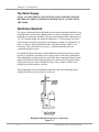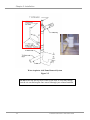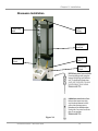
1
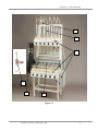
User’s Manual
Open Combination (Macro)
Kjeldahl Systems
Models
21232 Series
21233 Series
21236 Series
21237 Series
To receive important product updates,
complete your product registration card
online at register.labconco.com
Labconco Corporation
8811 Prospect Avenue
Kansas City, MO 64132-2696
800-821-5525, 816-333-8811
FAX 816-363-0130
E-MAIL [email protected]
HOME PAGE www.labconco.com
Please read the User’s Manual before operating the equipment.
Copyright © 2010 Labconco Corporation. All rights reserved.
The information contained in this manual and the accompanying products are copyrighted and all
rights reserved by Labconco Corporation. Labconco Corporation reserves the right to make periodic
design changes without obligation to notify any person or entity of such change.
Warranty
Labconco provides a warranty on all parts and factory workmanship. The warranty includes areas of
defective material and workmanship, provided such defect results from normal and proper use of the
equipment.
The warranty for all Labconco products will expire one year from date of installation or two years
from date of shipment from Labconco, whichever is sooner, except the following;
•
•
•
•
•
Purifier® Logic® Biological Safety Cabinets and PuriCare® Lab Animal Research Stations
carry a three-year warranty from date of installation or four years from date of shipment from
Labconco, whichever is sooner.
SteamScrubber® & FlaskScrubber® Glassware Washers carry a two-year warranty from date
of installation or three years from date of shipment from Labconco, whichever is sooner.
Blood Drawing Chairs carry a ten year warranty.
Carts carry a lifetime warranty.
Glassware is not warranted from breakage when dropped or mishandled.
This limited warranty covers parts and labor, but not transportation and insurance charges. In the
event of a warranty claim, contact Labconco Corporation or the dealer who sold you the product. If
the cause is determined to be a manufacturing fault, the dealer or Labconco Corporation will repair or
replace all defective parts to restore the unit to operation. Under no circumstances shall Labconco
Corporation be liable for indirect, consequential, or special damages of any kind. This statement may
be altered by a specific published amendment. No individual has authorization to alter the provisions
of this warranty policy or its amendments. Lamps and filters are not covered by this warranty.
Damage due to corrosion or accidental breakage is not covered.
Returned or Damaged Goods
Do not return goods without the prior authorization from Labconco. Unauthorized returns will not be
accepted. If your shipment was damaged in transit, you must file a claim directly with the freight
carrier. Labconco Corporation and its dealers are not responsible for shipping damages.
The United States Interstate Commerce Commission rules require that claims be filed with the
delivery carrier within fifteen (15) days of delivery.
Limitation of Liability
The disposal and/or emission of substances used in connection with this equipment may be governed
by various federal, state, or local regulations. All users of this equipment are required to become
familiar with any regulations that apply in the user’s area concerning the dumping of waste materials
in or upon water, land, or air and to comply with such regulations. Labconco Corporation is held
harmless with respect to user’s compliance with such regulations.
Contacting Labconco Corporation
If you have questions that are not addressed in this manual, or if you need technical assistance, contact
Labconco’s Customer Service Department or Labconco’s Product Service Department at 1-800-8215525 or 1-816-333-8811, between the hours of 7:00 a.m. and 6:00 p.m., Central Standard Time.
Part #2081400, Rev. U
ECO G001
TABLE OF CONTENTS
CHAPTER 1: INTRODUCTION
Components Shipped
General Description
Performance
Component Identification
1
1
2
3
3
CHAPTER 2: INSTALLATION
General Installation Notes
Location
Electrical
Tap Water Supply
Distillation Manifold
Water Aspirator Exhaust System
Acid Fume Blower Exhaust System
Blower Airflow Exhaust Volume Requirement & Velocity Test
Digestion Rack Drip Shield
Glassware Installation
6
6
6
7
8
8
9
11
11
12
13
CHAPTER 3: NORMAL OPERATION & ROUTINE
MAINTENANCE
Normal Operation Start-Up
Clean-Up and Cosmetic Guidelines
Fume Removal Manifold Suction Adjustment
Exhaust Systems Maintenance
Drip Shield
14
14
15
15
15
16
APPENDIX A: REPLACEMENT PARTS
17
APPENDIX B: DIMENSIONS & AIRFLOW REQUIREMENTS 19
APPENDIX C: TOTAL KJELDAHL NITROGEN METHOD
20
Chapter 1:
Introduction
Components Shipped
Carefully check the contents of your Open Combination Kjeldahl System for
shipping damage while it is still on the shipping pallet. Do not discard the
packaging material until the contents have been checked and the equipment
has been approved for installation.
The Open Combination Kjeldahl Nitrogen System has been shipped in one
complete crate to minimize damage that may occur in transit.
Make sure to inspect the product thoroughly prior to installation and report
any damage that may have occurred in transit (see Warranty page for
instructions).
Figure 1-1
Product Service 1-800-522-7658
1
Chapter 1: Introduction
General Description
Labconco’s Open Combination (Macro) Kjeldahl Nitrogen System is
designed to facilitate the determination of Total Nitrogen content within
materials such as feeds, grains, soils, fertilizers, plant tissue, water, organic
wastes, and food products. The expression ‘Macro’ identifies the size of
sample vessel and the sample size that can be used with this equipment.
Other Kjeldahl systems are available, which use smaller sample vessels and
require smaller sample sizes. The apparatus can be used for the digestion
and/or distillation of all types of nitrogen containing samples. The system
consists of the Lower Digestion rack and Upper Distillation rack. Both are
used in standardized (Macro) Kjeldahl Nitrogen Determination Methods.
This Kjeldahl system is not enclosed, excess heat and personnel safety during
the digestion and distillation reactions should be considered when selecting
an installation location. High temperature acid digestion and caustic
distillation comprise the two-step Kjeldahl Nitrogen determination method.
2123202 Six Place Open Combination Macro-Kjeldahl System
2
Product Service 1-800-522-7658
Chapter 1: Introduction
Performance
The Open Combination Kjeldahl Digestion and Distillation Systems have
been designed for use in the determination of nitrogen (or ammonia)
concentrations. By calculation nitrogen can be converted to protein values for
products such as plant tissues, meats and other food substances. Nitrogen
determinations with the Open Combination (Macro) Kjeldahl Systems can
accommodate sample sizes up to 5 grams due to the size of the
digestion/distillation flasks. However, higher levels of organic content within
a specific sample type will require smaller sample sizes due to the vigorous
digestion reaction. Detailed procedures developed by professional laboratory
organizations such as American Association of Analytical Chemists (AOAC)
and American Association of Cereal Chemists (AACC) should always be
consulted for step by step analytical procedures when operating this
equipment. For methodology precision and accuracy please consult the
specific published method for the type of sample or substance that will be
analyzed.
Component Identification
1. Electric Heaters. 600-watt heaters are used in both the lower digestion
and upper distillation rack of the unit. Infinite control switches regulate
each of the heaters. The curved heater elements are provided and allow
for the round base of the Kjeldahl Flasks, providing faster and more
evenly distributed heat. The heating element assembly on the digestion
rack can be moved closer to or away from the acid fume removal
manifold to accommodate different size Kjeldahl flasks. All heaters and
temperature controllers are wired to a common electrical box for
connection to a facility electrical service.
2. Lower Fume Removal Manifold. Located in back of the digestion
heater elements, this manifold is manufactured from chemical resistant
chlorinated polyvinyl chloride and fitted with heat resistant Teflon®
nipples designed to prevent leakage of the hot sulfuric acid fumes created
during the digestion process. The nipple design, extends in to the flask
opening, and efficiently removes excess acids fumes during the digestion
process. The flasks are oriented at a 45 degree angle to the fume removal
manifold to promote the condensation and refluxing of the acid fumes
back down into the digestion flask. This refluxing process prevents the
samples from boiling dry during the 45+ minute digestion process.
Component features #3 or #4 are selected by the customer when the
product is ordered. The Kjeldahl units described in this manual
feature either the blower exhaust or water ejector exhaust system to
remove the digestion fumes through the fume manifold system.
®
Teflon is a registered trademark of E. I. du Pont de Nemours and Company or its affiliates.
Product Service 1-800-522-7658
3
Chapter 1: Introduction
3. Acid Fume Blower Exhaust System. Located on the left side of the
unit, this blower removes excess sulfuric acid fumes from the digestion
flasks. The blower is direct-drive with corrosion resistant impeller wheel.
The blower draws the sulfuric acid fumes through the CPVC digestion
manifold and discharges the fumes under positive pressure out through a
duct work system connected to the buildings exterior. The 6" exhaust
stack of the blower must be connected to a leak-tight PVC ductwork
system that vents 10 ft (3 meters) above the building roof.
4. Acid Fume Water Aspirator Exhaust System. A water aspirator fume
removal system located on the left side of the digestion fume manifold is
alternatively available on Kjeldahl systems. The water aspirator draws
excess acid fumes by producing a vacuum in the digestion manifold and
the flask nipples. The acid fumes are dissolved in the water and flushed to
a 3-inch drain connection. The water ejector includes an air-vent pipe
connection, which must to ducted to the roof of the building. The vent
pipe prevents an air-lock from occurring within the water aspirator. The
water aspirator requires a 3/4" NPT water connection with 60 psig and 68 gallons per minute flow rate in order to operate.
5. Temperature Gauge The condensation rack behind the upper distillation
heating elements requires cooling water. The temperature of the
distillation cooling water can be adjusted to promote condensation and
suit individual requirements with the flow control valve handle, located
below the distillation heaters. Water temperature is indicated on the
thermometer, which is located at the water outlet of the distillation
manifold. The water connections are 3/4" NPT and the supply line should
be 1/2" minimum for proper water flow through the unit. For facilities
where the ground water temperature exceeds 80°F (27°C), a recirculation
water chiller system will be required to achieve sufficient condensation
results.
6. Distillation Condensation Manifold Epoxy coated steel outer columns
with stainless steel inner condensation columns provide long life. Each of
the six column manifold features 3/4" NPT tap water inlet and outlets for
easy plumbing connections.
4
Product Service 1-800-522-7658
Chapter 1: Introduction
5
6
1
4
3
2
Figure 1-2
Product Service 1-800-522-7658
5
Chapter 2:
Installation
General Installation Notes
The Open Combination Macro-Kjeldahl System is shipped fully assembled.
Exhaust duct work, electrical service, water supply and drain connections should
be completed by a licensed contractor.
The customer will need to purchase their preferred size of Kjeldahl Flasks, with
one-hole-rubber-stoppers and distillate receiving flasks. The glass Connecting
Bulbs and Delivery Tubes are provided with each Kjeldahl System.
Figure 2-1
Connecting Bulbs and Delivery Tubes
are included with Macro Kjeldahl Systems.
For installation of the Connecting Bulbs
and Delivery Tubes see section on Glassware
Installation and Figure 2-8.
Use caution when you remove the protective packaging material taped to the
heater runways as fragile components are involved. Levelers are shipped
installed, as are the distillation cooling water thermometers.
Location
If possible, the apparatus should be uncrated in the room in which it is to be
placed. Open Combination Macro-Kjeldahl Systems are heavy and can not be
disassembled to reduce their overall size. Special arrangements should be made in
advance for moving the systems to their final location within a facility. Special
instruction tags are attached to the apparatus; they must not be removed until the
installation has been completed.
The Open Combination Kjeldahl System does not include a safety enclosure.
Labconco advises installing this Kjeldahl in a location segregated away from
normal Laboratory personnel traffic. High heats along with boils acids and
caustics present a safety hazard to personnel in close proximately to the Open
Combination Kjeldahl System. Labconco also recommends spot exhaust
ventilation for the final installation location to remove excess heat produced by
the Kjeldahl digestion and distillation heaters.
6
Product Service 1-800-522-7658
Chapter 2: Installation
Electrical
Open Combination Macro-Kjeldahl Systems have been wired at the factory per
the product model number ordered by the customer. Labconco model numbers
ending in 01 are 115 volts. Model number ending in 02 are 230 volts. Models
ending in 03 are 230 volt, three phase. Amperage requirements vary depending on
the number of heaters per the digestion rack. The tables below provide the voltage
and amperage electrical requirements for the Open Combination Macro-Kjeldahl
Systems. A qualified electrician will need to connect the facility electrical supply
to the main breaker box with its individual circuit breakers. The following basic
steps should be followed:
1. Remove circuit breaker box cover panel.
2. Main line lead connection terminals are identified and connections
must be made accordingly.
3. Line leads to the apparatus must conform to local electrical codes.
4. Provide an electrical ground to the apparatus per code.
5. Before applying power to apparatus, check the electrical panel and
breakers for loose connections.
6. Reinstall box cover panel.
7. Power the breaker box and reset breakers to check circuits in the
apparatus.
8. All electrical wiring and connections must conform to local codes and
should be performed by qualified electricians. An earth ground must
be provided.
Figure 2-2
Product Service 1-800-522-7658
7
Chapter 2: Installation
Tap Water Supply
NOTE: ALL PLUMBING CONNECTIONS AND COMPONENTS MUST
BE FREE OF FOREIGN MATERIAL BEFORE FINAL CONNECTIONS
ARE MADE.
Distillation Manifold
The Open Combination Macro-Kjeldahl Systems feature an upper distillation rack
with individual condensation columns, these are connected together by a common
manifold (6 columns per manifold). The tap water inlet and outlet connections are
3/4" NPT and the supply line should be minimum 1/2" ID for proper water flow
and heat removal capacity through the condensation columns (6-8 gallons/23-30
liters per minute). Open Combination Macro-Kjeldahl Systems with 12 or 18
heaters per rack will include two or three, 6 column manifolds which are
connected together in series.
The plumbing line for the outlet of the distillation manifold must be free of back
pressure to avoid flow restriction of the cooling water. If the Open Combination
Macro-Kjeldahl is equipped with the Acid Fume Water Aspirator Exhaust System
option, the distillation water drain should not be connected to the aspirator drain.
Unless provisions are made to handle the larger water volumes without water
backing up over the aspirator vent line.
Water discharged from the distillation manifold is not acid contaminated and
standard drain lines may be used for its removal.
Distillation Manifold Tap Water Connections
Figure 2-3
8
Product Service 1-800-522-7658
Chapter 2: Installation
Water Aspirator Exhaust System
Figure 2-4
For models with a Water Aspirator
For correct operation, the water aspirator’s 3/4" NPT connection must be
connected to a 3/4" supply line with a minimum of 60 psi line pressure.
The water aspirator system is sized for use with a nominal 3" dia. line. The
aspirator discharge pipe terminates with a 3" dia. PVC coupling to drain and a 11/2" dia., 45° vent coupling for connection to an air roof vent. The discharge
drain for the aspirator must be acid proof, the discharge water will be acidic. The
drain should be capable of carrying up to 6 gpm (23 lpm) of discharge without
backing up over the 45° air vent connection on the aspirator. See plumbing
diagram.
The 1-1/2" dia. vent line must be vented to the roof, which prevents an airlock
from occurring within the fume removal manifold and prevent back pressure from
building up within the aspiration system. This vent must be acid resistant
material; acid fumes will be exhausted to the outside through this vent line.
As previously mentioned the drain line must be free of back pressure to prevent
closing of the atmosphere vent and stopping the removal of the acid fumes
through the manifold. The drain on the water ejector system should be a sealed
installation to avoid fumes in the laboratory.
Inside the water aspirator, the position of the water nozzle relative to the fume
manifold is factory set and should not require field adjustments for normal
conditions. Care should be taken to maintain this “set” position when connecting
the water line to the aspirator and should be checked periodically to be maintained
in optimum working condition.
Product Service 1-800-522-7658
9
Chapter 2: Installation
Water Aspirator Acid Fume Removal System
Figure 2-5
Do not locate trap directly below water ejector stub, or water may backup
into the air vent and stop the fume removal through your exhaust manifold.
10
Product Service 1-800-522-7658
Chapter 2: Installation
Acid Fume Blower Exhaust System
The exhaust duct connection on top of the blower is sized for use with 6" nominal
(6-5/8" O.D.) vent duct. The blower assembly is supplied with a short piece of 6"
PVC pipe and a flexible coupling with clamps to connect the blower housing
assembly to the duct work exhaust stack.
Joints under the flexible coupling must be sealed with an acid-resistant sealant
(silicone or acid resistant cement) before tightening clamps to prevent leakage of
acid condensate at this point.
Flexible
Coupling
A
Sealant
PVC
Coupling
Acid
Condensate
Drain Tube
Figure 2-6
The bottom of the blower housing is fitted with a condensate drain and corrosion
resistant tubing. This condensate (identified by “A” above and on the next page)
can be collected in a closed acid proof container, which should be emptied
regularly or it may be plumbed to an acid resistant drain line. The condensate is
concentrated acid and care must be exercised when handling it.
Blower Airflow Exhaust Volume Requirement &
Velocity Test
Cubic feet per minute = 25
Average airflow velocity = 117 feet per minute
The Kjeldahl’s blower airflow volume test is based on the "Pitot Traverse in Inlet
Duct" method described in the ANSI/ASHRAE 51-1999 standard. Duct velocity
measurements are taken at 48" from the blower using a 6 point duct traverse
pattern (Industrial Ventilation 24th Edition p. 9-10).
Product Service 1-800-522-7658
11
Chapter 2: Installation
(Duct Area in Square Feet) x (Average Airflow Velocity in feet per minute)
= (Air Volume CFM)
(Pi) radius² X 117 FPM = 25 CFM
The exhaust stack rising from the blower exhaust connection must be vented to
the outside atmosphere. A 6" diameter duct is sufficient for carrying the fumes a
distance not exceeding 60 feet. In estimating the duct length count each 90°
elbow as 12 feet and add to the straight length total of duct for the duct system. If
the duct system exceeds 60 feet in equivalent length, it may be necessary to
increase the duct size to compensate for the friction loss generated by this
additional length.
WARNING: Acid resistant duct must be used on the exhaust connection on
your Kjeldahl Apparatus.
Highly corrosive fumes produced from boiling sulfuric acid will flow through
the ductwork, so acid-resistant duct must be used. Polyvinyl chloride (PVC)
or fiberglass duct is recommended. The exhaust duct work must be supported
independent of the Kjeldahl System to avoid distortion of the blower housing.
Digestion Rack Drip Shield
The digestion heaters are located in a drip shield and constructed of stainless steel
which is resistant to acid attack. Liquid acid spills that occur can be drained to an
acid resistant container with the drip tube located on the left side of the digestion
rack.
Blower Acid Drip Tube
and
Digestion Rack Drip Tube
Figure 2-7
12
Product Service 1-800-522-7658
Chapter 2: Installation
Glassware Installation
Connecting
Bulb
Rubber
Tubing
Distillation
Manifold
Delivery
Tube
Distillation
Flask
Receiving
Flask
Figure 2-8
Product Service 1-800-522-7658
13
Chapter 3:
Normal Operation & Routine
Maintenance
Normal Operation Start-Up
1. The KNA apparatus is designed for use with either 500 or 800-ml
Kjeldahl Flasks. The digestion heaters are free to move forward or
backward on the runway to accommodate either size flask.
2. Turn the heat controllers to the setting on both the Digester and
Distillation racks if both racks will be used simultaneously. Wait
approximately 5 to 10 minutes to insure proper preheating. Sample
chemistry limits the boiling temperature of the sample, so the high heat
setting may be used.
3. Start the acid fume removal blower or water aspirator (depending on
model number purchased). Place a small piece of tissue paper over the
nipple on the digestion manifold. Suction should be
sufficient to hold 2" x 2" (51 mm x 51 mm) tissue paper
in place.
4. Begin the distillation cooling water and check for leaks.
For correct operation of the condensers, the temperature
of the cooling water should not exceed 80°F (27°C).
Watch your thermometer and regulate water flow by
the control valve
5. The inner stainless steel condensing tubes on the
distillation apparatus should be rinsed out by boiling
nitrogen free water in Kjeldahl flasks attached to the
condensation columns before commencing a distillation
procedure.
A generalized Kjeldahl Total Nitrogen method is present in
Appendix C. The method does not detail sample
preparation or preservation procedures, which may be
required depending on specific types of samples.
14
Product Service 1-800-522-7658
Chapter 3: Normal Operation & Routine Maintenance
Clean-Up and Cosmetic Guidelines
•
•
•
Keeping the Open Macro Kjeldahl System clean will preserve the
appearance and improve life of the equipment.
The equipment can be kept clean by washing with a weak solution of
sodium hydroxide and rinsing with clear water.
Sulphate, a salt of Sulfuric Acid, may build up between the channel
support and the fume removal manifold. Neutralize this with a weak
solution of sodium hydroxide periodically to keep the unit clean.
Fume Removal Manifold Suction Adjustment
The suction along the fume removal manifold is adjusted as follows:
Water Aspirator Exhaust System
Suction is adjusted by changes in the water supply flow rate. The suction
may be decreased by reducing the flow rate.
Blower Exhaust System
No adjustment is required on the suction pressure at the manifold when used.
The blower fan should be inspected annually for debris and proper operation.
Exhaust Systems Maintenance
Sometimes the suction in the nipples is reduced due to obstruction within the
exhaust system. These obstructions can usually be washed from the fume
pipe, blower housing or water ejector by boiling water in a number of flasks
placed on the digestion heaters. The blower or water aspirator should be in
operation to draw the steam through the fume pipe.
The direct drive motor should be lubricated in accordance with the
manufacturer’s recommendations for heavy-duty usage by adding appropriate
minimal drops of S.A.E. 10 automotive type oil annually or at least every
1500 hours of operation.
CAUTION: Do not oil excessively!
Product Service 1-800-522-7658
15
Chapter 3: Normal Operation & Routine Maintenance
Drip Shield
The drip shield is constructed of stainless steel and is resistant to most acid
attack. Acid spills can however cause discoloration and eventual marring of
the surface unless the following proper procedures are followed in their clean
up.
1. Promptly wash down all major acid spills contained by the shield.
2. Periodically clean the stainless surface with any residential stainless
steel sink cleaning compound.
3. After cleaning, renew the bright shiny appearance by lightly sanding
with 220 grade emery paper.
16
Product Service 1-800-522-7658
Appendix A:
Replacement Parts
Electrical Heaters and Motor/Blower Parts
Part Number
Description
1315400
1315500
2011500
2023200
2033100
2033200
2023100
2031800
1870200
1317100
1850500
2053900
1200000
1203200
1203600
1851800
2054500
1451300
2056600
2055400
2055500
1851100
2053000
1967000
2144600
1662200
2165800
1880128
2164000
Heater Control, Infinite (115Volts)
Heater Control, Infinite (230Volts)
Core Plate Casting, (package of 6)
Heater Base Casting (electric or gas)
Heater element, 115V, 600 W, (package of 6)
Heater element, 230V, 600 W, (package of 6)
Heater Top ceramic casting (electric or gas)
Heater lead wire assembly, (package of 6 pairs)
Knob for Infinite Heater Control
Blower Motor Switch
Adjustable sheave (pulley) for belt drive blower only
Blower housing assembly (plastic housing only)
Blower motor 1/3 H.P., 115V, 60 Hz
Blower motor 1/3 H.P., 230V, 60 Hz
Blower motor 1/3 H.P., 230V, 50 Hz
Blower shaft bearing (belt drive only)
Blower bearing assembly
Blower wheel
Ceramic nipple
Cover, blower wheel
Blower Shaft (belt drive only)
V-belt (drive only)
Water ejector nozzle
Clamp, hose
Flex sleeving
Grommet 1/2 ID x 1-1/2 OD
Teflon nipple
Plastic screws for Teflon nipple
Motor shield
Product Service 1-800-522-7658
17
Appendix A: Replacement Parts
Miscellaneous Replacement Parts
Part Number
1620500
2152402
2038800
2038900
2031700
2146400
2081300
2128800
2078800
18
Description
Tubing, rubber condenser connecting, per foot
Distillation manifold – 6 place stainless steel
Wire, No 14 Black, SEWF-2, 30 ft length
Wire No. 14 White, SEWF-2, 30 ft length
Heater terminal assembly, package of 24
Assembly inlet & outlet manifold (12 unit only)
Connector bulb/caustic trap, package of 6
Delivery tube, package of 6
Kit, replacement fume pipe to blower housing
Product Service 1-800-522-7658
Appendix B:
Dimensions & Airflow
Requirements
B-1
Product Service 1-800-522-7658
19
Appendix C:
Total Kjeldahl Nitrogen Method
Titrimetric Determination
Various scientific associations offer approved Kjeldahl methods. These
methods are available at their websites. The AOAC International (Official
Methods of Analysis), Association of American Cereal Chemists (Approved
Methods), American Oil Chemists Society, Environmental Protection Agency
(EPA Methods for Chemical Analysis of Water and Wastes), International Standards
Organization, The National Forage Testing Association, and United States
Department of Agriculture.
This methodology is for reference only. It is not a citable document. It is
based on data we believe to be reliable. It is offered in good faith but without
guarantee.
1. Scope and Application
1.1. This method determines the Total Kjeldahl Nitrogen (TKN) in water,
and organic substances. There are three steps within the method: 1.
the digestion procedure – which converts organic nitrogen to
ammonia, 2. the distillation procedure - transferring ammonia from
the digested sample to an ammonia trapping solution 3. sample
titration – the quantification of ammonia in the trapping solution.
NOTE 1: Some compounds containing nitrogen may not be converted;
such as amines, nitro-compounds, hydrazones, oximes,
semicarbazones and some tertiary amines.
1.2. This method is described for use with Kjeldahl equipment using
Macro-Size glassware (500 - 800 ml flasks).
2. Definitions
2.1. TKN is defined as the sum of free-ammonia and organic nitrogen
compounds, converted to ammonium sulfate (NH4)2SO4 by acid
digestion.
3. Apparatus
3.1. Digestion Apparatus: A Kjeldahl digestion apparatus with multiple
600 watt electric burners, using 500 - 800 ml flasks and a fume
removal manifold system.
3.2. Distillation Apparatus: A Kjeldahl distillation apparatus with
multiple 600 watt electric burners, using 500 - 800 ml flasks. The
distillation system includes connecting bulbs to prevent mechanical
carryover of NaOH during distillation, water cooled condensers and
20
Product Service 1-800-522-7658
Appendix C: Total Kjeldahl Nitrogen Method
distillate receiving vessels, such as 250 ml Erlenmeyer flasks. The
equipment is available as a combined system, featuring both
digestion and distillation apparatus. The preheated burners should
bring 250 ml of water at 25° C to a rolling boil with in 5 minutes.
Condensation columns should cool distillate to 75° F (23.8°C).
3.3. Titration Class A Burets, 25-50 ml. for dispensing Standardized Acid
solution.
3.4. Analytical balance, sensitive to 0.0001grams.
4. Reagents
4.1. Purified water, nitrogen free.
4.2. Sulfuric acid, H2SO4 concentrated, Specific Gravity of 1.84. (9598%, nitrogen free)
4.3. Copper sulfate, CuSO4, anhydrous. Nitrogen free. (catalyst)
4.4. Potassium sulfate, K2SO4. Nitrogen free. (boiling point elevator)
4.5. Sodium hydroxide NaOH, reagent grade Specific Gravity 1.3,
nitrogen free. 45% solution, (dissolve pellets, 450g NaOH in distilled
water and dilute to 1 liter).
4.6. Boiling stones, Antibumping agent, aluminum oxide stones, (Hengar
granules).
4.7. Mixed color indicator: 0.75 g of Methyl Red and 0.5 g Methylene
Blue in 300 ml of 95% ethanol. (Prepare fresh every 30 days)
4.8. Boric acid H3BO3, saturated solution, (dissolve granules, 40 g boric
acid, in purified water and dilute to 1 liter). Add 3 ml of the mixed
color indicator solution to the 1 liter of boric acid solution.
4.9. Sulfuric acid, H2SO4, standardized solution: (0.02 N) Prepare a stock
solution of approximately 0.1 N sulfuric acid by diluting 3 ml of conc.
H2SO4 (sp. Gr. 1.84) to 1 liter with CO2-free distilled water. Dilute 200
ml of this solution to 1 liter with CO2-free distilled water.
Alternatively, premade standardized acid and base solutions with a
certified specification ranges are commercially available through most
Scientific Equipment Dealers. If the Sulfuric Acids standard solutions
are prepared, their normality must be determined analytically.
5. Digestion
5.1. The distillation condensation columns should be cleaned before use
by distilling a 1:1 mixture of distilled water and sodium hydroxide
until the distillate is ammonia-free. Then repeat this cleaning
procedure if the apparatus is out of service long enough to
accumulate ammonia (> 4 hours).
5.2. Digestion
5.2.1.
Place a homogenous measured sample (0.250 – 1.000
gram) into a 500 - 800 ml Kjeldahl flask. Weigh or
measure the sample to the nearest 0.1 mg/ml.
5.2.2.
Add to each flask:
20 ml sulfuric acid, 0.04 g CuSO4, 15g K2SO4 potassium
sulfate, 8-10 boiling stones. Place flask on the digestion
burner in inclined position (promotes acid refluxing), with
Product Service 1-800-522-7658
21
Appendix C: Total Kjeldahl Nitrogen Method
the flask neck on the fume removal system. If necessary
lower the burner heat setting to prevent sample from
foaming up into neck of flask. Once, the sample comes to
a smooth rolling boil return heat setting to maximum.
When digestion sample clears (no black specs with pale
green tint color), continue to boil for an equal length of
time as required to reach the clear point, (total time
approx. 1 hr). If black specs occur in the flask neck, rotate
the flask 180 degrees to allow refluxing acid to rinse the
internal flask surface. Allow digestion mixture to cool and
carefully add 50 ml of distilled water to prevent K2S04 salt
solids from forming. All salt crystals must be dissolved
before proceeding to the next step. If necessary partially
reheat sample and agitate to dissolve crystals.
6. Distillation
6.1. The distillation burners should be preheated and condenser cooling
water turned on. The receiving flask should be in-place with enough
boric acid H3BO3 plus the mixed indicator solution to submerge the
tip of condenser delivery tube well below the level of the boric acid
receiving solution in the receiving flask. (Erlenmeyer 250 ml flasks
recommended)
6.2. In a fume hood, carefully adding of 100 ml of 45% sodium
hydroxide solution without mixing to make the digested sample
alkaline. Tilt the flask in to the hood while adding the sodium
hydroxide to the sulfuric acid digestion solution. Slowly add the
heavy sodium hydroxide solution down the neck of the flask. The
heavier sodium hydroxide solution will slip under the aqueous
sulfuric acid solution without mixing and with out loss of freeammonia. Do not mix until the flask has been connected to the
distillation apparatus.
6.3. Immediately connect the flask to a condenser using the rubber
stopper on the distillation connecting bulb attached to a condenser
column.
6.4. Vigorously swirl the Kjeldahl flask to mix contents thoroughly; heat
until all NH3 has been distilled (>8-10 minutes). During the ammonia
transfer the receiving solution with change color from purple to
green. Lower receiving flask and let liquid drain from condenser tip.
Turn off distillation burners.
6.5. For nitrogen concentrations above 1 mg/1, the ammonia can be
determined titrimetrically. For concentrations below this level,
colorimetric or potentiometric determination methods are
recommended.
22
Product Service 1-800-522-7658
Appendix C: Total Kjeldahl Nitrogen Method
7. Titration
7.1. Depending on the samples expected nitrogen level and the sensitivity
of the titration desired, select the appropriate standardized H2SO4
solution (0.02 or 0.10 normal). High or low nitrogen concentrations
will require standardized H2SO4 solutions with stronger or weaker
normalitys. Titrations should require at least 15 ml of titrant to be
accurate. Fill a class A. buret to the zero line with the standardized
H2SO4 solution. Titrate the H3BO3 receiving solution with
standardized H2SO4 solution to first trace of the original purple
color. A white stirring plate will aid color visualization of end
point. Record ml H2SO4 titrated to the at least nearest 0.05 ml. Match
the endpoint against a sample blank containing the same volume of
distilled water and H3BO3 solution.
8. Calculation
For Dry Samples% Nitrogen =
% Nitrogen, = (ml H2SO4, sample - ml H2SO4, blank ) x Normality H2SO4 x
1.4007/ weight of sample in grams. (1.4007 = a single factor that takes into
account the molecular weight of Nitrogen, the conversion of milli-equivalent results of
V*N, and the conversion to %)
% Nitrogen, = (ml H2SO4, sample - ml H2SO4, blank) x normality H2SO4 x
1400.7 x 100/ weight of sample in milligrams.
For Liquid Samples: calculate Total Kjeldahl Nitrogen, in mg/1, in the
original sample as follows:
Milligrams Total Nitrogen per Liter = (ml H2SO4, sample - ml H2SO4,
blank) x normality H2SO4 x 14.007x 1000/ volume of sample in milliliters.
If desired to determine % protein instead of % nitrogen, the calculated % N is
multiplied by a factor, the magnitude of the factor depending on the sample
matrix.
Common Protein Factors
5.7 – bread, wheat and wheat flour
6.25 – other grains
6.38 – milk
6.25 – unknown source
Total Kjeldahl Nitrogen Method Overview
Digestion is accomplished by boiling a homogeneous sample in concentrated
sulfuric acid. The end result is an ammonium sulfate solution. The general
equation for the digestion of an organic sample is shown below:
Organic N + H2SO4 →
(NH4)SO4 + H2O + CO4 + other sample matrix byproducts
Product Service 1-800-522-7658
23
Appendix C: Total Kjeldahl Nitrogen Method
Distillation: Excess base is added to the digestion product to convert NH4 to
NH3 as indicated in the following equation. The NH3 is recovered by
distilling the reaction product.
ammonium
ammonia
heat
sulfate
gas
(NH4)2SO4 + 2NaOH → 2NH3 + Na2SO4 + 2H2O
Titration quantifies the amount of ammonia in the receiving solution. The
amount of nitrogen in a sample can be calculated from the quantified amount
of ammonia ion in the receiving solution.
There are two types of titration—back titration and direct titration. Both
methods indicate the ammonia present in the distillate with a color change.
In the direct titration, boric acid is used as the receiving solution instead of a
standardized mineral acid, the chemical reaction is:
ammonia
gas
NH3 +
boric
ammoniumacid
borate complex
→ NH4 + H2BO-3 +
H3BO3
(color change occurs)
excess
boric acid
H3BO3
The boric acid captures the ammonia gas, forming an ammonium-borate
complex. As the ammonia collects, the color of the receiving solutions
changes.
ammoniumboric
sulfuric ammonium
borate
acid
acid
sulfate
complex
2NH4
+ H2BO-3 + H2SO4 (NH4)2SO4 + 2H3BO3
(color change occurs in reverse)
The boric acid method has the advantages that only one standard solution is
necessary for the determination and that the solution has a long shelf life.
24
Product Service 1-800-522-7658