1
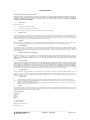
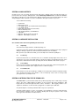
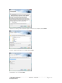
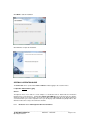
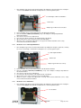
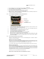
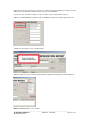
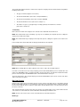
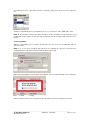
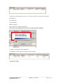
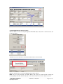
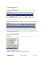
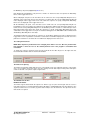
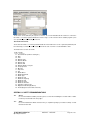
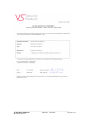
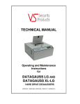
TECHNICAL MANUAL
Operating and Maintenance
Instructions
for
CRUNCH 250
ZZ001220 – ZZ001222
VS SECURITY PRODUCTS LTD
CRUNCH 250
OPERATING MANUAL
PRODUCTION STANDARD
CRUNCH 250 ZZ001220 – 230V 50HZ
CRUNCH 250 ZZ001222 – 115V 60HZ
WARNING
TO AVOID ELECTRIC SHOCK HAZARDS, THE COVER SHOULD ONLY BE REMOVED BY AUTHORISED PERSONNEL
CAUTION
DO NOT ATTEMPT TO CRUNCH ANYTHING THAT IS NOT COVERED BY THE LIST OF ACCEPTABLE MEDIA.
IMPORTANT
THE POWER ON/OFF SWITCH USED ON THIS EQUIPMENT IS NOT AN ISOLATING SWITCH. IT IS RECOMMENDED
THAT THIS EQUIPMENT SHOULD BE OPERATED FROM A SEPARATE SWITCHED ISOLATOR.
COPYRIGHT
This document is the property of VS Security Products Ltd and it may not be reproduced, copied or
exhibited to a third party without the written permission of VS Security Products Ltd.
VS SECURITY PRODUCTS LIMITED
17 Pegasus Court
North Lane
Aldershot
Hampshire GU12 4QP
UK
VS AND ASSOCIATES
3160 Texas Hill Road
Placerville
CA 95667
USA
Tel:
+44 (0) 1252 333577
Fax: +44 (0) 1252 333448
Email: [email protected]
Tel: 530-626-6924
Fax: 530-626-6989
Email: [email protected]
________________________________________________________________________________
VS SECURITY PRODUCTS
Operating Instructions
ZZ001220 - ZZ001222
Page 2 of 30
SOFTWARE LICENCE
VS Security Products Ltd - End-User Licence for Software
PLEASE READ THIS DOCUMENT CAREFULLY BEFORE USING THIS SOFTWARE. THIS LICENCE PROVIDES IMPORTANT INFORMATION CONCERNING THE
SOFTWARE, PROVIDES YOU WITH A LICENCE TO USE THE SOFTWARE AND CONTAINS WARRANTY AND LIABILITY INFORMATION. BY USING THE
SOFTWARE, YOU ARE ACCEPTING THE SOFTWARE "AS IS" AND AGREEING TO BE BOUND BY THE TERMS OF THIS LICENCE AGREEMENT. IF YOU DO NOT
WISH TO DO SO, DO NOT USE THE SOFTWARE.
1.
Terms of Licence
This licence allows you to:
(a)
use the Software on a single computer; and
(b)
make one (1) copy of the Software for back-up purposes.
If you wish to use the Software on more than one computer, you must licence another copy of the Software.
2.
Restrictions on Use
Unless VS Security Products Ltd has authorised you to distribute the Software, you shall not make or distribute copies of the Software or transfer the Software from one
computer to another. You shall not decompile, reverse engineer, disassemble, include in other software, or translate the Software. You shall not modify, alter, change or
otherwise make any modification to the Software or create derivative works based upon the Software. You shall not rent, lease, resell, sub license, assign, distribute or
otherwise transfer the Software or this licence. Any attempt to do so shall be void and of no effect.
3.
Ownership
This licence provides you with limited rights to use the Software. VS Security Products Ltd retains all ownership, right, title and interest in, to and of the Software and all
copies of it. All rights not specifically granted in this licence, including domestic and international copyrights, are reserved by VS Security Products Ltd.
4.
Proprietary Markings
VS Security Products Ltd's logos, product names, manuals, documentation, and other support materials are either patented, copyrighted, trademarked, constitute
valuable trade secrets (whether or not any portion of them may be copyrighted or patented) or are otherwise proprietary to VS Security Products Ltd. You shall not
remove or obscure VS Security Products Ltd's copyright, trade mark or other proprietary notices from any of the materials contained in this package or downloaded
together with the Software.
5.
Disclaimer of Warranties and Technical Support
The Software is provided to you free of charge and on an "as is" basis, without any technical support or warranty of any kind including, without limitation, any warranty or
condition of merchantability, fitness for a particular purpose and non-infringement. SOME JURISDICTIONS DO NOT ALLOW THE EXCLUSION OF IMPLIED
WARRANTIES, SO THE ABOVE EXCLUSION MAY NOT APPLY TO YOU. YOU MAY ALSO HAVE OTHER LEGAL RIGHTS WHICH VARY FROM JURISDICTION TO
JURISDICTION.
6.
Limitation of Liability
VS SECURITY PRODUCTS LTD SHALL NOT BE LIABLE FOR ANY INDIRECT, SPECIAL, INCIDENTAL OR CONSEQUENTIAL DAMAGES OR LOSS, INCLUDING
DAMAGES FOR LOSS OF BUSINESS, LOSS OF PROFITS, OR THE LIKE, WHETHER BASED ON BREACH OF CONTRACT, TORT (INCLUDING NEGLIGENCE),
PRODUCT LIABILITY OR OTHERWISE, EVEN IF VS SECURITY PRODUCTS LTD OR ITS REPRESENTATIVES HAVE BEEN ADVISED OF THE POSSIBILITY OF
SUCH DAMAGES. SOME JURISDICTIONS DO NOT ALLOW THE LIMITATION OR EXCLUSION OF LIABILITY FOR INCIDENTAL OR CONSEQUENTIAL DAMAGES,
SO THIS LIMITATION OR EXCLUSION MAY NOT APPLY TO YOU. The limited warranty, exclusive remedies and limited liability set forth above are fundamental
elements of the basis of the agreement between VS Security Products Ltd and you. You agree that would not be able to provide the limitations.
7.
Term and Termination
This licence agreement is effective until terminated. You may terminate this licence agreement at any other time by destroying all complete and partial copies of the
Software in your possession. This licence and your rights hereunder shall automatically terminate if you fail to comply with any provision of this licence. Upon such
termination, you shall cease all use of the Software and delete the Software and destroy all copies of the Software and other materials related to the Software in your
possession or under your control.
8.
(a)
(b)
(c)
9.
General Provisions
This Agreement shall be governed by and construed in accordance with the laws of England and shall be subject to the jurisdiction of the English Courts.
This Agreement contains the complete agreement between the parties with respect to the subject-matter hereof, and supersedes all prior or contemporaneous
agreements or understandings, whether oral or written.
All questions, comments or concerns with respect to this Agreement shall be directed to: VS Security Products Ltd, 17 Pegasus Court, North Lane, Aldershot,
Hampshire, GU12 4QP, UK (www.veritysystems.co.uk).
Updates
VS Security Products Ltd may from time to time release new versions of the Software. If you wish to be notified when a new version of the Software is released, you must
return the enclosed registration card by email to [email protected]. All new versions or releases which are provided to you shall be considered part of the
Software and shall be governed by the terms of this licence agreement.
VS Security Products Ltd.
17 Pegasus Court
North Lane
Aldershot
Hampshire
GU12 4QP
UK
Tel: +44 (0) 1252 333577
Fax: +44 (0) 1252 333448
Email: [email protected]
www.veritysystems.com
________________________________________________________________________________
VS SECURITY PRODUCTS
Operating Instructions
ZZ001220 - ZZ001222
Page 3 of 30
CONTENTS
SECTION
PAGE
List of Contents
Software Licence
3
1.
Specification
5
2.
Box Contents
6
3.
Hardware Installation
6
4.
Introduction to the CRUNCH 250
6
5.
Software Installation
6-9
6.
Operation Guide
9-11
7.
Data Logger Software
11-17
8.
Interrogating the Database
17-18
9.
Printing Records
19-21
10.
Supervisor Screen
21-25
11.
Safety Recommendations
25
12.
Maintenance
25
13.
EC Declaration of Conformity
29
This document refers to CRUNCH 250
Part No ZZ001220 240/220volts 50Hz
ZZ001222 115volts 60Hz
________________________________________________________________________________
VS SECURITY PRODUCTS
Operating Instructions
ZZ001220 - ZZ001222
Page 4 of 30
SECTION 1: S P E C I F I C A T I O N
With optional SSD Adapter:
SATA, PATA, SCSI, Fiber Channel, Notebook/Laptop Hard Drives (3½” and
2½” all formats and types up to 1.66 height) 2½” Format SSD’s
SSDs
CRUSH TIME
9 seconds (continuous operation)
DESTRUCTION CAPACITY
Per hour: 250 Full Height drives or 500 Laptop Hard Drives typical
POWER SUPPLY
115v 60Hz or 220v-240v 50Hz (Specify when ordering)
POWER CONSUMPTION
4A 115v 60Hz or 2A 220v-240v 50Hz
OPERATING ENVIRONMENT
Temperature: 41ºF – 104ºF (5ºC – 40ºC)
Humidity: 10 to 80% (non-condensing)
MOUNTING
Free standing table top
PACKED DIMENSIONS (W x H x D)
26″ x 19″ x 15″ - (67cm x 50cm x 40cm)
WEIGHT
74lbs (34 kg)
SHIPPING WEIGHT
86lbs (39 kg)
COMPATIBLE
OPERATING SYSTEMS
Windows 8, Windows 7, windows Vista, Windows XP
SP3 or higher (32-bit only)
CONNECTIVITY
Bi Universal serial Bus. 2.0 Full Speed (USB)
MEDIA DESTROYED
ENVIRONMENTAL PROTECTION
Waste electrical products should not be thrown away with household waste.
Please recycle where facilities exist.
Check with your local authority or retailer for recycling advice.
VS Security Products reserves the right to amend or modify the specifications and design criteria
applying to these products
________________________________________________________________________________
VS SECURITY PRODUCTS
Operating Instructions
ZZ001220 - ZZ001222
Page 5 of 30
SECTION 2: BOX CONTENTS
Carefully remove your VS Security Products Crunch 250 from its shipping carton and verify that all parts are
present. If there are missing or damaged parts contact VS Security Products Ltd or an authorized distributor
immediately. If damage has occurred in transit the shipping company must be informed immediately. The carton
and packaging should be retained for use in the event that the unit requires transit for any reason.
You should find the following:
Crunch 250
Mains Power Lead
2 off Adaptor type A (pre-loaded in Destruction Chamber)
2 off Adaptor type B
Debris tray (pre-loaded in the Crunch 250)
Manual / Warranty Card
CD, including Software, and FTDI Drivers.
USB Cable
Optional - Barcode Scanner (if ordered)
Optional - SSD Adaptor (if ordered)
SECTION 3: HARDWARE INSTALLATION
Care should be taken when moving/handling the Crunch 250.
3.1
Unpacking
The Crunch 250 is shipped inside a cardboard packing case.
Unpack the Crunch 250 carefully by disassembling the packing case and inspect it for signs of physical
damage. If damage is apparent, a claim should be filed with the carrier immediately.
Once you have exposed the Crunch 250, you can carefully remove it from the packing box.
3.2
Positioning
Position the Crunch 250 on a hard flat surface at a comfortable working height. Ensure there are no
obstructions to any of the air flow grills which are situated on both the left and right hand sides of the
unit, and also underneath it. Ensure the operating environment is within the limits shown on page 5.
3.2
Power Wiring
Power connection is made to the CRUNCH 250 in the form of a IEC type electrical lead (supplied). The
user should ensure that their power supply meets those outlined on page 5.
3.3
Pre-loaded items
Check that there are two pre-loaded Type A Adaptors in the Destruction Chamber and that the Debris
Tray is situated in the bottom of the chamber. In the event that any of these items is missing contact
your supplier before operating the unit.
SECTION 4: INTRODUCTION TO THE CRUNCH 250
The Crunch 250 is a powerful and fast data destroyer which physically crushes a wide range of storage
devices. The unit is supplied with basic adaptors for most common drive types including 3½” Half
Height, Slim Line and Full Height Hard drives and 2½” hard drives. Data Logging software is also
supplied as standard for use when the unit is plugged into a computer by the USB cable.
An optional adaptor for crunching Solid State Drives may also be purchased.
The Data Logging software is used to record details of the Hard Drives and other media which has
been destroyed. Printable reports are available detailing date destroyed, operator’s name, media
owner, type and serial number of media, and more.
________________________________________________________________________________
VS SECURITY PRODUCTS
Operating Instructions
ZZ001220 - ZZ001222
Page 6 of 30
The Crunch 250 may be operated either with or without the erasure logging function activated. For
information on stand-alone operation proceed to Section 6.1 below.
SECTION 5: SOFTWARE INSTALLATION
The following details the installation procedure for the VSSP Data Logging Software.
5.1 Installing the Data Logging Software
Insert the software installation disc into the CD/DVD drive in your PC, and wait for the VSSP software
installation screen to appear. If the screen does not appear, open ‘My Computer’ and double click on
your CD/DVD drive icon to launch the disc menu. Click on the VSSP_Logger_Auto exe file.
The following screen will then appear regarding FTDI Interface Drivers.
Follow the on screen instructions to install the drivers.
When the FTDI drivers have been installed (If they were not already present)
Click the Install Logger button.
Close all Windows programs that are running and click NEXT
________________________________________________________________________________
VS SECURITY PRODUCTS
Operating Instructions
ZZ001220 - ZZ001222
Page 7 of 30
Tick the box to confirm you have read and accept the software licence conditions and Click NEXT
Check the suggested destination is acceptable and Click NEXT.
Select Number of Users and Click NEXT.
________________________________________________________________________________
VS SECURITY PRODUCTS
Operating Instructions
ZZ001220 - ZZ001222
Page 8 of 30
Click NEXT to start the Installation.
Click FINISH to complete the installation.
SECTION 6: OPERATION GUIDE
The Crunch 250 can be operated either with or without the Data Logging as the customer wishes.
6.1 Operation without Data Logging
General
The Operator must ensure that the correct adaptors as described below are fitted inside the Destruction
Chamber before commencing use. A Hard Drive PCB UP (PC CARD UP) is then introduced into the chamber
and the door firmly closed. Pressing the green “Destroy” button on the right hand side of the display starts the 9
second destruction cycle. At the completion of the cycle the display reads “Media Destroyed Open Door” after
which the media can be safely removed from the machine.
6.1.1
Destruction of 3½” Half Height and Slim Line Hard drives
________________________________________________________________________________
VS SECURITY PRODUCTS
Operating Instructions
ZZ001220 - ZZ001222
Page 9 of 30
1.
Fit 2-off Adaptor Type A into the Destruction Chamber by sliding them along the guide rails ensuring the
T slot is near the bottom. Pull down the locking latches to secure the guides in place.
3½” Half Height or Slim Line Hard Drive
Guide Latch
Adaptor Type A with T Slot near bottom
2.
3.
4.
5.
6.
7.
6.1.2
1.
Ensure the Debris Tray is inserted in the bottom of the Destruction Chamber
Place the Hard Drive PCB UP (PC Card UP) on top of the Adaptors locating it fully within the
Destruction Chamber
Close the door and ensure it is fully latched
Press the green “Destroy” button on the right hand side of the display
Observe the progress of the destruction cycle in the LCD display
When the cycle is complete the “Open Door” message shows and the Hard Drive can be safely
removed from the Destruction Chamber
Destruction of 3½” Full Height Hard drives
Fit 2-off Adaptor Type A into the Destruction Chamber by sliding them along the guide rails, ensuring
the T slot is near the top. Pull down the locking latches to secure the guides in place.
3½” Full Height Hard Drive
Guide Latch
Adaptor Type A with T slot near top
2.
3.
4.
5.
6.
7.
6.1.3
1.
Ensure the Debris Tray is inserted in the bottom of the Destruction Chamber
Place the Hard Drive PCB UP (PC CARD UP) on top of the Adaptors locating it fully within the
Destruction Chamber
Close the door and ensure it is fully latched
Press the green “Destroy” button on the right hand side of the display
Observe the progress of the destruction cycle in the LCD display
When the cycle is complete the “Open Door” message shows and the Hard Drive can be safely
removed from the Destruction Chamber
Destruction of 2½’’ Hard Drives
Fit 2-off Adaptor Type B into the Destruction Chamber by sliding them along the guide rails ensuring the
T slot is near the bottom. Pull down the locking latches to secure the guides in place.
2½” Hard Drive
________________________________________________________________________________
VS SECURITY PRODUCTS
Operating Instructions
ZZ001220 - ZZ001222
Page 10 of 30
Adaptor Type B with T Slot near
bottom
2.
3.
4.
5.
6.
7.
6.1.4
Guide Latch
Ensure the Debris Tray is inserted in the bottom of the Destruction Chamber
Place the Hard Drive on top of the Adaptors locating it fully within the Destruction Chamber
Close the door and ensure it is fully latched
Press the green “Destroy” button on the right hand side of the display
Observe the progress of the destruction cycle in the LCD display
When the cycle is complete the “Open Door” message shows and the Hard Drive (Or SSD) can be
safely removed from the Destruction Chamber
Use of the Optional SSD Adaptor to destroy Solid State Drives
An SSD Adaptor is available as an optional purchase.
SSD Adaptor
Solid State Drive
Guide Rail
Media Extraction Handle
1.
2.
3.
4.
5.
6.
7.
8.
6.1.5
Hold the SSD adaptor with the media extraction handle towards the operator and insert in to the
Destruction Chamber by sliding it along the guide rail.
Ensure that the SSD Adaptor snaps firmly into position in the centre of the Chamber and moves
neither forward or back
Check that the Debris Tray is situated at the bottom of the chamber
Insert the Solid State Drive completely into the Adaptor
Close the door and ensure it is fully latched
Press the green “Destroy” button on the right hand side of the display
Observe the progress of the destruction cycle in the LCD display
When the cycle is complete the “Open Door” message shows and the media can be safely
removed from the Destruction Chamber by gently pulling the media extraction handle to bring the
Drive out of the Adaptor
Error messages and the Stop / Reverse Button
The Stop / Reverse button is located on the left of the LCD display panel. Instructions and Error
Messages are shown in the display.
Message: “Incorrect insert or media type”
After insertion of the media to be destroyed into the Destruction Chamber and the latched closure of the
safety door, the message “incorrect insert or media type” will be shown if the item inserted does not
fit expected parameters of size or position, and the Destruction Cycle will not start.
To correct this, open the safety door and check the media type and position and correct as necessary.
Message: “user pressed stop”
In the event that the Operator wishes to stop the machine mid-cycle the Stop / Reverse button can be
pressed. The message “user pressed stop” will be shown in the LCD. In order to reverse the Crunch
250 to the Start position the Stop / Reverse button must be pressed for more than 3 seconds and held
down until the unit has returned to start. This ensures the crushing mechanism has been removed from
the Media which in turn can now be removed from the Destruction Chamber.
The Destroy cycle can only be initiated from the Start position.
Message: “Error – Motor Stalled” and “Press and hold Reverse to Reset”
________________________________________________________________________________
VS SECURITY PRODUCTS
Operating Instructions
ZZ001220 - ZZ001222
Page 11 of 30
In the event of a cycle failure due to a stalled motor (jam/stall) or overheating of the motor (such as may
occur if the item in the Destruction Chamber is not suitable to be crushed) the error message “Error –
Motor Stalled” is shown, followed by the message “Press and hold Reverse to Reset”
To correct this, the Stop / Reverse button must be pressed for more than 3 seconds and held down until
the unit has returned to start. If the Crunch 250 has overheated it will be necessary to wait until the
motor has cooled sufficiently before the reset is effective.
Message: “motor stalled switch off”
If this message is shown in the LCD the Crunch 250 must be switched off.
The Crunch 250 should then be restarted and the operator should carry out any instructions that are
shown in the LCD. If the message above is repeated and the unit does not reboot correctly switch the
machine off and contact technical support.
6.2 Operation with Data Logging
General
To operate the Crunch 250 with logging software it must first be connected to a PC or Laptop with the program
already loaded (see Section 5: Software Installation). Information is entered onto the software via keyboard or
optional barcode scanner to speed up the data entry if required. Once the software has located the Crunch 250
it will remain connected while different Adaptors are fitted, if required, to complete a job where a variety of types
of media are to be destroyed.
6.2.1
Destruction of 3½” Full Height Hard drives
1.
2.
Prepare the Destruction Chamber as described in 6.1.1 Points 1 and 2 above
Open the Data Logging program and click the “Find Machine” button and the Crunch 250 display
will show it is in remote mode controlled by the computer
Enter data into the software as required
Place the Hard Drive PCB UP (PC CARD UP) on top of the Adaptors locating it fully within the
Destruction Chamber
Close the door and ensure it is fully latched
Start the destruction cycle by clicking the “Destroy” button on the computer screen
Observe the progress of the destruction cycle in the LCD display
When the cycle is complete the “Open Door” message shows and the media can be safely
removed from the Destruction Chamber
Repeat the process from 3. above for destruction of similar media
3.
4.
5.
6.
7.
8.
9.
6.2.2
Destruction of 3½” Half Height and Slim Line Hard
1.
2.
9.
Prepare the Destruction Chamber as described in 6.1.2 Points 1 and 2 above
Open the Data Logging program and click the “Find Machine” button and the Crunch 250
display will show it is in remote mode controlled by the computer
Enter additional data into the software as required
Place the Hard Drive PCB UP (PC CARD UP) on top of the Adaptors locating it fully within the
Destruction Chamber
Close the door and ensure it is fully latched
Start the destruction cycle by clicking the “Destroy” button on the screen
Observe the progress of the destruction cycle in the LCD display
When the cycle is complete the “Open Door” message shows and the media can be safely
removed from the Destruction Chamber
Repeat the process from 3. above for destruction of similar media
6.2.3
Destruction of 2½” Hard Drives
3.
4.
5.
6.
7.
8.
1.
2.
3.
4.
5.
6.
7.
8.
Prepare the Destruction Chamber as described in 6.1.3 Points 1 and 2 above
Open the Data Logging Program and click the “Find Machine” button and the Crunch 250 display
will show it is in remote mode controlled by the computer
Enter additional data into the software as required
Place the media on top of the Adaptors locating it fully within the Destruction Chamber
Close the door and ensure it is fully latched
Start the destruction cycle by clicking the “Destroy” button on the screen
Observe the progress of the destruction cycle in the LCD display
When the cycle is complete the “Open Door” message shows and the media can be safely
removed from the Destruction Chamber
________________________________________________________________________________
VS SECURITY PRODUCTS
Operating Instructions
ZZ001220 - ZZ001222
Page 12 of 30
9.
6.2.4.
Repeat the process from 3. above for destruction of similar media
Use of the Optional SSD Adaptor to destroy Solid State Drives
1.
2.
3.
4.
5.
6.
7.
8.
9.
Prepare the Destruction Chamber as described in 6.1.4 Points 1 and 2 above
Open the Data Logging Program and click the “Find Machine” button and the Crunch 250 display
will show it is in remote mode controlled by the computer
Enter additional data into the software as required
Insert the Solid State Drive completely in to the Adaptor
Close the door and ensure it is fully latched
Start the destruction cycle by clicking the “Destroy” button on the screen
Observe the progress of the destruction cycle in the LCD display
When the cycle is complete the “Open Door” message shows and the media can be safely
removed from the Destruction Chamber
Repeat the process from 3. above for destruction of similar media.
Details of how to operate the Data Logging software are given in Section 7 below
To revert to using the Crunch 250 without the Data Logging Software, disconnect the USB Cable, close it down
and reboot it.
SECTION 7: HOW TO USE THE DATA LOGGING SOFTWARE
Overview
The VSSP Data Logger is a Microsoft © Windows application program that allows users to automatically log
the erasing or destruction of media by VSSP Degaussers and Crusher machines. It is connected to the
Degausser or Crusher via a USB Cable. Degaussing or Crushing can be started from the program by clicking
the 'Destroy' button.
When the Degaussing or Crushing is complete, the program collects destruction data from the machine and logs
the data in a database.
Information about the processing company, the media owner and the media can be entered in the data boxes on
the main screen. This information is stored in the database together with the media destruction information when
the media destruction is completed.
It is possible to interrogate the database to retrieve the destruction information record. This record or a number
of records can be printed out using a printer attached to the computer including network printers.
7.1 Logger Operation
Starting the Logger
________________________________________________________________________________
VS SECURITY PRODUCTS
Operating Instructions
ZZ001220 - ZZ001222
Page 13 of 30
To start the logger double click on the program icon or select the program from the programs list and click on the
program title.
The first time the program is started the Media Processed box will be empty. This is because the database
contains no records.
Also the Degausser/Crusher machine details will be blank. This is because the logger is not connected to a
machine yet.
7.2 Connecting to a Machine
1) Plug one end of the USB lead into the VSSP Degausser / Crusher machine.
2) Plug the other end of the USB lead into a USB port on the computer that the VSSP Logger program is running
on.
3) Turn the Degausser / Crusher machine on.
NOTE: If this is the first time this machine has been connected to this computer, there may be a delay as the
USB drivers are installed. There may also be various dialog boxes displayed to the user whilst the USB driver
________________________________________________________________________________
VS SECURITY PRODUCTS
Operating Instructions
ZZ001220 - ZZ001222
Page 14 of 30
install is being carried out and the user may have to confirm that the driver installation should proceed. The
USB interface is an FTDI device and there may be references to the FTDI driver.
If you are not clear on the driver install process, get a member of your IT support team to help you.
4) When the FTDI USB driver has installed, click the 'Find Machine' button on the VSSP Logger main screen.
This will cause the logger to look for a VSSP machine:
When the machine has been located, the machine details are displayed in the Degausser/Crusher details box.
NOTE: The 'DESTROY' button is now enabled.
________________________________________________________________________________
VS SECURITY PRODUCTS
Operating Instructions
ZZ001220 - ZZ001222
Page 15 of 30
The current date and time which are read from the computer are displayed in the machine details along with the
following machine data:
•
The type of machine (Degausser or Crusher)
•
The machine Model Name (in the above example 'DataGauss')
•
The machine Serial Number (in the above example 14060428)
•
The machine firmware version (in the above example 1.7)
•
The number of 'cycles' (e.g. degaussing or crushing operation) the machine has executed
(in the above example 10)
7.3 Data Entry
Before an item of media can be degaussed or crushed, various data fields must be filled out.
NOTE: Not all data fields may be mandatory (e.g. they can be left blank), this depends upon the settings the
supervisor has made for the logger.
NOTE: Not all data fields may be displayed. This depends upon the settings the supervisor has made for the
logger.
In the example below, all the data fields are displayed and all have text completed:
NOTE: When entering data, the 'Tab' key will cause the cursor to skip to the next data entry box.
In normal use the data in the 'Processing Company' panel and the 'Media Owner' panel is retained after each
instance the 'DESTROY' button is clicked and media is destroyed. However, the data in the 'Media Information'
panel is cleared every time the 'DESTROY' button is clicked and media is destroyed.
The 'Clear' button in the 'Processing Company' panel and the 'Media Owner' panel can be used to clear all the
entries in the panel if required.
Bar Code Scanner
If the bar code scanner has been installed, it can be used to enter bar code data such as serial numbers directly
into the relevant data entry box. So, if you wanted to read a bar code serial number into the 'Serial No' data entry
box, first ensure that the cursor is in the box (either click in the box with the mouse or use the 'Tab' key to move
the cursor to the box).
Then point the Bar Code Scanner at the bar code and press the 'Read Trigger' on the scanner. When the bar
code scanner has scanned the bar code the data will be automatically inserted in the box.
NOTE: The bar code scanner can be used to enter data into any of the data entry boxes.
Media Type
________________________________________________________________________________
VS SECURITY PRODUCTS
Operating Instructions
ZZ001220 - ZZ001222
Page 16 of 30
The 'Media Type' box has a drop down list which is revealed by clicking on the down arrow on the right of the
box.
Select the required 'Media Type' by clicking with the mouse on one of the three entries (HDD, SSD or Tape).
NOTE: All the information entered in the data boxes will be stored in the database media destruction record
together with machine details, the time and date of destruction and the destruction data returned from the
machine.
7.4 Destroying Media
When the required data has been entered in the data boxes, the user can click on the 'DESTROY' button to
destroy the media.
NOTE: If one or more of the 'mandatory' data entry boxes (as defined by the supervisor) is blank, then the
following warning message will be displayed and the destruction will not start.
When all the relevant data boxes have entries, destruction will commence and the following screen is displayed:
When the destruction process has completed, the destruction data is shown in the 'Media Processed' box:
________________________________________________________________________________
VS SECURITY PRODUCTS
Operating Instructions
ZZ001220 - ZZ001222
Page 17 of 30
The data shown in the 'Media Processed' box is a 'snapshot' of the data record and shows the key data:
Record Number
Date of Destruction
Time of Destruction
Media Serial Number
Result – Degaussed / Crushed (as applicable)
If there was an error during destruction then the error dialog box will be displayed:
To clear the error dialog box, click the 'OK' button.
The 'Media Processed' box will now show that the destruction failed:
7.5 Closing the Logger
________________________________________________________________________________
VS SECURITY PRODUCTS
Operating Instructions
ZZ001220 - ZZ001222
Page 18 of 30
SECTION 8: INTERROGATING THE DATABASE
8.1 Selecting Records
To select a record to be viewed, click on the record to be viewed in the 'Media Processed' List.
The record will then be highlighted and the record data shown in the data entry fields above.
NOTE: The 'DESTROY' button is now disabled.
The above can be repeated for each record that is to be viewed.
________________________________________________________________________________
VS SECURITY PRODUCTS
Operating Instructions
ZZ001220 - ZZ001222
Page 19 of 30
8.2 Resuming Destruction after Interrogation
When the database records are being interrogated the 'DESTROY' button is disabled. To enable the button, click
the 'Resume' button.
This will then cause the machine to check that the VSSP machine is still connected:
When the VSSP machine is located, the 'DESTROY' button will be enabled.
NOTE: Any 'Processing Company' and 'Media Owner' data entry boxes that had data entered prior
to interrogating the database will have that data re-entered into them when the 'Resume' button is pressed.
________________________________________________________________________________
VS SECURITY PRODUCTS
Operating Instructions
ZZ001220 - ZZ001222
Page 20 of 30
SECTION 9: PRINTING RECORDS
9.1 Selecting a Record to Print
To select a record to be printed, click on the record to be printed in the 'Media Processed' List.
The record to be printed will then be highlighted. Now click the 'Print' button, the normal print dialog box will be
displayed. Select the printer to which the record is to be sent, set the number of copies required and click OK.
The Record Data is now sent to the printer.
Page 1 – 20/06/2014 – 14:31:28
Media Destruction Record
Company
Name:
Operator:
Supervisor:
Degaussing on Site:
VSSP
Victoria
Brian
Yes
Media Owner
Company Name:
Department:
ICL Engineering
Engineering
Media Information
Type:
Serial Number:
Capacity:
Part Number:
Security Classification:
Remarks:
HDD
79429-499
Unknown
IBM 4430-946
None
Search Failures
Degausser/Crusher Details
Date:
Time:
Degausser/Crusher
Model:
Serial Number:
Firmware Version:
Number of Cycles:
20/06/2014
12:31:09
Crusher
Crunch 250
14060428
1.7
22
Destruction Details:
Result:
Degaussed / Crushed (as appropriate)
-----------------------------------------------------------------------------------------------------------------------------------The date and time of the printing is stated at the top of the record page.
NOTE: The line spacing of print used can be set by the supervisor.
________________________________________________________________________________
VS SECURITY PRODUCTS
Operating Instructions
ZZ001220 - ZZ001222
Page 21 of 30
9.2 Selecting Multiple Print Records
The printing of multiple records can be achieved by left clicking the mouse on the first record required, holding
the left click button down and dragging the mouse down to the last record to be printed. This will highlight all the
records between the first and last selected.
Alternatively, highlight the first record to be printed, hold the shift key down and select the last record to be
printed. This will cause all records in between to be printed.
If you require printing multiple records that are not sequential, click the first record to be printed, hold the Control
(Ctrl) key down and click the individual records to be printed.
When you have selected the records to be printed, click the 'Print' button, the normal print dialog box will be
displayed. Select the printer to which the record is to be sent, set the number of copies required and click OK.
The Record Data is now sent to the printer.
NOTE: Each record is printed on a separate page.
9.3 Resuming Destruction after Printing
When the database records are being printed the 'DESTROY' button is disabled. To enable the button, click the
'Resume' button.
This will then cause the machine to check that the VSSP machine is still connected:
________________________________________________________________________________
VS SECURITY PRODUCTS
Operating Instructions
ZZ001220 - ZZ001222
Page 22 of 30
When the VSSP machine is located, the 'DESTROY' button will be enabled.
NOTE: Any 'Processing Company' and 'Media Owner' data entry boxes that had data entered prior to printing will
have that data re-entered into them when the 'Resume' button is pressed.
SECTION 10: SUPERVISOR SCREEN
10.1 Supervisor Password
To show the 'Supervisor' screen, click on the 'File' menu and select 'Supervisor'.
This 'Password' screen will then be displayed.
To enter the 'Supervisor' screen, the correct password must be entered.
________________________________________________________________________________
VS SECURITY PRODUCTS
Operating Instructions
ZZ001220 - ZZ001222
Page 23 of 30
The default password is: password
Note this is all lower case.
The password can be changed in the supervisor screen.
NOTE: If supervisor password has been changed, please make a note of it. Once changed it cannot be
reset to the default password even if the program is un-installed and re-installed.
If the correct password is entered, the supervisor screen will be displayed.
________________________________________________________________________________
VS SECURITY PRODUCTS
Operating Instructions
ZZ001220 - ZZ001222
Page 24 of 30
10.2 Supervisor Screen
The supervisor screen has sections for each of the data entry panels:
The 'Data Entry' panels (highlighted by Red boxes) are as follows:
•
Degaussing Company Records
•
Media Owner Records
•
Media Information Records
Each 'Data Entry Panel' has two sub panels:
the 'Displayed' sub panel (highlighted by Green boxes)
________________________________________________________________________________
VS SECURITY PRODUCTS
Operating Instructions
ZZ001220 - ZZ001222
Page 25 of 30
the 'Mandatory' sub panel (highlighted by Blue boxes).
Each 'Displayed' and 'Mandatory' sub panel has a number of 'Tick Boxes' that correspond to the Data Entry
Boxes on the Logger main screen.
On the 'Displayed' sub panel, a tick box with a tick in it will cause the corresponding Data Entry Box to be
displayed on the Logger main Screen. If the Tick Box is not ticked, then the corresponding Data Entry Box will
not be displayed on the Logger main Screen. This allows the supervisor to specify exactly which Data Entry
Boxes are to be displayed on the Logger main screen.
On the 'Mandatory' sub panel, a tick box with a tick in it will cause the corresponding Data Entry Box to
be 'Mandatory' e.g. it must contain some data prior to the ‘Destruction’ button being clicked. If the Tick Box is not
ticked, then the corresponding Data Entry Box is not 'Mandatory' and does not have to contain data prior to the
Destruction button being clicked. This allows the supervisor to specify exactly which Data Entry Boxes must
contain data on the Logger main screen prior to destruction taking place. The 'DESTROY' button is inhibited until
all 'Mandatory' Data Entry Boxes have data.
The 'Equipment Records' panel allows the supervisor to specify which equipment records are displayed on the
Logger main screen. If a particular record tick box is ticked, the record will be displayed on the main screen. If a
particular record tick box is not ticked, the record will not be displayed on the main screen.
10.3 Setting the Password
NOTE: When supervisor password has been changed, please make a note of it. Once the password has
been changed it cannot be reset to the default password even if the program is un-installed and
re-installed.
To change the supervisor password, enter the new password into the data entry box to the right of the 'Set
Password' button and then click the 'Set Password' button.
10.4 Printer Line Spacing
The 'Printer Line Spacing' setting allows the lines on the printed records to be adjusted. If the lines on the printer
are too close together, increase the value of the line spacing set in the data entry box. Most printers will require
a value of about 70; some printers require a higher value.
10.5 Database File Archive
Database File Archive
The 'Archive Log File' button allows the supervisor to 'Archive' (e.g. store) the current log file, this also causes a
new empty log file to be created. Clicking the button will display a standard Windows Save File dialog box. The
supervisor can then choose a location (e.g. drive and/or folder) to store the archive file. The supervisor can also
name the file as required.
________________________________________________________________________________
VS SECURITY PRODUCTS
Operating Instructions
ZZ001220 - ZZ001222
Page 26 of 30
The file name can be defined by the supervisor, however, it is recommended that the file extension is .csv as the
file format is a comma separated variable file and choosing a .csv file extension allows suitable programs (such
as a spreadsheet) to automatically open the file.
10.6 Archive File Format
The archive file format is a comma separated variable file. Each field in the record is separated (de-limited) from
the next field by a comma. The fields contain alpha numeric text. A comma is not allowed within a field.
The fields in the record are as follows:
Field Contents
===== ========
01 - Record Number (Numeric starting at 1)
02 - Date
03 - Time
04 - Machine Type
05 - Machine Model
06 - Machine SN
07 - Machine FW
08 - Machine Number of Cycles
09 - Company Name
10 - Operator
11 - Supervisor
12 - Site
13 - Media Owner
14 - Media Department
15 - Media Type
16 - Media Info SN
17 - Media Info Capacity
18 - Media Info PN
19 - Media Info Class
20 - Media Info Remarks
21 - Capacitor Voltage (Volts)
22 - Magnetic Field Strength (Gauss)
23 - Result (Degaussed, Crushed, Failed etc.)
SECTION 11: SAFETY RECOMMENDATIONS
11.1
Gloves
It is recommended that suitable protective gloves are worn when handling the crushed media or debris
in order to protect hands from sharp edges.
11.2
Swarf
It recommended that the Debris Collection Tray is emptied frequently to prevent the build up of swarf
inside the Crunch 250.
________________________________________________________________________________
VS SECURITY PRODUCTS
Operating Instructions
ZZ001220 - ZZ001222
Page 27 of 30
SECTION 12: MAINTENANCE
12.1
Resetting the circuit breaker
The Crunch 250 Degasser is not equipped with any on-board fuses that require replacement. All the
systems within the unit are protected by the circuit breaker which is located on the rear of the unit – this
can be manually reset by the user.
If the unit fails in any way, the user should verify the condition of the circuit breaker prior to contacting
support.
The Crunch 250 Degausser contains mains voltages and currents. For safety reasons, VS Security
Products Ltd does not recommend that the covers be removed by anyone other than trained VS Security
Products technicians.
12.2
Cleaning
Excess dust or debris should be regularly cleaned from the Destruction Chamber and Guide Rails using
either a cloth and/or by vacuuming. The outside of the unit may be wiped with a soft cloth but no harsh
cleaning agents should be used.
________________________________________________________________________________
VS SECURITY PRODUCTS
Operating Instructions
ZZ001220 - ZZ001222
Page 28 of 30
________________________________________________________________________________
VS SECURITY PRODUCTS
Operating Instructions
ZZ001220 - ZZ001222
Page 29 of 30
VS SECURITY PRODUCTS LIMITED
17 Pegasus Court
North Lane
Aldershot
Hampshire GU12 4QP
UK
VS AND ASSOCIATES
3160 Texas Hill Road
Placerville
CA 95667
USA
Tel:
+44 (0) 1252 333577
Fax: +44 (0) 1252 333448
Email: [email protected]
Tel: 530-626-6924
Fax: 530-626-6989
Email: [email protected]
________________________________________________________________________________
VS SECURITY PRODUCTS
Operating Instructions
ZZ001220 - ZZ001222
Page 30 of 30