1
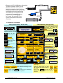
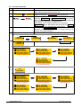
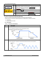
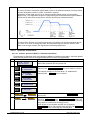
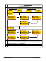
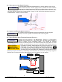
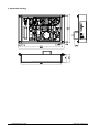
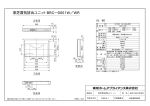
CTC-33 Effortless Controller
Instruction Manual
Document No.
Ver. 1.21
DyadicSystems Co.,Ltd.
DEE-00274C-EN
2003 / 04 / 17
DEE-00247C-EN-1/23
Table of Contents
1. FEATURES OF CTC-33 EFFORTLESS CONTROLLER ....................................................................................3
1.1. SUMMARY OF OPERATION .................................................................................................................................3
1.2. THE PROCEDURE OF A SEQUENCE STEP EXECUTION IN THE CTC-33 ...................................................................4
1.3. THE SIGNALS DEFINEITION AND PIN ASSIGNMENT OF EXTERNAL I/O CONNECTOR .................................................4
1.4. THE CONNECTION BETWEEN THE CTC-33 AND THE ACTUATORS .........................................................................5
2. THE OPERATION OF SEQUENCE TEACH........................................................................................................6
2.1. TO SPECIFY THE AXES TO BE EXECUTED POSITIONING ........................................................................................6
2.2. TO SPECIFY WAITING THE COMPLETION OF THE POSITIONING ..............................................................................6
2.3. THE CONDITION OF INPUT SIGNALS FOR THE SEQUENCE PROGRESSION ...............................................................6
2.4. TO INPUT THE TIME FOR WAITING .......................................................................................................................6
2.5. TO INPUT THE DATA INTO OUTPUT SIGNALS ........................................................................................................6
2.6. CONT. STEP AND END STEP ............................................................................................................................7
3. THE EXRTENDED FUNCTION OF THE SEQUENCE CONTROL .....................................................................7
3.1. TO SELECT THE MONITORING ITEM WHEN THE SEQUENCE IS EXECUTING ..............................................................7
3.2. THE EXTENDED FUNCTION ABOUT THE ACTUATOR ..............................................................................................8
3.2.1. Offset for Home Position......................................................................................................................8
3.2.2. Offset for Displayed Position...............................................................................................................9
3.2.2. Individually setteable ZONE signal output range for each Position................................................9
4. DETAIL OF POSITIONING PROGRAMMING OPERATIONS ..........................................................................10
4.1. STANDARD POSITIONING PROGRAMMING OPERATIONS ....................................................................................10
4.1.1. Common Operation.............................................................................................................................11
4.1.2. Position Teach-Jog .............................................................................................................................12
4.1.3. Position Data Input .............................................................................................................................12
4.1.4. Speed Data Input.................................................................................................................................12
4.1.5. PUSH DATA INPUT (VALID ONLY WHEN PUSH POSITIONING MODE IS SELECTED) .............................................12
4.1.6. Acceleration Data Input ......................................................................................................................13
4.2. ADVANCE POSITIONING PROGRAMMING OPERATIONS ......................................................................................13
4.2.1. Detail Mode ..........................................................................................................................................13
4.3. ACTUATOR PARAMETER MODE .......................................................................................................................17
4.3.1. Home Direction Set ( Basic Function )..............................................................................................18
4.3.2. Stroke Limit End Set ( Basic Function )............................................................................................18
4.3.3. Home Position Offset Teaching ( Extended Function )...................................................................18
4.3.4. Home Position Offset Input ( Extended Function )..........................................................................19
4.3.5. Offset for Displayed Position ( Extended Function ).......................................................................19
4.3.6. Individually setteable ZONE signal output range for each Position..............................................20
5. TO CHANGE THE AXIS NUMBER OF THE ACTUATOR.................................................................................21
6. DEMENTION DRAWING....................................................................................................................................22
DyadicSystems Co.,Ltd.
DEE-00247C-EN-2/23
1. Features of CTC-33 Effortless Controller
The basic operation of the CTC-33
Effortless Controller is very easy. It
allows the operators to enter and edit
both position data and its sequence by
just following the panel instructions.
This makes you to escape from the
confusion of a complicated ladder
programming and debugging.
As a result, the lead-time of your
system development will shorten
drastically.
RUN
TEACH
RUN
AXIS NUMBER OF
THE ACTUATOR
FOR TEACH
SERVO ON
AXIS
SELECT
HOMED
POSITION
RUN
JOG/HANDLE
FWD
POSITION TEACH
SEQUENCE TEACH
HOMING
FINAL STEP
NEXT
STEP
POSITION
SELECT
POSITION
TO
EXECUTE
POSITION
SELECT
POS. JOG/TEACH
POS. EXEC WAITING
IN COND. TO PROGRESS
PUSH FORCE DATA IN
ACCEL/DECEL DATA IN
RVS
PUSH
POISTIONING
AXES TO EXECUTE
POS. DATA INPUT
SPEED DATA INPUT
FINE
ADJUST
DELAY TIMER
DATA TO OUTPUT
DATA
ENTRY
MODE
DATA
ENTRY
MODE
END
STEP
NORMAL
POISTIONING
CONT.
STEP
DESTINATION POS.
START POS.
WRITE
WRITE
CTC-33
1.1. Summary of operation
Teach position data ( the left side )
Edit sequence ( the right side )
POSITION TEACH
E Position Teach
00001.000 mm
SEQUENCE TEACH
First time after powering ON,
POSITION TEACH is selected
RUN
TEACH
RUN
To run the sequence, press
RUN/TEACH key or Make turn
ON the SQSTR input.
RUN
●RUN is turning ON,
TEACH
if sequence is running
POSITION TEACH
AXIS Select the axis
SELECT number to teach.
HOMING
Press until
●HOMED
has turned ON.
AXIS NUMBER OF
THE ACTUATOR
FOR TEACH
SERVO ON
POSITION Select the position
SELECT to be taught.
HOMED
POSITION
RUN
DATA
Select the item to
ENTRY
MODE teach.
●JOG/HANDLE
To
teach the actual position
by moving the actuator.
JOG/HANDLE
FWD
E Position teach
00001.000 mm
●POS. DATAINPUT To input the
position into the memory
E Position edit
00001.000 mm
●SPEEDDATAINPUT To input
the speed into the memory.
E Speed Input
0100.0 mm/sec
AXIS
SELECT
PUSH
POISTIONING
HOMING
FINAL STEP
NEXT
STEP
POSITION
SELECT
POSITION
TO
EXECUTE
POSITION
SELECT
POS. JOG/TEACH
AXES TO EXECUTE
POS. DATA INPUT
POS. EXEC WAITING
SPEED DATA INPUT
IN COND. TO PROGRESS
PUSH FORCE DATA IN
DELAY TIMER
ACCEL/DECELDATAIN
DATA TO OUTPUT
WRITE
NORMAL
POSITIONING
WRITE
Use ←→
to move
cursor
CONT.
STEP
WRITE
S00 Axes to move
#0 #1 #2 # #
●IN. CONDTOPROGRESS To input
the condition of input signals for
the sequence progression.
■ON
S00 In condition
□OFF
X Don’t 0■
■ 1□
□ 2X 3X 4X
care
●DELAYTIMER To input the
time for waiting in this step.
S00 Delay timer
001.00 sec
Please decide which mode is to be
used, Normal Positioning or Push
Positioning.
Please press WRITE key after the set of Positioning
data to save into Mechatronics Cylinder.
DyadicSystems Co.,Ltd.
END
STEP
DESTINATION POS.
●PUSH FORCE DATA IN To input the Push Force data for
Push Positioning, if you select the Push Positioning mode.
PUSH
POSITIONING
Select SEQUENCE TEACH mode
Select the sequence step
NEXT
to edit.
STEP
S00 Axes to move
#0 #1 #2 # #
POSITION
Select the point to be SELECT
executed in this step.
DATA
ENTRY
MODE
●AXES TOEXECUTE
To input
the axis identifiers of axes to
be executed positioning.
DATA
ENTRY
MODE
DATA
ENTRY
MODE
NORMAL
POISTIONING
START POS.
SEQUENCE TEACH
Select the item to edit.
FINE
ADJUST
RVS
POSITION TEACH
SEQUENCE TEACH
●DATATO OUTPUT
in this step.
To input the data into Output signals
If the step should be the end of
sequence, please select the End
Step. In other case, please select the
Cont. Step
END
終了
STEP
ステップ
Please press WRITE key after the set of
Sequence data to save into CTC-33 Effortless
Controller
CONT.
継続
STEP
ステップ
WRITE
DEE-00247C-EN-3/23
1.2. The procedure of a sequence step execution in the CTC-33
The each of sequence steps in the CTC-33 is executed as shown below.
Start of sequence
Is start requested?
After the CTC-33 is powering ON, the sequence is
started to run when the RUN/TEACH key is pressed or
the SQSTR input is turned ON.
is turning ON, if sequence is running.
●RUN
NO
The axes specified to move at the ●AXES TOEXECUTE
entry are instructed to move for specified position.
If you enter the space ( the default value ) in all axes
entry, no instruction to move is instructed.
YES
The specified axes of actuator
are instructed to move the
position
If the value TRUE ( the default value ) is specified at the
●POS. EXEC. WAITING entry, the CTC-33 will wait the
completion of the positioning. If the value FALSE is
specified, no completion of positioning is waited.
And then, CTC-33 confirms the condition of the IN0 to
●IN.
CONDTOPROGRESS
IN5
inputs
specified
at
the
entry.
If the value X ( the default value = don’t care ) in all of
NO
Is positioning
completed?
YES
NO
Is the input
condition sure?
The CTC-33 inserts the pause of the time specified in
●DELAY TIMER
YES
The CTC-33 sets output OUT0 to OUT5 to the values
specified at the ●DATA TO OUTPUT entry.
If the value X ( the default value = no change ) in the
entry OUT0 to OUT5, the state of that output will be
maintained in the previous state.
The pause of specified delay
time is inserted.
The output signals are set to
the specified data.
NO
Is the step END
step?
YES
END
終了
STEP
ステップ
If the step is END step and the SQSTR input is OFF, the
execution of the sequence will be stopped. If the step is
END step and the SQSTR input is ON, the execution of
the sequence will be restarted from the start step.
CONT.
継続
STEP
ステップ
If the step is CONT. step, the next step will be executed
continuously.
End of sequence
1.3. The signals definition and pin assignment of external I/O connector
Input Signals
Pin Name
Description
Pin
20 IN0
Condition Input0
8
19 IN1
Condition Input1
7
18 IN2
Condition Input2
6
17 IN3
Condition Input3
5
16 IN4
Condition Input4
4
15 IN5
Condition Input5
3
14 SQSTR Start Sequnce Step
2
13 SQSTP Forced Stop Sequnce
1
11,12 ICOM Input Common (connect to +24V9,10
Name
OUT0
OUT1
OU12
OUT3
OUT4
OUT5
SQFIN
*ALM
OCOM
Output Signals
Description
Genegral purpose output0
Genegral purpose output1
Genegral purpose output2
Genegral purpose output3
Genegral purpose output4
Genegral purpose output5
End of Sequence Cycle
Alarm State Indicator
Output common (connect to 0V)
Signals of external I/O connector (Maker: Hirose Type: HIF38A-20PA2.54DS)
ICOM (Input Common)
3.9kΩ
Ω
8.2kΩ
Ω
DyadicSystems Co.,Ltd.
Equivalent circuit
of each input
IN0 to IN5
OUT0 to OUT5
Equivalent circuit
of each output
OCOM(Output Common)
DEE-00247C-EN-4/23
RUN
TEACH key or turned ON the Sequence Start ( SQSTR )
To execute the sequence, please press
Input. The sequence is started from Step No.00, and then step-by-step execution to next steps is
continued until the END step is encountered. If the step to execute is reached to the FINAL step
(usually Step No.41) until END Step is encountered, the FINAL step is treated as the END step. If the
execution of the END step is complete, the Sequence Complete ( SQFIN ) output is turned ON and if
the SQSTR input is OFF at that time, the execution of the sequence will be stopped. If the SQSTR input
is ON at that time, the execution of the sequence will be restarted from the start step. This means that
the sequence cycle is automatically repeatable. If you turned ON the Sequence Stop ( SQSTP ) input,
the execution of all of the actuators’ positioning and the sequence will be stop immediately. Because
the priority of the SQSTP input is higher than it of the SQSTR Input, the SQSTP input force to stop the
sequence execution even if the SQSTR Input is maintained ON for cyclic execution.
The Alarm ( *ALM ) output is ON when the CTC-33 is normal. The *ALM is OFF when the CTC-33 or
the actuators connected to the CTC-33 is in an alarm state.
1.4. The connection between the CTC-33 and the actuators
The cable kit for multi axes connection is available as shown below. If you use only one axis of the
actuator, you can connect it to the CTC-33 with the ADP cable attached to the CTC-33. The I/O cable
can be used to connect between external I/O connector and the external equipments as shown below.
RUN
TEACH
RUN
AXIS NUMBER OF
THE ACTUATOR
FOR TEACH
SERVO ON
AXIS
SELECT
HOMED
POSITION
RUN
JOG/HANDLE
FWD
PUSH
POISTIONING
POSITION TEACH
SEQUENCE TEACH
HOMING
FINAL STEP
NEXT
STEP
POSITION
SELECT
POSITION
TO
EXECUTE
POSITION
SELECT
POS. JOG/TEACH
AXES TO EXECUTE
POS. DATA INPUT
POS. EXEC WAITING
SPEED DATA INPUT
IN COND. TO PROGRESS
PUSH FORCE DATA IN
DELAY TIMER
ACCEL/DECELDATAIN
DATA TO OUTPUT
FINE
ADJUST
RVS
③ADP Cable RP9150-XXX
DATA
ENTRY
MODE
DATA
ENTRY
MODE
NORMAL
POISTIONING
③ADP Cable RP9150-XXX
END
STEP
CONT.
STEP
DESTINATION POS.
START POS.
WRITE
WRITE
③ADP Cable RP9150-XXX
③ADP Cable RP9150-XXX
②Connector Converter ADP-2
① SIO Cable(6 Cores)
RP9041-XXX
④SIO Cable(4 Cores) RP9040-XXX
②Connector Converter ADP-2
③ADP Cable RP9150-XXX
I/O Cable
with Terminal Block without Terminal Block
RP9170-030 (3m)
RP9161-030 (3m)
RP9170-050 (5m)
RP9161-050 (5m)
RP9170-100 (10m)
RP9161-100 (10m)
1: *ALM
2: SQFIN
3: OUT0
4: OUT1
5: OUT2
6: OUT3
7: OUT4
8: OUT5
9: OCOM
10: OCOM
11: ICOM
12: ICOM
13: SQSTP
14: SQSTR
15: IN0
16: IN1
17: IN2
18: IN3
19: IN4
20: IN5
+24V
DyadicSystems Co.,Ltd.
DEE-00247C-EN-5/23
2. The operation of sequence teach
POSITION TEACH
To enter the sequence teach mode, press
SEQUENCE TEACH
2.1. To specify the axes to be executed positioning
S00 Axes to move
# # # # #
S00 Axes to move
#0 #1 # # #
POSITION
RUN
key.
●AXES TO EXECUTE
The axis numbers of the axes to be executed positioning in this step are indicate
in the LCD panel. Please select the axis number that you want to make it to be
executed with the JOG Shuttle. If you want select several axes, you can move
cursor position to next axis selection with
key.
For example, if you want the axis number #0 and the axis number #1 to be
executed, you should make it as shown left. You can specify up to 5 axes in a step.
If you want to execute no positioning in this step, you should enter the space ( the
default value ) to all of axis numbers.
And then, you should select the position number
POSITION
to be executed in this step by the POSITION
POSITION
POSITION
TO
SELECT
SELECT
SELECT key in the right side. When no axis is
EXECUTE
selected, the position number has no effect.
2.2. To specify waiting the completion of the positioning
●POS. EXEC. WAITING
DATA
ENTRY
MODE
key is used to enter the LCD panel to specify waiting the completion of the positioning.
If you want to wait the completion of the positioning, you should enter 1(TRUE) to this item. If
you don’t want to wait the completion of the positioning, you should enter
S00 Move waiting
0(FALSE) to this item. The default value of this item is 1. When no axis is selected,
1(TRUE)
the confirmation of input condition is executed immediately.
2.3. The condition of input signals for the sequence progression
DATA
ENTRY
MODE
●IN. COND TO PROGRESS
key is used to enter the LCD panel to specify the condition of input signals for the sequence
progression. The number in the lower line indicates the input number, 0 as IN0 to 5 as IN5.
S00 In condition
0X 1X 2X 3X 4X →
→ mark of right end indicates it can scroll to right by
key.
To specify the condition, you should select the mark with the JOG shuttle. Each
mark has the means that X as “Don’t Care”, ■ as “ON” and □ as “OFF”.
Each condition is related logical AND, so shown above setting means the condition “IN0 is ON and IN1
is OFF” is needed to progress.
S00 In condition
0■
■ 1□
□ 2X 3X 4X →
2.4. To input the time for waiting
●DELAY TIMER
DATA
ENTRY
MODE
key is used to enter the LCD panel to input the time for waiting in this step.
When the positioning had been completed and the input condition had been confirmed, CTC-33
inserts the pause of specified time in this step. The delay time is specified in
S00 Delay timer
second unit, and the value 0 means no pause will be inserted.
001.00 sec
2.5. To input the data into output signals
DATA
ENTRY
MODE
key is used to enter the LCD panel to specify the data into output signals in the end of this step.
The number in the lower line indicates the output number, 0 as OUT0 to 5 as OUTN5.
S00 In condition
0X 1X 2X 3X 4X →
→ mark of right end indicates it can scroll to right by
S00 In condition
0■
■ 1□
□ 2X 3X 4X →
To specify the data, you should select the mark with the JOG shuttle. Each mark
has the means that X as “Not Change”, ■ as “ON” and □ as “OFF”.
DyadicSystems Co.,Ltd.
key.
DEE-00247C-EN-6/23
2.6. CONT. step and END step
END
終了
STEP
ステップ
CONT.
継続
STEP
ステップ
If the step is END step and the SQSTR input is OFF, the execution of the sequence will be
stopped. If the step is END step and the SQSTR input is ON, the execution of the sequence
will be restarted from the start step.
If the step is CONT. step, the next step will be executed continuously. In the default, all of
steps are CONT. step.
Please press
WRITE
Please press
NEXT
STEP
key after the set of Sequence data to save into CTC-33 Effortless Controller.
key to edit the next step.
3. The extended function of the sequence control
To activate the extended function, you should use keys in the left side of the panel.
Current Mode
E: Standard mode
DATA
ENTRY
MODE
Current Mode
D: Detail mode
DATA
ENTRY
MODE
Current Mode
S: Sequence Parm
DATA
ENTRY
MODE
Current Mode
P: Actuator Parm
After the powering ON of the CTC-33, the mode selection screen is in the LCD panel as shown above.
DATA
ENTRY
MODE
Then, please press
key 3 times to indicate “Sequence Parm”, and press
WRITE
key to
enter the Sequence Parameter Mode.
3.1. To select the monitoring item when the sequence is executing
When the sequence is executing, the selected items can be monitoring in the LCD panel. If you enter
the “Sequence Parm” mode, you get the monitoring item selection screen as shown below. These
monitoring items can be selected with the JOG Handle.
R Monitor Item
0 = Run Status
R Monitor Item
1 = Actual Pos.
R Monitor Item
2 = Input Status
R Monitor Item
5 = Cyc. Timer
R Monitor Item
4 = Cyc. Counter
R Monitor Item
3 = Out Status
0 = Run Status
The internal status of the sequence execution.
1 = Actual Pos.
The actual position of the actuator that
selected by the AXIS SELECT key in the
left side.
2 = Input Status
The current condition of Input signals(IN0~IN5).
3 = Output Status
The current data of output signals(OUT0~OUT5).
4 = Cyc.Counter
The counter to be incremented each cycle.
5 = Cyc. Timer
The rest of time to the cycle timeout limit
AXIS NUMBER OF
THE ACTUATOR
FOR TEACH
AXIS
SELECT
The cycle counter is reset to 0 when CTC-33 is powering ON, and it’s incremented by 1 at the end of in
every sequence execution cycles. So the value of the cycle counter is always same as the total number
of sequence cycles after powering ON.
If the function of cycle timeout supervision is activated, the monitoring item of “5 = Cyc. Timer” is
selectable. The cycle timer is reset to 0 at the start of every sequence execution cycles. If the function
of cycle timeout supervision is deactivated( the default ), the monitoring item of “5 = Cyc. Timer” can’t
be selectable.
Please press
WRITE
DyadicSystems Co.,Ltd.
key to save your selection into the memory of the CTC-33.
DEE-00247C-EN-7/23
3.2. The extended function about the actuator
The extensions about the actuators’ function can be activated with CTC-33. The parameters about
these extensions are saved into the memory of the CTC-33. If you activate these extensions about the
actuators, the available steps to be used for sequence control are 31 steps ( from Step00 to Step30 ).
There are 2 modes about these extensions, the Single Axis Mode and the Multi Axes Mode. You can
activate these extensions with the procedure as shown below. No extension is activated in the default.
To enter the screen for activation of the extension, please press DATA ENTRY
R Monitor Item
0 = Run Status
MODE key at the monitoring item selection screen. Please select the mode you
want to use with the JOG Handle as shown below.
DATA
ENTRY
MODE
Please press
R Ext. Function
0 = Standard Mode
WRITE
key to save the mode you have selected.
R Ext. Function
1 = Ext for 1 ax
R Ext. Function
2 = Ext for N ax
The functionality of the Single Axis Mode and Multi Axes Mode are indicated below.
Functionality
Offset for Home
Position
Offset for Displayed
Position
Single Axis Mode
It’s available only in the axis that have
lowest axis number of the systems
It’s available only in the axis that have
lowest axis number in the systems
Individually settable
ZONE signal output
range for each
Position
It’s available only in the axis that has
lowest axis number in the systems.
It’s settable individually for each point
from Position0 to PositionF
Multi Axes Mode
It’s available in all axes of the systems
It’s available in all axes of the systems
It’s available only in the axis that has
lowest axis number in the systems.
It’s settable individually for each point
from Position0 to Position7.
In other Point, a common ZONE
signal region is available.
3.2.1. Offset for Home Position
Normally, the home position of the Mechatronics Cylinder is a fixed position depends on the forward
end or the reverse end, and each saved Position is fixed in a position on this coordinate system. If
you activate the extended functionality, you can shift all of the actual position of the saved Position
with using Offset for Home Position extension. For example, this means that you can avoid
re-teaching of the Position when the tool length is changed.
The offset value can be taught as the deference to actual position from the PositionF ( the point of
reference ) immediately as shown below.
Shifted Home
Position
Shifted
PointF
S
S
Teached
Offset
Refference
Home Position
DyadicSystems Co.,Ltd.
PointF in
Reference
Tool
Surface of
Refference
DEE-00247C-EN-8/23
3.2.2. Offset for Displayed Position
Normally, the position displayed at the CTC-33 is a distance from the Home Position fixed within the
stroke of the mechatronics cylinder. If you activate the extended functionality, you can shift the
displayed position at the CTC-33 with using “Offset for Displayed Position” extension. For example, if
you set the value 600mm as the Offset for Displayed Position, the value 590mm is displayed at the
actual position -10mm, the value 500mm is displayed at the actual position -100mm. This means that
you can be displayed the position at the coordinate system that region is exceed the stroke of your
mechatronichs cylinder.
Home Position
Forward End -300mm
Work
200mm
600mm
Offset Position
500mm
300mm
0mm
3.2.2. Individually settable ZONE signal output range for each Position
If you activate the extended functionality, you can set the ZONE signal output range individually for
each Position with using “Individually settable ZONE signal output range for each Position” extension.
You can make the mechatronics cylinder to check the stopped position is regular or not, even if the
target works have many kind of length.
ON
ZONE output of
Mechatronics Cylinder
OFF
Work#1
Speed of positioning for
Position1
P1
ZONE signal output rang of
Position1
ON
ZONE output of
Mechatronics Cylinder
OFF
Work#2
Speed of positioning for
Position2
P2
ZONE signal output rang of
Position2
DyadicSystems Co.,Ltd.
DEE-00247C-EN-9/23
4. Detail of Positioning Programming Operations
AXIS NUMBER OF
THE ACTUATOR
FOR TEACH
AXIS
SELECT
The functionality of Positioning Programming of CTC-33 is same as
CTA-23 Teaching Pendant. There is additional feature of the axis
number select capability for the multi axes system in CTC-33.
If you change the axis number to be selected, the CTC-33 returns the
equivalent state when it’s powering ON.
4.1. Standard Positioning Programming Operations
This chapter will explain the basic Positioning Programming Operation.
This mode has the following set items:
1. Position Teach-Manual
2. Position data entry
3. Speed data entry
4. Push force data entry (in case of Push mode only)
5. Acceleration data entry
As explained in the summary, this Mechatronics Cylinder has 2 basic motions, “Positioning Mode”
and ”Push Mode”. ”Positioning Mode” moves the cylinder rod to the programmed position and stops,
“Push mode” starts the push motion from the programmed position, which is in front of the object.
Please decide which mode is to be used before the Teach programming.
Normal Positioning Mode
Push Positioning Mode
The set data item will be selected by DATA ENTRY MODE key.
LED at the desired data set item will be ON, as this key is pressed continuously
The position of lighted LED will move down, so that the set item will change.
Panel
●
●
●
●
●
POS. JOG/TEACH
POS. DATA INPUT
SPEED DATA INPUT
PUSH FORCE DATA IN
ACCEL/DECEL DATA IN
Functions
Position Jog/Teach
Position Data Input
Speed Data Input
Push Force Data Input
Accel/Decel Data Input
DyadicSystems Co.,Ltd.
Descriptions
To teach the actual position by moving the rod of
our Mechatronics Cylinder.
To input the position into the memory of Mech.
Cylinder. The Mech. Cylinder doesn’t move.
To input the speed into the memory of Mech.
Cylinder.
To input the Push Force data into the Mech.
Cylinder.
To input the Acceleration/Deceleration into the
memory of Mech. Cylinder.
DEE-00247C-EN-10/23
4.1.1. Common Operation
No.
1
2
Panel
●SERVO ON
●SERVO ON
●HOMED
●HOMED
3
4
5
Operations
First connect Teaching Box to the Mechatronics Cylinder via
ADP cable, and then turn the power ON.
Approx. 3 seconds after the power is turned ON, or after ADP
cable is connected, Servo ON LED will be turned ON.
When turning the power on for the FIRST TIME, please keep
pressing Homing Key until Homing Complete LED turns ON. If
this key is released before the light turns on, press (Homing
Key) again to continue the Homing process.
If the power is ON condition and the unit is (Homed),
Homed LED will be ON together with the LED ON Servo ON
LED too, after the connecting the Teaching Box.
Please press Position Select Key to select position No. (16
positions can be programmed, 0 ~ F). Keep pressing it to
change the position numbers.
Please select “Positioning Mode” or “Push Mode”.
Normal Positioning Mode
NORMAL
●
POSITIONING
6-1
NORMAL
●
POSITIONING
Push Positioning Mode
NORMAL
●
POSITIONING
●
PUSH
POSITIONING
●
PUSH
POSITIONING
Please select setting item by pressing Teach Select Key .
Normal Positioning Mode
●
●
●
●
●
POS. JOG/TEACH
POS. DATA INPUT
SPEED DATA INPUT
PUSH FORCE DATA IN
ACCEL/DECEL DATA IN
(Position Jog/Teach)
●
●
●
●
●
POS. JOG/TEACH
POS. DATA INPUT
SPEED DATA INPUT
PUSH FORCE DATA IN
ACCEL/DECEL DATA IN
(Position Data Entry)
●
●
●
●
●
POS. JOG/TEACH
POS. DATA INPUT
SPEED DATA INPUT
PUSH FORCE DATA IN
ACCEL/DECEL DATA IN
●
●
●
●
●
POS. JOG/TEACH
POS. DATA INPUT
SPEED DATA INPUT
PUSH FORCE DATA IN
ACCEL/DECEL DATA IN
(Speed Data Entry)
●
●
●
●
●
POS. JOG/TEACH
POS. DATA INPUT
SPEED DATA INPUT
PUSH FORCE DATA IN
ACCEL/DECEL DATA IN
(Accel/decel Data Entry)
Or
6-2
●
PUSH
POSITIONING
Push Positioning Mode
●
●
●
●
●
POS. JOG/TEACH
POS. DATA INPUT
SPEED DATA INPUT
PUSH FORCE DATA IN
ACCEL/DECEL DATA IN
(Position Jog/Teach)
● POS. JOG/TEACH
● POS. DATA INPUT
● SPEED DATA INPUT
● PUSH FORCE DATA IN
● ACCEL/DECEL DATA IN
(Accel/decel Data Entry)
DyadicSystems Co.,Ltd.
●
●
●
●
●
POS. JOG/TEACH
POS. DATA INPUT
SPEED DATA INPUT
PUSH FORCE DATA IN
ACCEL/DECEL DATA IN
(Position Data Entry)
(Speed Data Entry)
● POS. JOG/TEACH
● POS. DATA INPUT
● SPEED DATA INPUT
● PUSH FORCE DATA IN
● ACCEL/DECEL DATA IN
(Push Force Data Entry)
DEE-00247C-EN-11/23
4.1.2. Position Teach-Jog
Panel
No.
1
E Position Teach
-00010.000mm
●
●
●
●
●
POS. JOG/TEACH
POS. DATA INPUT
SPEED DATA INPUT
PUSH FORCE DATA IN
ACCEL/DECEL DATA IN
2
3
4
Operations
By turning the manual handle of Teaching Box, the rod of
Mechatronics Cylinder will jog. Please move it to the desired position.
The display shows the distance from the Home position. Fine tuning
the position can be done using the same manual handle after pressing
Fine Adjust Key . The increment will be the smallest positioning unit.
After the manual positioning, please press Write Key to save the
position data into the memory of Mechatronics Cylinder.
To set other data of the selected position Number, please select the
desired item by pressing Teach Select Key .
In case of the data entry/edit for other position Number, please select
desired position Number by pressing Position Select Key .
4.1.3. Position Data Input
Panel
No.
1
E Position Edit
-00010.000 mm
●
●
●
●
●
POS. JOG/TEACH
POS. DATA INPUT
SPEED DATA INPUT
PUSH FORCE DATA IN
ACCEL/DECEL DATA IN
2
3
4
Operations
By turning the jog handle in the Teaching Box, please set the desired
position data of the Mechatronics Cylinder on the display. (The rod of
the Mechatronics Cylinder doesn’t move.) The displayed data is a
distance from the home position. Using the manual handle after
pressing the Fine Tuning Key the Mechatronics Cylinder can be set
by the smallest resolution.
Please press Write Key after the position set to write the position
data into the memory of the Mechatronics Cylinder.
In case of setting other data of this selected position Numbers, please
select the desired item by pressing Teach Select Key .
4. In case of the data entry/edit for other position Numbers, please
select the desired position Number by pressing Position Select Key .
4.1.4. Speed Data Input
Panel
No.
1
E Speed Input
400.0 mm/sec
2
●
●
●
●
●
POS. JOG/TEACH
POS. DATA INPUT
SPEED DATA INPUT
PUSH FORCE DATA IN
ACCEL/DECEL DATA IN
3
4
Operations
By turning the jog handle in the Teaching Box, please set the desired
positioning speed data of the Mechatronics Cylinder on the display.
Using the manual handle after pressing Fine Tuning Key , the speed
of Mechatronics Cylinder can be set by the smallest resolution.
Please press Write Key after the speed set to write the speed data
into the memory of the Mechatronics Cylinder.
In case of setting other data of this selected position Numbers,
please select the desired item by pressing Teach Select Key .
In case of the data entry/edit for other position Numbers, please select
desired position Number by pressing Position Select Key .
4.1.5. Push Data Input (Valid only when Push Positioning Mode is selected)
Panel
E
●
●
●
●
●
No.
1
Push Force
100 %
POS. JOG/TEACH
POS. DATA INPUT
SPEED DATA INPUT
PUSH FORCE DATA IN
ACCEL/DECEL DATA IN
DyadicSystems Co.,Ltd.
2
3
4
Operations
By turning manual handle (Jog Handle), please set the Push Force of
Mechatronics Cylinder in the LCD display. 100% is the maximum
Force. (Max. Thrust at Push Positioning) In this operation, the Fine
Adjusting Key is not valid.
Please press Write key after the set of Force to save into
Mechatronics Cylinder.
In case of setting other data of this selected position Numbers, please
select the desired item by pressing Teach Select Key .
In case of the data entry/edit for other position Numbers, please select
desired position Number by pressing Position Select Key .
DEE-00247C-EN-12/23
4.1.6. Acceleration Data Input
Panel
No.
1
E Accel/Decel
0.500 G
● POS. JOG/TEACH
● POS. DATA INPUT
●
SPEED DATA
● PUSH FORCE DATA IN
● ACCEL/DECEL DATA IN
2
3
4
Operations
By turning manual handle (Jog Handle), please set the Acceleration of
Mechatronics Cylinder in the LCD display. By the turning the manual
handle (Jog Handle) after pressing the Fine Adjust Key the
Mechatronics Cylinder can be set by the smallest resolution.
Fine Adjust is not valid.
Please press Write key after the set of Acceleration to save into
Mechatronics Cylinder.
In case of setting other data of this selected position Numbers, please
select the desired item by pressing Teach Select Key .
In case of the data entry/edit for other position Numbers, please select
desired position Number by pressing Position Select Key .
4.2. Advance Positioning Programming Operations
There are 2 Advanced modes beside Standard Positioning Programming Mode.
Therefore there are 2 Advanced Operating Modes in the Mechatronics Cylinder as follows:
D: Detail Mode
P: Cylinder Parameter Mode
4.2.1. Detail Mode
4.2.1.1. Functions of Detail Mode
Function
No.
D-1
Functions
Description
Ultimate Acceleration Set
To set of Ultimate Acceleration ON for the application (load)
Deceleration is according to the program.
D-2
Incremental Movement
To set the distance to repeat the incremental movement from the current position
DyadicSystems Co.,Ltd.
DEE-00247C-EN-13/23
D-3
Positioned (Position Completion) signal Width Set
To set the Position Completion Signal Width, which is the distance between current position
and the destination position in pulse. Its default is 4 pulses.
Application of this width set may be to change multiple speeds during one movement
without stop. (This application requires to program longer Positioned Output Signal Width to
(PFIN) and to make next movement as soon as the previous positioned output.
D-4
Servo Gain Set
To set the Gain Volume of the desired positioning. Its default is 6 and the maximum data is
15. There is no need to change this data, but the positioning time may be reduced if the
Gain is set to larger volume (the high Speed Positioning Application)
4.2.1.2. Operation of Detail Mode
4.2.1.2.1. Common Operation (Refer 3.1 Common Operation)
Programming of Standard mode and Advanced Modes are different start Menu, therefore please
make decision which mode to be programmed before the start of programming.
No.
Panel
Operations
1
First
connect
Teaching
Box
to the Mechatronics Cylinder via
CTC-33
Ver.1.21
ADP cable, and then turn the power ON.
© Dyadic Systems
2
3
4
DATA
ENTRY
MODE
Current Mode
E: Standard Mode
DATA
ENTRY
MODE
Current Mode
D:
Detail Mode
DATA
ENTRY
MODE
Current Mode
P: Actuator Parm
DATA
ENTRY
MODE
Current Mode
R: Sequence Parm
DATA
ENTRY
MODE
Current Mode
N: Axis Number
●SERVO ON
●SERVO ON
●HOMED
●HOMED
DyadicSystems Co.,Ltd.
Please press DATA ENTRY MODE key once within 3 seconds
The display changes to Current Mode, “D: Detail Mode”.
Please press WRITE key to confirm it.
After the confirmation of Detail Mode, Servo ON LED will be
turned ON.
When turning the power on for the FIRST TIME, please keep
pressing Homing Key until Homing Complete LED turns ON.
If this key is released before the light turns on, press (Homing
Key) again to continue the Homing process.
If the power is ON condition and the unit is (Homed),
Homed LED will be ON together with the LED ON Servo ON
LED too, after the connecting the Teaching Box.
DEE-00247C-EN-14/23
5
Please press POSITION SELECT Key to select position No.
(16 positions can be programmed, 0 ~ F). Keep pressing it to
change the position numbers.
Please select “Positioning Mode” or “Push Mode”.
5
Normal Positioning Mode
NORMAL
●
POSITIONING
6-1
NORMAL
●
POSITIONING
Push Positioning Mode
NORMAL
●
POSITIONING
●
PUSH
POSITIONING
●
PUSH
POSITIONING
Please select setting item by pressing DATA ENTRY MODE
Key .
Normal Positioning Mode
●
●
●
●
●
POS. JOG/TEACH
POS. DATA INPUT
SPEED DATA INPUT
PUSH FORCE DATA IN
ACCEL/DECEL DATA IN
(Position Jog/Teach)
●
●
●
●
●
POS. JOG/TEACH
POS. DATA INPUT
SPEED DATA INPUT
PUSH FORCE DATA IN
ACCEL/DECEL DATA IN
(Position Data Entry)
●
●
●
●
●
POS. JOG/TEACH
POS. DATA INPUT
SPEED DATA INPUT
PUSH FORCE DATA IN
ACCEL/DECEL DATA IN
●
●
●
●
●
POS. JOG/TEACH
POS. DATA INPUT
SPEED DATA INPUT
PUSH FORCE DATA IN
ACCEL/DECEL DATA IN
(Speed Data Entry)
●
●
●
●
●
POS. JOG/TEACH
POS. DATA INPUT
SPEED DATA INPUT
PUSH FORCE DATA IN
ACCEL/DECEL DATA IN
(Accel/decel Data Entry)
Or
6-2
●
PUSH
POSITIONING
Push Positioning Mode
●
●
●
●
●
POS. JOG/TEACH
POS. DATA INPUT
SPEED DATA INPUT
PUSH FORCE DATA IN
ACCEL/DECEL DATA IN
(Position Jog/Teach)
● POS. JOG/TEACH
● POS. DATA INPUT
● SPEED DATA INPUT
● PUSH FORCE DATA IN
● ACCEL/DECEL DATA IN
(Accel/decel Data Entry)
●
●
●
●
●
POS. JOG/TEACH
POS. DATA INPUT
SPEED DATA INPUT
PUSH FORCE DATA IN
ACCEL/DECEL DATA IN
(Position Data Entry)
● POS. JOG/TEACH
● POS. DATA INPUT
● SPEED DATA INPUT
● PUSH FORCE DATA IN
● ACCEL/DECEL DATA IN
(Push Force Data Entry)
7
Position Teach-Jog (Refer 4.1.2. Position Teach-Jog)
8
Position Data Input (Refer 4.1.3. Position Data Input)
9
Speed Data Input (Refer 4.1.4. Speed Data Input)
10
Push Data Input (Refer 4.1.5. Push Data Input)
11
Acceleration Data Input (Refer 4.1.6. Acceleration Data Input)
DyadicSystems Co.,Ltd.
(Speed Data Entry)
DEE-00247C-EN-15/23
4.2.1.2.2. Ultimate Acceleration Valid
Panel
No.
1
NORMAL
●
POSITIONING
or
2
PUSH
●
POSITIONING
3
D Maximum Accel
0(FALSE)
4
5
Operations
Turn the Jog handle forward direction, and then the display shows 1
(TRUE). This means that the positioning movement will be by ultimate
acceleration according to the load even though the acceleration is
programmed at programming of above 12. This programmed
Accel/Decel of above 12 will be then just Deceleration.
By turning Jog handle reverse direction, then the display shows 0
(FALSE) and the programmed Accel/Decel of above 12 will be both
Acceleration and Deceleration.
Please press WRITE key after the set of Ultimate Acceleration Valid to
save into Mechatronics Cylinder.
In case of setting other data of this selected position Number, please
select the desired item by pressing TEACH SELECT Key .
In case of the data entry/edit for other position Numbers, please select
desired position Number by pressing POSITION SELECT key.
4.2.1.2.3. Incremental Movement Set
Panel
No.
1
NORMAL
●
POSITIONING
2
D
Relative
0(FALSE)
3
4
5
6
Operations
Turn the Jog handle forward direction, and then the display shows
1(TRUE). This means that the positioning movement will be by
incremental movement with the relative position instruction.
By turning Jog handle reverse direction, then the display shows 0
(False) and the positioning will be regular mode, which is position to the
programmed position.
If this is set to 1 (TRUE), the Mechatronics Cylinder will move
incrementally by the set distance. By operating this same positioning
step, same distance movement will be repeated for any times within the
stroke limit range.
Please press WRITE key after the set of Incremental Movement to
save into Mechatronics Cylinder.
In case of setting other data of this selected position Number, please
select the desired item by pressing DATA ENTRY MODE key.
In case of the data entry/edit for other position Numbers, please select
desired position Number by pressing POSITION SELECT key.
4.2.1.2.4. Positioned (Positioning Completion) Output Signal Width
Panel
No.
1
NORMAL
●
POSITIONING
D
2
At Position
00000.032 mm
3
4
5
6
DyadicSystems Co.,Ltd.
Operations
Turn the Jog handle forward direction or reverse direction, so that the
Positioned Output Distance Width can be adjusted.
This Positioned Output Distance is the distance (relating to pulses) from
the position of Mechatronics Cylinder to the destination position to
output positioned signal. If this width (distance) is long, the positioned
signal will be output even though the Mechatronics Cylinder is still
moving so that the Mechatronics Cylinder can receive next motion order
before its stop.
Fine tuning the signal width can be done using the same manual handle
after pressing FINE ADJUST key.
Please press WRITE key after the set of Positioned Signal Width to
save into Mechatronics Cylinder.
In case of setting other data of this selected position Number, please
select the desired item by pressing DATA ENTRY MODE Key.
In case of the data entry/edit for other position Numbers, please select
desired position Number by pressing POSITION SELECT key.
DEE-00247C-EN-16/23
4.2.1.2.5. Servo Gain Set
Panel
No.
1
NORMAL
●
POSITIONING
2
D Gain Parameter
06
3
4
5
6
Operations
Turn the Jog handle forward direction or reverse direction, so that the
Positioning Motion Gain can be adjusted.
This Gain Set is set to 6 normally; it can be set 15 maximum. This set
shouldn’t be changed, but in case the application need some
try-and-error, this can be set. One example is High Speed Application.
This Gain increase may help the positioning Speed. (Depending on the
case)
FINE ADJUST key is not valid for this operation.
Please press WRITE key after the set of Servo Gain to save into
Mechatronics Cylinder.
In case of setting other data of this selected position Number, please
select the desired item by pressing DATA ENTRY MODE Key.
In case of the data entry/edit for other position Numbers, please select
desired position Number by pressing POSITION SELECT key.
4.3. Actuator Parameter Mode
Actuator Parameter Mode is to set the Parameters effecting all the operation of Mechatronics Cylinder.
If the Extended Function of Sequence Parameter is activated, all items of Actuator Parameters are
available. If the Extended Function of Sequence Parameter is disabled, only the Basic Function
Parameters are available.
No.
1
Panel
CTC-33
Ver.1.21
© Dyadic Systems
2
Operations
First connect Teaching Box to the Mechatronics Cylinder via
ADP cable, and then turn the power ON.
DATA
ENTRY
MODE
Current Mode
E: Standard Mode
Please press
seconds
DATA
ENTRY
MODE
Current Mode
D:
Detail Mode
Please press DATA ENTRY MODE key once more.
DATA
ENTRY
MODE
Current Mode
P: Actuator Parm
DATA
ENTRY
MODE
Curreny Mode
R: Sequence Parm
DATA
ENTRY
MODE
Current Mode
N: Axis Number
DyadicSystems Co.,Ltd.
DATA ENTRY MODE
key once within 3
The display changes to Current Mode, “P: Actuator Parm”.
Please press WRITE key to confirm it.
DEE-00247C-EN-17/23
4.3.1. Home Direction Set ( Basic Function )
To set the Home Direction forward direction or reverse direction, turn the Jog
handle forward direction, then the display shows 1(TRUE). This means that the
Home position will be forward end. Turn the Jog handle reverse direction, and
then the display shows 0(FALSE). This means that the Home position will be returned end. In case of
the Home direction forward, the ordinate will be + (plus). In case of the Home direction reverse, the
ordinate will be – (minus). (see fig. below)
P Home Forward
0(FALSE)
4.3.2. Stroke Limit End Set ( Basic Function )
P Stroke Limit
00050.000mm
To set stroke Limit corresponding to the Home direction set. By using this
function, one stroke Cylinder can simulate other stroke Cylinder.
4.3.3. Home Position Offset Teaching ( Extended Function )
Normally, the home position of the Mechatronics Cylinder is a fixed position
depends on the forward end or the reverse end, and each saved Position is
fixed in a position on this coordinate system. If you activate the extended
functionality, you can shift all of the actual position of the saved Position with using Offset for Home
Position extension. For example, this means that you can avoid re-teaching of the Position when the
tool length is changed. At the first time you entry the screen of the “Home
● POS. JOG/TEACH
● POS. DATA INPUT
OffsetTCH”, The “POS. JOG/TEACH” is selected as shown left. POSITION
● SPEED DATA INPUT
In this state, you can instruct positioning to PositionF with pressing RUN
● PUSH FORCE DATA IN
and you can move the cylinder shaft to any position with the JOG Handle.
● ACCEL/DECEL DATA IN
The offset value can be taught as the deference to actual position from the
PositionF ( the point of reference ) immediately as shown below. You should have previously taught the
PositionF as the reference position in the reference tool if you want to use this method.
P Home OffsetTCH
00010.000mm
Shifted Home
Position
Shifted
PointF
S
S
Teached
Offset
Refference
Home Position
DyadicSystems Co.,Ltd.
PointF in
Reference
Tool
Surface of
Refference
DEE-00247C-EN-18/23
Fine tuning the position can be done using the same manual handle after pressing
Please press
WRITE
FINE
ADJUST
key.
key to save the mode you have selected.
4.3.4. Home Position Offset Input ( Extended Function )
P Home OffsetMDI
00010.000mm
●
●
●
●
●
At the screen of the “Home OffsetTCH”, you can Manual Data Input mode of
DATA
Home Position Offsert Input by pressing
POS. JOG/TEACH
POS. DATA INPUT
SPEED DATA INPUT
PUSH FORCE DATA IN
ACCEL/DECEL DATA IN
ENTRY
MODE
The “POS. DATA/INPUT” is selected as shown left, you can input the
offset data without moving of the cylinder shaft.
Fine tuning the position can be done using the same manual handle after pressing
Please press
WRITE
FINE
ADJUST
key.
key to save the mode you have selected.
If you activate the Home Position Offset extension, the Mechatronics Cylinder behaves the Homing
action before the positioning when it is first positioning after it’s powering ON.
Homing to the refference position
Home for Refference
Positioning to target P
P
Home for Refference
Shift of offset S
S+P
P
Home for Refference
Offseted Home
Homing + Positioning Complete
4.3.5. Offset for Displayed Position ( Extended Function )
P Home OffsetMDI
00010.000mm
At the screen of the “Home OffsetMDI”, you can enter the input mode of Offset
DATA
for Displayed Position by pressing
ENTRY
MODE
You can input the offset data with the JOG Handle.
Fine tuning the position can be done using the same manual handle after pressing
Please press
WRITE
FINE
ADJUST
key.
key to save the mode you have selected.
The position displayed at the CTC-33 is a distance from the Home Position fixed within the stroke of
the mechatronics cylinder. If you activate the extended functionality, you can shift the displayed
position at the CTC-33 with using “Offset for Displayed Position” extension.
DyadicSystems Co.,Ltd.
DEE-00247C-EN-19/23
For example, if you set the value 600mm as the Offset for Displayed Position, the value 590mm is
displayed at the actual position -10mm, the value 500mm is displayed at the actual position -100mm.
This means that you can be displayed the position at the coordinate system that region is exceed the
stroke of your mechatronichs cylinder.
Home Position
Forward End -300mm
Work
200mm
Offset Position
600mm
500mm
300mm
0mm
4.3.6. Individually settable ZONE signal output range for each Position
The Mechatronics Cylinder has the function to output the ZONE signal indicate if the shaft of the
cylinder is in the specified region or not.
If you activate the extended functionality, you can set the ZONE signal output range individually for
each Position with using “Individually settable ZONE signal output range for each Position” extension.
You can make the mechatronics cylinder to check the stopped position is regular or not, even if the
target works have many kind of length.
ON
ZONE output of
Mechatronics Cylinder
OFF
Work#1
Speed of positioning for
Position1
P1
ZONE signal output rang of
Position1
ON
ZONE output of
Mechatronics Cylinder
OFF
Work#2
Speed of positioning for
Position2
P2
ZONE signal output rang of
Position2
DyadicSystems Co.,Ltd.
DEE-00247C-EN-20/23
4.3.6.1. Individually settable ZONE signal output - Rear Position ( Extended Function )
The left term of the above line is the position number bind to this rear ZONE
P0 ZONE Reverse
setting. “P0” means Position0, “P1” means Position1 and “PF” means PositionF.
00010.000mm
The value is settable with using the JOG Handle.
FINE
Fine tuning the position can be done using the same manual handle after pressing ADJUST
key.
Please press
WRITE
key to save the mode you have selected.
4.3.6.2. Individually settable ZONE signal output - Forward Position ( Extended Function )
The left term of the above line is the position number bind to this forward ZONE
P0 ZONE Forward
setting. “P0” means Position0, “P1” means Position1 and “PF” means PositionF.
00010.000mm
The value is settable with using the JOG Handle.
FINE
Fine tuning the position can be done using the same manual handle after pressing ADJUST
key.
Please press
WRITE
key to save the mode you have selected.
4.3.6.3. Common ZONE signal output - Rear Position ( Basic Function )
If the left term of the above line is “P”, the ZONE setting is common to all or the
P ZONE Reverse
several positions. The value is settable with using the JOG Handle.
00010.000mm
Fine tuning the position can be done using the same manual handle after pressing
Please press
WRITE
FINE
ADJUST
key.
key to save the mode you have selected.
4.3.6.4. Common ZONE signal output - Forward Position ( Basic Function )
If the left term of the above line is “P”, the ZONE setting is common to all or the
P ZONE Forward
several positions. The value is settable with using the JOG Handle.
00010.000mm
Fine tuning the position can be done using the same manual handle after pressing
Please press
WRITE
FINE
ADJUST
key.
key to save the mode you have selected.
5. To change the axis number of the actuator
The Axis Number Mode is to change the axis number of the Mechatronics Cylinder for the multi axes
system. To avoid the conflict of communication, only one axis must be connected to the CTC-33 when
its axis number is change.
No.
1
2
3
Panel
CTC-33
Ver.1.21
© Dyadic Systems
Operations
First connect Teaching Box to the Mechatronics Cylinder via
ADP cable, and then turn the power ON.
DATA
ENTRY
MODE
Current Mode
E: Standard Mode
Please press DATA ENTRY MODE key once within 3 seconds
DATA
ENTRY
MODE
Current Mode
D:
Detail Mode
Please press DATA ENTRY MODE key once more.
DATA
ENTRY
MODE
Current Mode
P: Actuator Parm
Please press DATA ENTRY MODE key once more.
DATA
ENTRY
MODE
Current Mode
R: Sequence Parm
Please press DATA ENTRY MODE key once more.
DATA
ENTRY
MODE
Current Mode
N: Axis Number
The display changes to Current Mode, “P: Axis Number”.
Please press WRITE key to confirm it.
N Axis Number
Axis Number = 0
DyadicSystems Co.,Ltd.
Please select the new axis number for the actuator with using
the JOG Handle and press WRITE key to save it.
DEE-00247C-EN-21/23
DyadicSystems Co.,Ltd.
押し付け
ポイント
後退
前進
登録
終点
位置決め
ポイント
微調
教示
選択
速度数値入力
終了
登録
教示
選択
継続
外部出力指定
遅延タイマー
ポイント
選択
ポイント
選択
位置数値入力
次
ステップ
シーケンス教示
ポイント教示
運転
教示
原点
復帰
教示軸
選択
原点復帰完了
ポイント 教示ポイント
実行
サーボON
ポイント教示中の
アクチュエータの
軸番号
運転中
6. Dimension Drawing
DEE-00247C-EN-22/23
66-3 Kanaiwa Honmachi,
Kanazawa, Ishikawa
920-0336 Japan
TEL 076−267−9103 FAX 076−267−9104
Please feel free to contact us for further assistance and/or any questions.
Please note that the specifications may be changed without notice.
DyadicSystems Co.,Ltd.
DEE-00247C-EN-23/23