1
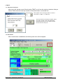
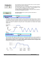
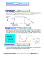
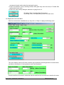
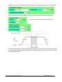
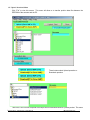
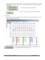
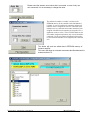
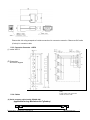
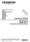
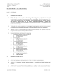
Mechatronics Cylinder
PC Tool Kit
TBVST Termi-BUS ®
Operation Manual
Document No.
MN1-MTX-00001B-NA
Ver.2.71 2002/10/21
Table of Contents
1. TBVST Termi-BUS® Tool Kit Summary ........................................................... 3
2. TBVST Termi-BUS® Tool Kit Installation ........................................................ 3
3. TBVST................................................................................................................. 4
3.1. Selection of serial port ---------------------------------------------------------------------------- 4
3.2. Main Menu --------------------------------------------------------------------------------------------- 4
JOG operation: ------------------------------------------------------------------------------------------------5
Menu bar: -------------------------------------------------------------------------------------------------------6
3.3. Position Data Save Menu ------------------------------------------------------------------------- 7
3.4. Display Data Conversion Menu ----------------------------------------------------------------10
3.5. Upload / Download Menu ------------------------------------------------------------------------12
3.6. Trace Menu -------------------------------------------------------------------------------------------13
4. CTA-1 ................................................................................................................ 15
4.1. Serial port selection -------------------------------------------------------------------------------15
4.2. Main Menu --------------------------------------------------------------------------------------------15
5. Appendix .......................................................................................................... 18
5.1. PC Tool Soft ware installation memo --------------------------------------------------------18
5.2. PC Tool Kit Parts (TBVST-EN-SET)-----------------------------------------------------------18
5.2.1.Contents of PC Tool, Model: TBVST-EN-SET ----------------------------------------------- 18
5.2.2. RS232C/RS485 Junction Converter Circuit ------------------------------------------------- 18
5.2.3. Connector Converter : ADP-2 ------------------------------------------------------------------- 19
5.2.4. Cables ------------------------------------------------------------------------------------------------- 19
.
Dyadic Systems – Mechatronics Cylinder Manual
.
MF-005500-EN-2/20
1. TBVST Termi-BUS® Tool Kit Summary
TBVST Termi-BUS® Tool kit is an operational and set up tool for Mechatronics Cylinder including
Termi-BUS® interface. TBVST Termi-BUS® Tool kit consists of 2 applications, TBVST and CTA-1.
TBVST is an easy-to-use operational and teaching tool which allows the Mechatronics Cylinder to be
programmed by GUI operation.
CTA-1 is a tool that allows direct editing of data on the Mechatronics Cylinder Servo Controller. With this
tool it is possible to use all functions of the Termi-BUS® Interface.
WARNING – PLEASE ENSURE YOUR ACTUATOR HAS 24VDC POWER BEFORE RUNNING
PCTOOL. RUNNING PCTOOL WITH AN UNPOWERED AXIS CONNECTED MAY RESULT IN
DAMAGE TO YOUR SERIAL PORT.
2. TBVST Termi-BUS® Tool Kit Installation
TBVST Termi-BUS® Tool kit is supplied on CD-ROM. On this CD-ROM you will find 2 zipped files,
DISK1 and DISK2. Please unzip them, execute Setup.exe in DISK1, and follow the installation
instructions.
If you experience any errors during the installation process please call Mirai Intertech at 905-763-9442.
After installation is complete, the TBVST Termi-BUS Tool Kit folder will be created in the Windows Start
menu as follows.
Before running Termi-Bus Tool Kit a Mechatronics Cylinder must be connected to your computer. Use
the components supplied to connect to a serial port on your computer.
.
Dyadic Systems – Mechatronics Cylinder Manual
.
MF-005500-EN-3/20
3. TBVST
3.1. Selection of serial port
After turning the Actuator power ON and starting TBVST you will see the serial port selection dialog as
follows. Please select the serial port number to which the actuator is connected now.
This number is PC serial port number to connect
with ADP-1. COM1 is 1, COM2 is 2.
After the selection of serial port number, please
press this set button. This will establish the
communication between PC and the actuator
connected to the serial port.
3.2. Main Menu
After communication is established, the following main menu will be displayed.
.
Dyadic Systems – Mechatronics Cylinder Manual
.
MF-005500-EN-4/20
Please select the actuator axis number that is connected. When only one axis is
connected, it will not be necessary to change this value.
The default axis number is 0 and it is written on the EEPROM memory in the controller
of the Mechatronics Cylinder. In case of a multi-axis connection, unique axis numbers
must be assigned for each axis. Therefore in case of multiple connection each actuator
must have been assigned with different axis numbers by using the CTA-1 application
software or CTA-23 Teach Pendant.
If Servo is not ON yet, please press this button to turn the servo ON, so that the motor
will be active.
Before initiating position teaching, please press this button to home the
actuator.
JOG operation:
The JOG operation bar can move the actuator to desired position. This feature can be useful for
teach-style programming (when the actuator has been jogged to the desired position, click the “Position
Data Save Window” Button – more detail in section 3.3).
Forward Limit
Return Limit
Stroke
Drag this square side to side with your mouse to
move the actuator at the positioning parameters
(speed & acceleration) of the current position.
Move the actuator by the minimum displayed conversion unit
by clicking this area. The Mechatronics Cylinder by default
displays units in mm, therefore the actuator will move by 1 mm
per click.
Move the actuator by the minimum unit of the encoder by clicking this square.
This motion can be multiplied by 10 or 100 using the radio buttons on the
right. By keeping this square pressed, the actuator will move continuously.
Use these radio buttons to control the distance the actuator moves with each click.
The actual position of the actuator is displayed underneath of the JOG bar as follows:
.
Dyadic Systems – Mechatronics Cylinder Manual
.
MF-005500-EN-5/20
In order to save position data to the actuator, please press
this button to open “Position Data Save Window”.
Please refer to “3.3. Position Data Save Menu”.
Saved position data can be executed by clicking the position number in the Position Run bar as follows:
Menu bar:
The menu bar has the following functions:
To end TBVST.
To display Help Menu
To display mechanical resolution & miscellaneous parameters.
Please refer “3.4. Display conversion set menu”
To open the menu of upload/download data between files in the PC and
Mechatronics Cylinder.
Please refer “3.5. Upload/Download menu”.
To open the trace menu for actual speed or position.
Please refer “3.6. Trace Display Menu”.
.
Dyadic Systems – Mechatronics Cylinder Manual
.
MF-005500-EN-6/20
3.3. Position Data Save Menu
When Position Data Save Menu is opened or Position No. is selected, the following question is displayed.
If “Yes” is selected, the actual current position of Mechatronics Cylinder shaft rod will be saved as the
target position (Position Teaching).
If “No” is selected, the target position data can be programmed in this menu by moving the slide bar or
data typing.
.
Dyadic Systems – Mechatronics Cylinder Manual
.
MF-005500-EN-7/20
After pressing the Position Data Save Menu button, the above question
dialog (Edit mode selection) will appear.
After answering this menu, the above data edit menu will appear showing
the current position number of the actuator. The data displayed on this
screen is stored in the EEPROM memory of the actuator.
If another position is selected, the data for that position will be read from
the actuator and displayed in this menu.
After editing parameters for a position, press the save button to
save the new data.
The “Relative” option under “Position Command” is used to identify of Incremental movement. If this box
is checked, the “Position Command” becomes the increment by which the cylinder will move when it
receives the start signal for that step. By using this incremental movement a Mechatronics Cylinder can
execute more than 16 positions as long as some of the positions are executed with constant
displacement.
The “At position width” parameter allows the user to customize the distance from motion completion at
which the actuator outputs the position complete signal. The default data is about 4 pulses pitch in mm. A
larger setting for “At position width” would for example enable the actuator to make a continuous motion
with several different speeds. The completion signal would be sent before the axis is stopped, which
would allow a new position to be executed without stop.
.
Dyadic Systems – Mechatronics Cylinder Manual
.
MF-005500-EN-8/20
This data entry box allows speed to be set for a given position.
The acceleration set in this box is by default applied to both the start and finish of motion for a given
position. The “Max. Acceleration” selection box tells the axis to move as quickly as possible at the start of
motion and use the identified acceleration rate to reduce velocity at the end of motion.
This menu specifies the gain used to drive the servo to the given position. There is no unit of
measurement for this. The max. gain is 15, and the default setting is 6. Usually there is no need to
change this data, but if fast positioning time is critical, it may be possible to reduce positioning time by
changing this value to finely tune the servo control parameters to your load. See section 3.6 (Trace
Mode) for further detail on testing the effects of different servo gain settings.
If the “Pusher Valid” check box is marked, Push Force Mode will be used for the given position. This
mode consists of an approach movement and a Push Force movement.
• Approach movement data: Set Position, Speed and Acceleration (same as regular positioning).
The approach position is the position where Push Force movement starts.
• Push Force movement will start from the approach position if the current position is before the
approach position. If the current position is past the approach position already, the axis will immediately
.
Dyadic Systems – Mechatronics Cylinder Manual
.
MF-005500-EN-9/20
commence the push motion when the start signal is given.
• Push Force direction is set by selecting Reverse Side (push away from motor end) or Forward Side
(push towards motor end).
• Push Force can be set by sliding the select bar or typing force in %.
By clicking “Save”, the edited data will be saved.
By clicking “Close”, the display will go back to the main menu.
3.4. Display Data Conversion Menu
After the communication establishment you may click on “SetUp” to display the following menu.
This menu displays values for Encoder resolution and mechanism positioning distance conversion data,
and allows customization of Homing behavior and Zone Boundaries.
Encoder resolution unit and axis mechanical data are read from the connected axis, therefore this menu
.
Dyadic Systems – Mechatronics Cylinder Manual
.
MF-005500-EN-10/20
is display only and it is not necessary to edit the settings. The cancel button returns to the main menu.
This menu will select the home position. Forward end and backward end positions are available.
This menu will set the profile of the homing motion.
This function energizes the “Zone” signal when the actuator is in the zone defined by these end points.
Units are shipped with the forward boundary set to zone signal start position, and reverse boundary set to
zone signal end position.
.
Dyadic Systems – Mechatronics Cylinder Manual
.
MF-005500-EN-11/20
3.5. Upload / Download Menu
Click “File” to view this screen. This menu will allow us to transfer position data files between the
EEPROM of the actuator and the PC.
These buttons select Upload operation or
Download operation.
Termi-Bus Tool Kit comes complete with sample files for each Mechatronics Cylinder product. This menu
.
Dyadic Systems – Mechatronics Cylinder Manual
.
MF-005500-EN-12/20
is used to select the file to upload or download. To transfer setup data from the axis to your PC simply
type the name of the file you want to save it to (without extension) in the “File Name” box and click
“Upload Start”.
These buttons start uploading or downloading.
or
By clicking “Close”, the display will go back to the main menu.
3.6. Trace Menu
This function allows the user to display and print the behavior for the last movement sequence of the axis
(shown as speed or position vs. time).
Click this button to display a graph of the last axis movement according to
the settings chosen in the “Trace Set” menu.
.
Dyadic Systems – Mechatronics Cylinder Manual
.
MF-005500-EN-13/20
To close the trace menu and go back to main.
To print out the displayed trace curve.
To save the displayed trace curve in a file.
To read and display a saved trace curve.
To clear the displayed trace curve.
To edit the trace display set up. After a change, these settings become effective from next trace.
Trace set (D):
the graph.
To select the trace type (velocity or position) and the scales of the X and Y axes of
To set the maximum value of the vertical axis of the curve.
To set the maximum value of the horizontal time axis of the
curve.
To save the trace profile settings and go back to the Trace menu.
Changed settings will be effective from the next trace execution.
.
Dyadic Systems – Mechatronics Cylinder Manual
.
MF-005500-EN-14/20
Cancels the data edit and closes this display (returns to Trace menu).
4. CTA-1
4.1. Serial port selection
After turning the Actuator power ON and starting TBVST, the first menu displayed is the serial port
selection dialog as follows. Please select the serial port number that connects with the actuator now.
This number is PC serial port number to
connect with ADP-1. COM1 is 1, COM2 is 2.
After selecting the serial port number, please
press the set button. This will establish
communication between the PC and the
actuator connected to the serial port.
4.2. Main Menu
After communication is established, the following main menu will be displayed.
.
Dyadic Systems – Mechatronics Cylinder Manual
.
MF-005500-EN-15/20
Please select the actuator axis number that is connected. In case of only one
axis connected, it is not necessary to change this value.
The default axis number is 0 and it is written on the
EEPROM memory in the controller of the Mechatronics
Cylinder. In case of a multi-axis connection, unique axis
numbers must be assigned for each axis. Therefore when
multiple axes are connected each actuator must have been
assigned with different axis numbers by using this CTA-1
application software or the CTA-23 Teach Pendant. At the
axis number assignment operation, only one axis should be
connected. Use the axis number assignment selection box
to select the desired number to be assigned to the connected
axis.
This button will save the edited data to EEPROM memory of
Actuator amplifier.
This menu will allow us to transfer movement data files between the
actuator and the PC.
.
Dyadic Systems – Mechatronics Cylinder Manual
.
MF-005500-EN-16/20
This button will select Upload operation or Download
operation.
This menu allows the user to specify the desired filename for a download.
The file extension is not required.
These buttons start uploading or downloading.
or
By clicking “Close”, the display will go back to the main menu.
.
Dyadic Systems – Mechatronics Cylinder Manual
.
MF-005500-EN-17/20
5. Appendix
5.1. PC Tool Software Installation Memo
If you experience any problems installing the Termi-Bus ToolKit on your PC please contact Mirai
Inter-Technologies.
5.2. PC Tool Kit Parts (TBVST-EN-SET)
PC Tool is a single axis support tool to program Mechatronics Cylinder through PC display with jogging
and other set ups. The software is supplied on CD-ROM.
5.2.1.Contents of PC Tool (TBVST-EN-SET)
(see red circle in the following figure)
① PC Software:
TBVST-EN
(to install it in PC)
② RS232/RS485 Converter:
ADP-1
(to connect with PC serial port)
③ Connector Junction:
ADP-2
(Junction for cables)
④ ADP Cable (1m):
RP9050-010
(to connect Mechatronics Cylinder and ADP-2)
⑤ SIO Cable (1m):
RP9041-010
(to connect ADP-1 and ADP-2)
PC Set Tool Kit (TBVST-EN-SET)
Connect with DC24V Power Supply
Connect ILLK terminal with +24V
Programming software
(TBVST-EN)
SIO Cable, 1m
(RP9041-010)
ADP Cable, 1m
(RP9050-010)
Connector Converter
i
ADP-2
RS232/485 Converter
(ADP-1)
Tool kit Circled in Red
5.2.2. RS232C/RS485 Junction Converter Circuit
(Model: ADP-1)
(1) Model No.:
ADP-1
(2) Dimensions
.
Dyadic Systems – Mechatronics Cylinder Manual
.
MF-005500-EN-18/20
Please refer 4.4. wiring examples of outside connections for connector connection. Please use SIO cable
(6 wires) for connector cable.
5.2.3. Connector Converter : ADP-2
(1) model: ADP-2
(2) Dimensions
and circuit diagram
5.2.4. Cables
(Note)
In case of ADP-2 use, please use
at least one axis on CN2.
(2) Serial connector cable (model: RP9050-030)
(applicable for any Mechatronics Cylinders)
.
Dyadic Systems – Mechatronics Cylinder Manual
.
MF-005500-EN-19/20
1
2
3
4
+5V
TRx+
5V
TRx-
Connector
Socket
Plug
Red
White
Black
Green
Made by AMP Co.
172167-1
170365-1
Manufactured by:
Ni-66-3 Kanaiwa Honmachi, Kanazawa
Ishikawa-Ken, 920-0336 Japan
Tel: 81-76-267-9103, Fax: 81-76-267-9104
Imported by:
Mirai Inter-Technologies Systems Ltd.
35 Pollard St.
Richmond Hill, ON, L4B 1A8 Canada
Tel: 905-763-9442
Fax: 905-731-3165
.
Dyadic Systems – Mechatronics Cylinder Manual
.
MF-005500-EN-20/20