1
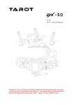
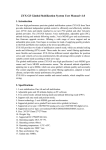
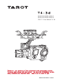
T4-3d
SPORTS GOPRO HERO 3
SPORTS GOPRO HERO 4
2015.7.1 User Manual V1.00
Thanks for your purchase of Tarot professional aerial photography products.
To ensure your success with this product, we would like to introduce the following information and important notes ,hope it can be useful for you.
www.tarotrc.com
T4-3d
ASSEMBLY SECTION
组装说明书
Contents
Warning and Disclaimer . . . . . . . . . . . . . . . . . . . . . . . . . . . . . . . . . . . . . . . . . . . . . 2
Product Introduction、Specifications . . . . . . . . . . . . . . . . . . . . . . . . . . . . . . . . . . . . . 3
I. Product List . . . . . . . . . . . . . . . . . . . . . . . . . . . . . . . . . . . . . . . . . . . . . . 4
II. Mounting & Configuration . . . . . . . . . . . . . . . . . . . . . . . . . . . . . . . . . . . . 5
1. Gimbal Controller Wiring Diagram & Descriptions .........................5
2. Gimbal Working Mode .......................................... ...6
3. Working Mode Setup ............................................. 6
III. Flight Test ................................................ 7
IV. ZYX T-3D Assistant Software ................................... 7
1. Drive & PC Assistant Software Installation and Setup . ................ 7
2. Introduction ........................................... 7
3. Basic Setup ...........................................8
4. Channels ............................................ .9
5. Tools ................................................9
6. Firmware Update ........................................9
V . Troubleshooting . .. ................. ...... .................10
VI . Port Descriptions . . . . . . . . . . . . . . . . . . . . . . . . . . . . . . . . . . . . . . . . . . 1 0
VII . LED Indicators . . . . . . . . . . . . . . . . . . . . . . . . . . . . . . . . . . . . . . . . . . . 1 1
Warning
警 告
The state intellectual property has been awarded the TAROT model.,ltd more patents. Any units orindividual
without the license holder manufacture 、copy 、use and sale the product will be patent lawsuit.
国家知识产权已授予TAROT航模有限公司此产品多项专利权.任何单位或个人未经持有者授权许可,制造、仿
造、使用、销售此产品将会面临专利侵权诉讼.
1
塔 罗 航 空 科 技 有 限 公 司
TA R O T AV I AT I O N T E C H N O L O G Y C O. , LT D
T4-3d
ASSEMBLY SECTION
组装说明书
Warning and Disclaimer
Please DO NOT adjust the gimbal or change its mechanical structure!
Before leaving the factory, T4-3D gimbal has been adjusted to fit the
camera. Based on the setup procedures, you can achieve a fabulous flight
experience. Please do not adjust the gimbal or change its mechanical structure. Moreover, do not add any external component to the camera. It is
highly suggested to apply to the original battery to avoid malfunctions of
internal wirings or performance degradations.
In order to ensure the safety after powering up, we recommend you to
remove allthe propellers. Keep the entire components far from children
and flammable & combustible materials!
Because we have no control of the use, mounting, assembly and modification processes, TAROT will not assume any legal responsibility for the injury or damage.
T4-3D ONLY supports GoPro Hero 3
GoPro Hero 4
Warning
警 告
The state intellectual property has been awarded the TAROT model.,ltd more patents. Any units orindividual
without the license holder manufacture 、copy 、use and sale the product will be patent lawsuit.
国家知识产权已授予TAROT航模有限公司此产品多项专利权.任何单位或个人未经持有者授权许可,制造、仿
造、使用、销售此产品将会面临专利侵权诉讼.
2
塔 罗 航 空 科 技 有 限 公 司
TA R O T AV I AT I O N T E C H N O L O G Y C O. , LT D
T4-3d
ASSEMBLY SECTION
组装说明书
Product Introduction
T4-3D a great 3-axis gimbal for model aircraft enthusiasts, can be widely applied to
various model aircraft activities and entertainments. With unique internal wiring design,
built-in IMU gimbal control module, specialized servo drive module, this gimbal is able
to support Pan Follow (PF) mode and First Person View (FPV) mode. Moreover, video
out and battery charging of GoPro Hero 3 can be achieved through T4-3D.
Specifications
Input Power
3S-6S Li (11V-26V)
30mA(@25V)
Working Current
50mA(@12V)
350mA(@25V)
Stall Current
700mA(@12V)
-20℃~+50℃
Working Environment
178g
Weight
Dimensions(Lx WxH)
99mmx88.5mmx105.6mm
TILT:±200度/秒
Max Controllable
Rotation Speed
ROLL:±200度/秒
PAN:±200度/秒
TILT:-120度~ +15度
Controllable Rotation Range
±0.02度
Attitude Control Accuracy
Supported Camera
GOPRO HERO 3
Assistant Software
Supporting Platform
Windows XP/VISTA/7/8
3
塔 罗 航 空 科 技 有 限 公 司
TA R O T AV I AT I O N T E C H N O L O G Y C O. , LT D
T4-3d
ASSEMBLY SECTION
组装说明书
一. 产品清单
1.
Product List
Gimbal * 1
With unique internal wiring design, built-in
IMU gimbal control module, specialized
servo drive module, this gimbal is able to
support Pan Follow (PF) mode and First
Person View (FPV) mode.
Main Components Pack
Gimbal Main Controller Module*1
5V OUT & Receiver & AV Cable*1
Gimbal Main Controller & Gimbal Connection Cable*1
USB Module Cable*1
Connection Cable to Flight Controller*1
4
塔 罗 航 空 科 技 有 限 公 司
TA R O T AV I AT I O N T E C H N O L O G Y C O. , LT D
T4-3d
ASSEMBLY SECTION
组装说明书
II.Mounting & Configuration
1.Gimbal Controller Wiring Diagram & Descriptions
Wiring Diagram
Descriptions:
Battery
Receiver
Power Supply:3S-6S Li (11V-26V)
* If you choose a battery to power up the gimbal and multi-rotor, please
make sure this battery meets requirements of both components.
1.Conventional Receiver: connect it to the CH1/SBUS and CH2 Channel in the gimbal main
controller. Also, set Receiver Type and corresponding channel in the assistant software.
2.FUTABA SUBS or SBUS-2: connect it to CH1/SBUS channel in the gimbal main controller.
MAKE SURE CH2 IS UNCONNECTED . Also, set Receiver Type and corresponding channel in
the assistant software.
3. If you have 5V power supply to the receiver, please disconnect the 5V power of
CH1/SBUS channel (RED Cable).
Video
Flight
Controller
Camera
Connect the video wireless transmission module to AV OUT port. DO NOT
misconnect signal and video cable.
Gimbal can work independently without Tarot ZYX-M Flight Control Module, but its
performance might be influenced. For instance, angle offset might occur when
the accelerated state lasts for a long time.
If you are pursuing a perfect performance, please connect the gimbal and Tarot
ZYX-M Flight Control Module to the DATA/FC channel of gimbal controller
through the special cable in main components pack.
The gimbal will connect the camera through “GoPro Charging & AV-OUT Cable”.
5
塔 罗 航 空 科 技 有 限 公 司
TA R O T AV I AT I O N T E C H N O L O G Y C O. , LT D
T4-3d
ASSEMBLY SECTION
组装说明书
2. Gimbal Working Mode
You should select a three-positioned or two-positioned switch in R/C for working mode.
Please connect the corresponding port of the receiver to CH1/SBUS or CH2 of the
gimbal controller. Also, set RC MAPPING in the assistant software. For different
positions, use endpoint fine tune function to set. Please refer to the MODE Channel
section in assistant software for detailed information.
Attentions:
When the MODE port is unconnected, the gimbal can only work in the DEFAULT mode.
Moreover, during flight, if the MODE is unconnected suddenly, the working mode would
remain the same before disconnection.
After powering up the gimbal, if the receiver is unconnected, it works on DEFAULT MODE.
Descriptions about working mode:
Pan Follow (PF) Mode
FPV Mode (First Person View)
Descriptions
The angles of Roll and Pitch
keep unchanged, while the
angle of Pan axis changes
according to the head of the
multi-rotor.
The angles of Roll, Pitch and Pan
axis change according to the
attitude of the multi-rotor.
Tx Control
Under Control
Under Control
Attitude Stability
Vibration
Reduction
3.Working Mode Setup
Choose a two-positioned or three-positioned switch:
Take the three-positioned switch as an example: Position 1 refers to FPV Mode; Position 3
corresponds to AL Mode. Position 1 and Position 3 can be exchanged.
6
塔 罗 航 空 科 技 有 限 公 司
TA R O T AV I AT I O N T E C H N O L O G Y C O. , LT D
T4-3d
ASSEMBLY SECTION
组装说明书
III.Flight Test
Steps:
1. Please ensure all the wirings are correct and the power supply is in great condition.
2. Turn on the transmitter.
3. Powering up the gimbal and keep it still. After self-check, gimbal angle corresponds to
INIT ANGLE in the assistant software.
4. Switch from different working modes to check the rotation direction in ROLL, PITCH,
and PAN axis.
Attentions:
Before flight test, please ensure:
1 . Correctly mount the camera into the gimbal and the gimbal onto the multi-rotors.
2 . All the wirings are correct.
3 . The camera and transmitter have correctly set.
Gimbal Self-check:
1. After powering up the gimbal, it enters self-check procedure. When RED & BLUE lights
flash twice at the same time, self-check finishes.
2. When self-check finishes, gimbal angles corresponds to INIT ANGLE in the assistant software.
IV. T4-3D Assistant Software
1. Drive & PC Assistant Software Installation and Setup
①Please download the drive and PC assistant software from http://www.t arotrc .com/
②Run the drive program under USB Driver folder, and finish the installation procedures step by step.
Windows x86: “CP210xVCPInstaller_x86.exe”;
Windows x64: “CP210xVCPInstaller_x64.exe”;
③Connect the USB module to the computer, and finish the installation.
④Run the assistant software ZYXT-3D.EXE and set parameters.
2. Introduction
T4- 3Da three-axis gimbal, could support the camera to stabilize its positions on the roll, tilt and pan axis.
You could adjust receiver type, working mode, angle range and other options in the assistant software.
First of all, please connect gimbal controller to the PC through a USB cable. Choose a correct
COM port and click the “Connect”.
If the connection is successful, the gimbal would stop rotating to protect your device.
After parameters setup finishes, click “Run Gimbal”. Push sticks and toggle switches to
ensure the gimbal works correctly.
When gimbal configuration finishes, you should click "Write Flash" to ensure all the
parameters have written to the gimbal. Next time, the gimbal will automatically run
the parameters you have saved in the flash.
7
塔 罗 航 空 科 技 有 限 公 司
TA R O T AV I AT I O N T E C H N O L O G Y C O. , LT D
T4-3d
ASSEMBLY SECTION
组装说明书
3. Basic Setup
Methods to Connect the Receiver:
1. Conventional Receiver: connect it to
the CH1/SBUS and CH2 Channel in the
gimbal main controller.
2. FUTABA SUBS or SBUS-2: connect it to
CH1/SBUS channel in the gimbal
1. Receiver Unconnected: set gimbal
mode in Default Mode of assistant software.
2. Receiver Connected: set gimbal mode
in MODE channel of the receiver.
FPV Mode: The direction of the gimbal and
directions (roll, tilt and pan) of the
multi-rotor are the
Init Angle stands for the initial angle of each
direction after the gimbal has been powered
up. For instance, if you want the tilt direction
of the camera is on -45 degree, you should
enter -45 on the corresponding box.
Angle Range of Roll: -25°~25°
Angle Range of Tilt: -120°~15°
Angle Range of Pan: -125°~125°
Please press “ENTER” button after
modifying the parameters.
Angle Range of Rotation on each Direction
of the Gimbal
If the gimbal rotates to or over the extreme
value, it would stop rotating until the value
goes within the range.
The Extreme Range of Roll: -25°~25°
The Extreme Range of Tilt: -120°~15
The Extreme Range of Pan: -125°~125°
Please press “ENTER” button aft
It relates to the response speed of the gimbal.
When it becomes too small, the stability
deteriorates. When it turns too large,
self-oscillation occurs.
Methods to adjust: if vibration occurs,
please decrease the parameters until it
disappears.
Input Range: 0~200
Please press “ENTER” button after
The maximum rotation speed the gimbal can reach.
modifying the parameters.
When pushing sticks to the maximum but the
Attention: it has been adjusted to an
rotation speed is lower, you could increase the
value of Max Rotation Speed to enhance the
rotation speed;
When pushing sticks gradually but the rotation
speed is too fast, you could decrease the value
to slow down the speed.
Max Rotation Speed Range of ROLL: 0~200(degree/sec)
Max Rotation Speed Range of TILT: 0~200(degree/sec)
Max Rotation Speed Range of PAN: 0~200(degree/sec)
8
塔 罗 航 空 科 技 有 限 公 司
TA R O T AV I AT I O N T E C H N O L O G Y C O. , LT D
T4-3d
ASSEMBLY SECTION
组装说明书
4. Channels
(1)RC Mapping
Tilt Channel
Push the stick, and observe the rotation direction of the gimbal and
the moving direction of the cursor
Mode Channel:This channel controls gimbal working mode.
Choose a three-positioned or two-positioned switch to control the
working mode of the gimbal. Map it into Mode Channel.
Toggle the switch to the position, the cursor should be in the
corresponding area.
FPV Mode: the direction of the gimbal and directions
(roll, tilt and pan) of the multi-rotor are same.
PF Mode: the head of the multi-rotor and the gimbal are in the
same direction.
(2)Control Mode
Methods to control gimbal rotation by R/C (tilt only).
Push sticks to observe the moving direction of the cursor
and rotation direction of the gimbal.
Rate Mode:The position of the stick is corresponding to
the rotate speed of the gimbal.
Angle Mode:The position of the stick is corresponding to
the angle of the gimbal.
5. Tools
Please calibrate sensors when the output of gyro is far from zero while
the gimbal is stationary.
Methods to calibrate
It is necessary to keep the gimbal in the stationary state. Click
"Calibrate Sensors". When "Calibration is successful" shows on
status bar, the calibration procedures finishes.
6. Firmware Update
9
塔 罗 航 空 科 技 有 限 公 司
TA R O T AV I AT I O N T E C H N O L O G Y C O. , LT D
T4-3d
ASSEMBLY SECTION
组装说明书
Update Procedures:
( 1)Please make sure the connection between gimbal control module and PC are correct, and
check whether or not the module version can be seen.
( 2)Please connect the DATA/FC of module and PC through a USB cable
( 3)Click for upgrade. Wait until all the procedures have been done.
Attention:
If something wrong occurs during update, please check the connection and power supply.
Also, make sure you have correctly installed the drive program. You can repeat upgrading
for several times until your device is broken.
Moreover, you could screenshot the upgrade procedures and send your concerns or
problems through the feedback on the top right corner of the assistant software.
V. Troubleshooting
Angle is
not level
1. Error of sensors is too large.
2. Tx is not centered.
1. Calibrate sensors.
2. Center the Tx.
Gimbal
vibrates.
1. The camera is not screwed down.
2. Motor torque is too large.
1. Screw down the camera and lens screws.
2. Decrease motor torque value slightly.
1. Vibration is too large;
Image of the
2. Damping balls are not fixed.
video is not
stable enough. 3. Motor torque is too small.
1. Reduce the vibration of the multi-rotors;
2. Tightly fix the damping balls.
3. Slightly increase the value of motor torque.
1. Check and fix the wiring cables;
Red light
blinks quickly.
1. Connection cable between gimbal
controller and its main body becomes loose. 2. Make sure whether or not there is
2. Gimbal stall protection goes far
resistance to gimbal rotation. Then,
beyond ten times.
power cycle the gimbal.
VI. Port Descriptions
Gimbal Main Controller Port
PWR
DATA/FC
5V/RC/AV
Power Port
Gimbal Main Controller Assistant Software Update & Gimbal Data Input Port
5V Power Output & Receiver Input & AV-OUT Port
Motor Drive & Sensor Module Port
DEBUG
Debug Port. Do not connect it to any external device.
10
塔 罗 航 空 科 技 有 限 公 司
TA R O T AV I AT I O N T E C H N O L O G Y C O. , LT D
ASSEMBLY SECTION
T4-3d
组装说明书
VII. LED Indicators
Gimbal Main Controller LED Indicators Status
RED & BLUE lights blink twice.
RED & BLUE lights are constantly on.
BLUE light turns off.
POST (Power On Self-Test) Status.
POST (Power On Self-Test) fails.
Flight Controller Disconnects.
BLUE light is constantly on.
BLUE light blinks.
Flight Controller Connects.
Flight Controller connects and flight data are available.
1. Line Fault.
RED light blinks.
2. Gimbal stall protection goes far beyond ten times.
Motor Drive & Sensor Module Indicators Status
BLUE light blinks once.
POST (Power On Self-Test) Status.
BLUE light is constantly on.
11
POST (Power On Self-Test) fails.
塔 罗 航 空 科 技 有 限 公 司
TA R O T AV I AT I O N T E C H N O L O G Y C O. , LT D