1
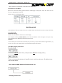
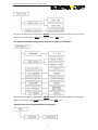
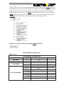
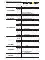
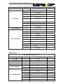
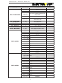
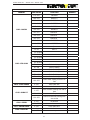
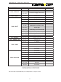
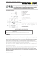
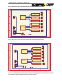
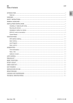
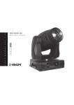
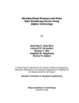
USER MANUAL
Beam 300
Beam 700
USER MANUAL - BEAM 300 / BEAM 700
USER MANUAL - BEAM 300 / BEAM 700
CONTENTS
1.
Safety Instruction………………………………………...….…………………01
2.
General Guidelines………………………………………..….………....... ….01
3.
Technical Specification………………………………………..….……………02
4.
Safety Operations…………………………………….……………................03
5. Connection of Fixtures…………………………………………..................04
6.
Control Mode……………………………………………………………...........05
6.1 DMX Addressing……………………..….……………………..…..........06
6.2
7.
LCD
Menu Display Instruction……………………………………..07
DMX Channe Assignments…………………………………….………………08
8. Installation of Fixtures…………………………………………..................13
9.
Maintenance an d Cleaning…………………………………………………….14
10. Wiring Diagram……………………..….……………………..…................15
USER MANUAL - BEAM 300 / BEAM 700
Thank you for purchasing our product
SAFETY INSTRUCTION
For your own safety, please read this user manual carefully before installing the device.
Caution!
Be careful with your operations. With a dangerous
voltage you can suffer a dangerous electric shock
when touching wires!
Keep this manual for future needs
-Be carefully read this user’s manual before install and operate
-Itisabsolutelynecessaryfortheusertofollowthesafetyinstructions
-Make sure all staffs related with installation, operation, and carriage and warehouse are qualified.
-Please check carefully that there is no damage caused by transportation. Should be any dam one,
consult your dealer and don’t install this device.
Caution!
Keep this device away from rain and moisture!
Unplug mains lead before opening housing!
The applicable voltage for the lighting is between AC110-240V 56-60Hz / Electronic ballast,
230V/50Hz/Magnetic ballast. Never use it when thundering and make sure it installing and
operating this device on the applicable temperature between -5 °C ~ 45 °C, thereinnohighly
inflammable material within a distance of min.1.5m. While choosing the installation-spot, please
make sure that the device is not exposed to extreme heat, moisture and dust.
GENERAL GUIDELINES
Warning!
Operate the device only after having familiarized with its functions. Do not permit
operation by person not qualified for operating the device. Most damages are result of
unprofessional operation!
-If this device will be operated in any way different to the one described in this manual, the product
may suffer damages and the guarantee becomes void. Furthermore, any other operation may lead
to dangers like short-circuit, burns, electric shock, burns due to ultraviolet radiation, lamp
explosion, crash etc.
-Read the instructions carefully before turning on the power or install this device, in order to
maintain this condition and ensure a safe operation, it is absolutely necessary for the user to follow
the safety instructions, and warning notes written in this manual。
Keep yourself and others from electric shocks。
-Disconnect to the fixture from AC power before change to lamp, fuse and no any equipments are
1
USER MANUAL - BEAM 300 / BEAM 700
operating.
-For protection from electronic shock, the fixture must be earthed!
-Install a suitable plug on a power cord, install overload devices. The earth has to be connected!
Prevent you and the safety of others by ultraviolet radiation and lamp explosion.
-Do not operate the moving head light with strong light without optical lens filter and can be
released directly.
-Danger! Install the lamp with the device switch off only. Make sure the temperature of light body
should not be obviously higher than the surrounding temperature.
Noted that change lamp, leave the device switch off until it has reached to room temperature.
-Avoid looking directly into the light source when the fixture was put power on.
Prevent you own and others burn or installation-spot catch fire.
-Avoid to both TDS (temperature detect switch) and fuse direct shock-circuit, for placement use
TDS and fuses of same type and rating only.
-Fixtures cannot be installed on combustible substances (alcohol, gasoline and paper), keep more
than 1m distance with wall for smooth air flow, so there should be no shelter for fans and
ventilation for heat radiation.
-The minimum distance between light output and the illuminated surface must be more than 1
meter.
-Never installation optical filter and others on the internal 3-lens.
-If the device has been exposed to drastic temperature fluctuation (e.g. transportation), do not
switch it on immediately. The arising condensa tion water might damage your device. Leave the
device switched off until it has reached room temperature.
-Please use original packaging if the device is to be transported. For safety reasons, please be
aware that all modifications on the device were forbidden.
-The maximum ambient temperature 40℃ must never be exceeded.
Prevent you own and the safety of others by the device was crashed.
-Never lift the fixture by holding it by oneself.
-Always fix the fixture with an appropriate safety rope and holder.
-Anytime, installing and taking down the fixture, when rigging, de-rigging or servicing the fixture
staying in the area below the installation place, on bridges, under high working places and other
endangered area is forbidden.
TECHNICAL SPECIFICATIONS
-Light Source: Philips MSR 300 FASTFIT
-Input voltage: AC100-240 50-60Hz
-Control channels: 16/24CH
-XY Movement: Pan 540°(16 bit), Tilt 280°(16 bit)
-CMY color mixing system
-Color Wheel: 8 replaceable colors plus white, bi-direction revolving rainbow effects available
30 preset CMY color mixing wheels and color macro-asynchronous available
2
USER MANUAL - BEAM 300 / BEAM 700
-Rotating Gobo Wheel: 6 replaceable colors plus white, with shaking function and random position
function available
-Prism: 3-facet prism, forward and reverse rotation available and reposition function
-Strobe: variable strobing 10 flash per sec, inside strobe macro-function
-Dimmer: 0~100% linear adjustable
-Frost: 0~100% linear adjustable
-LCD Display: displaying brightness adjustable (0~100%)
-Electronic ballast: auto energy saving and environmental protected
-Electronic Ballast: AC100~240V, 50/60HZ
-Magnetic Ballast: 230V/50Hz
-Dimension: 539×440×450mm
-Net weight: 25Kg
SAFETY OPERATIONS
This device has left our premises in absolutely perfect condition. In order to maintain this condition
and to ensure a safe operation, it is absolutely necessary for the user to follower safety instructions.
Don’t permit to operation by persons not qualified for removal or replace to the internal spare
parts( machine parts and original PCB).It shall be exclusively replaced by the manufacturer or his
service agent or a similar qualified person in order to avoid hazard. Please contact with dealer if
have some problems.
Please be aware that damages caused by manual modifications to the device are not subject of
warranty.
The lamp
-For the installation, it fits with Philips MSD GOLD 300/2 Mini FastFit, or Philips MSR Gold 300/2 Mini
FastFit. This high energy arc light with stable color temperature 8200K, color reproduce index is
more than 90, and the working life up to 2,000hrs, or 750hrs.
Warning!
-Make sure use lamp of same type only.
The lamp life expectancy is 2,000hrs, or 750hrs. For safety concerns, please replace a new lamp
when the used average life span of lamp more than 125% (940 hours).
Before replacing the lamp, make sure the lamp cools down.
Replacing lamp
Warning!
-During installation of halogen lamps, do not touch the glass bulb with hand. Please consult dealers
for right way to installing the lamp.
-Make sure your hands are clean when cleaning the lamp. Always use alcohol wiping and use a cloth
to handle the lamp during insert or removal, do not touch it until the alcohol volatilized completely.
Please get right instructions to installing the lamp from dealers.
3
USER MANUAL - BEAM 300 / BEAM 700
Installing or replacing the lamp
CAUTION!
Be careful with your operations. With a dangerous
voltage will suffer burn, caused fire!
-Please notice that the lamp is not a hot-restrict type, and wait approximately 15 minutes after
having turned off the lamp before you can turn it back on again.
-Make sure switch off before installation or replace the lamp. Never touch it by bare hands when
installing or replacing. Please use a Philips MSD GOLD 300/2 Mini FastFit or Philips MSR GOLD
300/2 Mini Fastfit, replacing it use same type too.
-Unscrew Screw marked A on the back of lamp-holder, it used to remove the lamp panel to
replace the lamp. It is can reach an excellent effects to fine-tuning screw on the back of lamp panel
mark X, Y and Z, which used for adjust to the lamp.
Connection of Fixtures
Notice!
Connect one signal input with one signal output.
This fixture is equipped with 3-Pin XLR Sockets for DMX Input and output. Re 3 Pin DMX in & out XLR
Socket, Pin 1 refers to Ground, Pin 2: Signal-, Pin 3: Signal + (as Graphs below):
DMXOutput
DMXInput
-The signal sockets are wired in parallel: one input, one output.
Mounting the device
-DMX512 always used STP (shielded twisted pair). Please advice use big cable or install DMX
distributor during long distance use standard cable.
-Do not separate one DMX Output into two Outputs.
-Do not connect overloaded. The max connected BEAM300 in each DMX Chain is 32 pcs.
-There should be a terminator on the last unit of DMX line. A terminator is a 120 ohm 1 watt resistor
which is a connection between Pin 2 and Pin 3 of a Male XLR connector. Using a cable terminator
will decrease the possibility of erratic behavior.
DMX512 Connection
-Please connect 3-pin XLR connector to 3 Pin socket for DMX IN
-And DMX OUT of former fixtures connects to DMX IN of the next fixture in the DMX Chain with the
same compatible DMX Cable in the DMX-output of the fixture.
4
USER MANUAL - BEAM 300 / BEAM 700
-There should be a terminator on the last unit of DMX Chain.
Connection to the Mains
Before use this fixture safely, please install a suitable plug on the power cord, and make sure the
fixture is appropriately earthed.
Please refer to the following table:
CONTROL MODE
DMX address of fixtures ranges from 001-504/488.Please note that the maximum range should not
exceed 504/488.
DMX Addressing
Please set DMX Address of fixture on LCD Display
For example, selecting 16BIT MODE 1, then the DMX Address of the first light is 001 (001-024).
The second one will display 017(015-039), and so on.
Caution:
It’s necessary to insert the XLR terminator (by connecting a 1/4W 120Ω between signal PIN-2/ +3)
on the last fixture of a DMX Chain to avoid possible signal interference.
LCD Menu Display Instruction
Function Mode:
Press button ENTER to enter Menu, and press button ESC back to display setting:
There are corresponding submenus for specific function under the main menu. For details, please
refer to Graph below:
-It is used to set DMX Address of fixtures from 0-511.
-It displays fixture Info.
5
USER MANUAL - BEAM 300 / BEAM 700
After entering above Menu, please button ENTER to enter, turn the Rotating Wheel to make specific
Selections, and press button Enter to confirm, or button ESC to exit.
This menu is to modify running mode or operation status of this fixture.
After entering above Menu, please button ENTER to enter, turn the Rotating Wheel to make specific
Selections, and press button Enter to confirm, or button ESC to exit.
-Use this menu to run a special demo-test sequence.
6
USER MANUAL - BEAM 300 / BEAM 700
After entering above Menu, please button ENTER to enter, turn the Rotating Wheel to make specific
Selections, and press button Enter to confirm, or button ESC to exit.
-Use this option in order to switch On/Off the lamp manually.
After entering above Menu, please button ENTER to enter, turn the Rotating Wheel to make specific
Selections, and press button Enter to confirm, or button ESC to exit.
-Select this menu, fixtures can be controlled manually. The definition of each channel is
as below:
DMX CHANNELS:
After entering above Menu, press button ENTER to enter, turn the Rotating Wheel to make specific
Selections, and press button Enter to confirm, or button ESC to exit.
Procedure:
-Select the program and press ENTER, Press【UP】or【DOWN】to select the program you wish
CH1---PAN(a coarse pan movement),by pressing ENTER again to display:
7
USER MANUAL - BEAM 300 / BEAM 700
X
:000
-Change the value from 0-255 via the Rotating Wheel to select the effect; press ENTER, reserve the
value (After exit the menu, all the DMX value will be 0); When there is DMX signal, the manual mode
always has the priority, When exit the manual mode, the fixture will be back to the DMX value.
-Select the program you wish and press ENTER. The selected program starts running. By Pressing
ENTER again is possible to pause the program running. You can exit every mode by pressing the
Mode/ESC-button. The function provided is described in the following sections:
Accessed to the menu as above, by pressing ENTER and display:
DMX CHANNEL Assignments
MODE1:16CH
16CH BEAM300 DMX PROTOCOLS
CHANNEL
DMX VALUE
FUNCTION
CH1--PAN
0--255
0°--540°
CH2--TILT
0--255
0°--280°
0--250
XY Speed from fast to slow
251--255
XY Fast speed
0--13
White
14--27
Color 1
C3--XY SPEED
CH4--COLOR WHEEL
2
28--41 Color
3
42--55 Color
4
56--69 Color
5
70--83 Color
6
84--97 Color
98--111
Color 7
8
REMARK
USER MANUAL - BEAM 300 / BEAM 700
16CH BEAM300 DMX PROTOCOLS
CHANNEL
DMX VALUE
FUNCTION
112--127
Color 8
Color wheel change colors
128--189
CH4--COLOR WHEEL
clockwise from fast to slow
190--193
Stop
Color wheel change colors
194--255
anti-clockwise from slow to fast
CH5--CYAN
196--255
White-Cyan
CH6--MAGENTA
0--255
White-Magenta
CH7--YELLOW
0--255
White-yellow
CH8--CMY SPEED
0--255
CMY speed from fast to slow
0--9
Open
10--19
Gobo 1
CH9--ROTATING GOBO
2
20--29 Gobo
3
30--39 Gobo
4
40--49 Gobo
5
50--59 Gobo
6
60--69 Gobo
70--89
Gobo 1 shaking
90--109
Gobo 2 shaking
110--129
Gobo 3 shaking
130--149
Gobo 4 shaking
150--169
Gobo 5 shaking
170--189
Gobo 6 shaking
190--255
Gobo rotating from slow to fast
0--127
Fine positioning
Forwards Gobo wheel rotation
128--189
CH10--GOBO RT
190--193
194--255
CH11--PRISM
from fast to slow
Stop
Backwards Gobo wheel rotation
from fast to slow
0--127
Open
128--255
Prism
0--127
Prism position
Prism rotating clockwise from
128--189
CH12--PRISM RT
fast to slow
190--193
Stop
Prism rotating anti-clockwise
194--255
CH13--FROST
CH14--SHUT
from slot to fast
0--255
Frost
0—1
Shutter close
2—7
Shutter open
9
REMARK
USER MANUAL - BEAM 300 / BEAM 700
16CH BEAM300 DMX PROTOCOLS
CHANNEL
CH14--SHUT
CH15--DIMMER
DMX VALUE
FUNCTION
8--63
Strobe from slow to fast
64--71
Shutter open
72--127
Strobe fade in from fast to slow
128--135
Shutter open
Strobe fade out from slow to
136--191
fast
192--199
Shutter open
200--253
Radon strobe from slot to fast
254--255
Shutter open
0--255
0%--100%
0—39
CH16--FUNCTION
REMARK
Nofunction
40--58
Lamp on
59--78
Lamp off
79--98
X/Y tilts reset
99--118
Color wheel/gobo wheel reset
119--138
Dimmer/strobe reset
139--158
C/M/Y reset
159--178
Prism/Frost reset
179--198
All reset
199-255
No function
MODE2:24CH
24CH BEAM300 DMX PROTOCOLS
CHANNEL
DMX VALUE
FUNCTION
CH1--PAN
0--255
0°--540°
CH2--TILT
0--255
0°--280°
CH3--PAN FINE
0--255
0°--10°
CH4--TILT FINE
0--255
0°--5°
0--250
XY speed from fast to slow
251--255
XY fast speed
0--13
White
14--27
Color 1
28--41
Color2
CH5--XY SPEED
CH6--COLOR WHEEL
42--55 Color3
56--69 Color4
70--83 Color5
84--97
Color 6
10
REMARK
USER MANUAL - BEAM 300 / BEAM 700
24CH BEAM300 DMX PROTOCOLS
CHANNEL
CH6--COLOR WHEEL
DMX VALUE
FUNCTION
98--111
Color 7
112--127
Color8
128--189
Color wheel rotating clockwise from
fast to slow
190--193
194--255
Stop
Color wheel rotating anti-clockwise
from slow to fast
CH7--COLOR FINE
0--255
Color wheel fine
CH8--CYAN
196--255
0-100% Cyan
CH9--MAGENTA
0--255
0-100% Magenta
CH10--YELLOW
0--255
0-100% Yellow
CH11--CMY SPEED
0--255
CMY speed from fast to slow
0--3
No function
4--10
MACRO1
11--17
MACRO2
18--24 MACRO3
25--31 MACRO4
CH12--MACRO
32--38 MACRO5
39--45 MACRO6
46--52 MACRO7
53--59 MACRO8
60--66 MACRO9
67--73
MACRO10
74--80
MACRO11
81--87 MACRO12
88--94 MACRO13
95--101
MACRO14
102--108
MACRO15
109--115 MACRO16
116--122 MACRO17
123--129 MACRO18
CH12--MACRO
130--136 MACRO19
137--143 MACRO20
144--150 MACRO21
151--157 MACRO22
158--164 MACRO23
165--171 MACRO24
172--178
MACRO25
11
REMARK
USER MANUAL - BEAM 300 / BEAM 700
24CH BEAM300 DMX PROTOCOLS
CHANNEL
CH12--MACRO
CH13—FIX GOBO
DMX VALUE
FUNCTION
179--185
MACRO26
186--192
MACRO27
193--199
MACRO28
200--206
MACRO29
207--213
MACRO30
214--220
MACRO31
221--227
MACRO32
228--234
MACRO33
235--241
MACRO34
242--248
MACRO35
249--255
MACRO36
0--9
Open
10--19
Gobo 1
2
20--29 Gobo
3
30--39 Gobo
4
40--49 Gobo
5
50--59 Gobo
6
60--69 Gobo
70--89
Gobo 1 shaking
90--109
Gobo 2 shaking
110--129
Gobo 3 shaking
130--149
Gobo 4 shaking
150--169
Gobo 5 shaking
170--189
Gobo 6 shaking
190--255
CH14--GOBO INDEX
Gobo index 360°
0
No function
CH17--PRISM INDEX
CH18--PRISM RT
Gobo clockwise rotating from fast to
slow
128--129
130--255
CH16--PRISM
fast
0--255
1--127
CH15--GOBO RT
Gobo wheel rotating from slow to
Stop
Gobo anti-clockwise rotating from
slow to fast
0--127
No function
128--255
Prism
0--255
Prism index 360°
0
No function
1--127
Prism clockwise rotating from fast to slow
12
REMARK
USER MANUAL - BEAM 300 / BEAM 700
24CH BEAM300 DMX PROTOCOLS
CHANNEL
CH18--PRISM RT
CH19--FROST
DMX VALUE
FUNCTION
128--129
Shutter open
130--255
Prism anti-clockwise from slow to
fast
0--255
0-100% frost
0--1
Shutter close
2--7
Shutter open
8--63
Strobe from slot to fast
64--71
Shutter open
72--127
Strobe fade in from fast to slow
128--135
Shutter open
136--191
Strobe fade out from slow to fast
192--199
Shutter open
200--253
Radon strobe from slow to fast
254--255
Shutter open
CH21--DIMMER
254--255
Dimming 0-100%
CH22--DIMMER FINE
0--255
Dimming fine
0--129
No function
130--140
Lamp on
141--229
No function
230--240
Lamp off
241--255
No function
0--78
No function
79--98
X/Y tilts reset
99--118
Color/Gobo reset
119--138
Dimmer/Strobe reset
139--158
C/M/Y reset
159--178
Prism/Frost reset
179--198
All reset
199-255
No function
CH20--SHUT
CH23--LAMP
CH24--FUNCTION
INSTALLATION OF FIXTURES
The fixture can be placed directly on the stage floor or hung on a truss.
13
REMARK
USER MANUAL - BEAM 300 / BEAM 700
CAUTION!
Use 2 appropriate clamps to hang the fixture on the truss!Make
sure that the device is fixed properly! Ensure that the structure
(truss) to which you are attaching the fixtures is secure.
Installation instruction
I. Clamp (optional)
II. Omega holder
III. Drill holes
IV. Safety cable (optional)
V. Base
VI. Holes for Safety cable
VII. Safety cable (optional)
VIII. Omega
Remark:
For safety concern, the safety cable should
hold at least 12 times of the weight of the
fixture. The extended length shall not
exceed than 20cm.
MAINTENANCE AND CLEANING
DANGER!
Disconnect from the mains before starting any maintenance work
CLEANING
-It is absolutely essential that the fixture is kept clean and that dust, dirt and smoke-fluid residues
must not build up on or within the fixture. Otherwise, the fixture's light-output will be significantly
reduced. Regular cleaning will not only ensure the maximum light-output, but will also allow the
fixture to function reliably throughout its life. A soft lint-free cloth moistened with any good glass
cleaning fluid is recommended, under no circumstances should alcohol or solvents be used!
-The front lens will require weekly cleaning as smoke-fluid tends to building up residues, reducing
the light output very quickly. The cooling-fans should be cleaned mother.
-The interior of the fixture should be cleaned at least one time per six month using a
vacuum-cleaner or an air-jet.
-Dichroic color filters, CMY filters, gobo wheels and the internal lenses should be cleaned monthly.
-The PCB need to be cleaned every three months sting a soft brush and vacuum-cleaner.
-Remove dust and dirt from the fans and cooling vents using a soft brush and vacuum-cleaner.
-Clean the air filters placed in the fixture's covers. Use a vacuum cleaner, compressed air or you can
wash and put back dry.
REPLACE THE FUSE
14
USER MANUAL - BEAM 300 / BEAM 700
The specification (include the current and the voltage) of the fuse must be the same as the original
one.
Notice:BEFORE REPLACING, MAKE SURE THE PLUG IS PULLING OUT TO AVOID THE RISK
OF SHOCK!
WIRING DIAGRAM
Beam 300/Beam 700 MAIN PCB WIRING DIAGRAM
1
2
4
3
D
D
>?`a2
ESC
C
C
9 CPU
ENTER
^_=
+5V `a
78XYHI
J<<K <KZ[
78 XY HI:456
2
1
2
1
2
1
SCL
3
SDA
2
GND
1
5
4
3
2
1
L7805
2
1
B
+12V
+12V
SIGN
LAMP
SUBPOWER
B
WXY
2V#$
A
A
1
2
3
4
Beam 300/Beam 700 XY DRIVER WIRING DIAGRAM
1
2
3
4
XY
D
D
7812
L
LM2576-5
KBU1510
KBU1510
1
L
DC28V-OUT
1
C
DC28V+OUT
X,CPU
+5V
4
H2
3
H1
2
GND
1
F1
FUSE2/5A
DC2 8V +
1
L
C
X,/0
1
+5V
DC2 8V -
4
PS2
3
PS1
2
GND
1
DC2 8V -
X,-.
F2
X ,CPU
L6205N
B
Y,/0
L6205N
+5V
4
H1
3
2
GND
1
1000uF/50V
1000uF/50V
1
FUSE2/5A
1
DC2 8V +
SN75176
6N137
B
+5V
4
PS2
3
PS1
2
GND
1
1
Y,-.
K?
AC-L-IN
+24V;<=
4
3
2
1
4
3
2
1
SCL
X,
Y,
+24V
3
2
GND
1
FAN2
A
+24V
3
2
GND
1
FAN1
4
SDA
3
+5V
2
GND
1
123456
SCL
4
SDA
3
+5V
2
GND
1
DATA
DAT+
3
DAT2
GND
1
78>?@A
5
4
3
2
1
BCD<EFG
1
LAMP
SIGN
+12V
GND
AC-L-OUT
A
789:
1000uF/50V
1
2
3
15
4
USER MANUAL - BEAM 300 / BEAM 700
Beam 300/Beam 700 6 ROUTES DRIVER A BOARD WIRING DIAGRAM
3
GND
+ 24V
D
5
4
3
2
1
+5V
GND
NC
*+()#$%
*+#$%
*+/*+() CPU
24V FAN
4
1
2
3
L6219
1
2
3
4
L6219
1
2
3
4
L6219
1
2
3
4
L6219
1
2
3
4
L6219
1
2
3
4
D
*+
2
*+()
1
+5V
GND
!"#$%
&'()#$%
&'"#$%
&'/!" CPU
&'"
1
2
3
4
L6219
GND
3
SDA
2
SCL
1
&'()
5
4
3
2
1
B
!"
B
C
\]
C
DATA
GND
3
SDA
2
SCL
1
1
FUSE2 /5A
1
A
GND
+24V
A
DATA1
1
2
3
4
Beam 300/Beam 700 6 ROUTES DRIVER B BOARD WIRING DIAGRAM
3
4
GND
+ 24V
D
24V FAN
2
1
2
3
L6219
1
2
3
4
L6219
1
2
3
4
L6219
1
2
3
4
L6219
1
2
3
4
L6219
1
2
3
4
D
TU
1
S-/TU CPU
S-
+5V
5
GND
4
NC
3
NC
2
NC
1
C
5
GND
4
NC
3
NC
2
NC
1
CMY CPU
L6219
GND
3
SDA
2
SCL
1
CMY OP!
1
2
3
4
CMY N! CMY LM!
+5V
B
QR
C
B
DATA
GND
3
SDA
2
SCL
1
1
FUSE2 /5A
1
A
GND
+24V
A
DATA1
1
2
3
4
Please Note: Specifications and improvements in the design of this unit and this manual
are subject to change without any prior written notice.
16