1
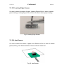
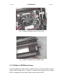
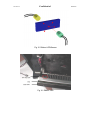
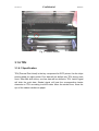
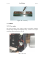
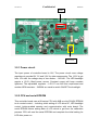
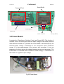
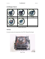
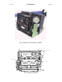
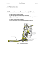
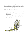
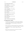
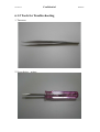
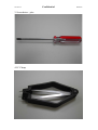
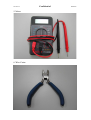
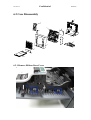
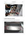
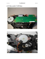
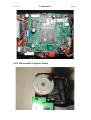
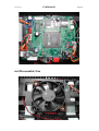
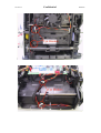
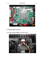
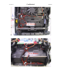
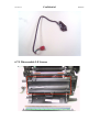
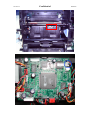
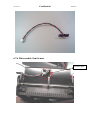
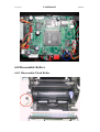
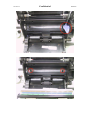
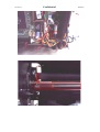
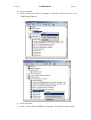
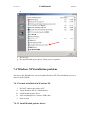
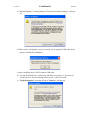
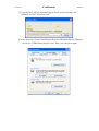
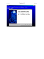
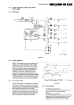
Ver. Ex.1.1 Confidential 630PS Service Guide 2003/7/8 Ver. Ex.1.1 Confidential 2003/7/8 Copyright The information contained in this document is subject to change without notice. Hi-Touch Imaging Technologies makes no warranty of any kind with regard to this material, including, but not limited to, the implied warranties of merchantability and fitness for a particular purpose. Hi-Touch Imaging Technologies shall not be liable for any errors or for incidental or consequential damages in connection with the furnishing, performance, or usage of this material. Reproduction, adaptation, or translation of this manual is prohibited without prior written permission of Hi-Touch Imaging Technologies, except as allowed under the copyright laws. Hi-Touch Imaging Technologies, HiTi, HiTi corporation logo, PhotoDesiree, "Digital mini-lab just for you" and HiTi name (written in Simplified Chinese or Traditional Chinese) are trademarks or registered trademarks in Taiwan, China and other countries of Hi-Touch Imaging Technologies. Disclamer This document is suitable to field site engineers, but not end-user. Field site engineers should read both “Service Guide” and “User’s Manual” to service end-user. Any comments or suggests, please email [email protected]. Ver. Ex.1.1 Confidential 2003/7/8 Chapter 1. Overview “HiTi Photo Printer 630PS” is aimed at the most cost effective standalone photo finish machine for digital camera and photography. With a supreme specification and cost effective design structure, 630PS will surely provide a real photo quality output solution and one-touch photo finish machine for users to print with fun and ease. “HiTi Photo Printer 630PS” is a popular printer with high-speed, high-quality and compact size. This printer is focused on printing “photos”, including of the application on photo (4”x 6”), ID photo (1” or 2”), business card, greeting card and more. “HiTi Photo Printer 630PS” is a standalone printer. You don’t need to communicate with host PC for printing. You can print instantly whenever you want. “HiTi USB Photo Printer 630PS” also supports USB interface to communicate with host PC, which meets the standard of USB 1.1 version. It’s compatible with USB 2.0 host device. Any win32-based photo printing application such as “HiTi PhotoDesiree”, “Adobe PhotoShop”, “Jasc Paint Shop Pro” and “Newsoft Mr. Photo”, or vectors based applications such as “Corel Draw!” are applicable in this printer. “HiTi Photo Printer 630PS” includes of the following functions: 9 Printing Process YMCO 4 passesΰYellow, Magenta, Cyan, and Over-coatingα Over coating ensures that HiTi’s printouts can be kept longer than inkjet printer’s printouts. 9 High Quality Resolution 300x300 dpi Equal to 4800x4800 dpi ΰcompare with inkjet system.α 9 Convenience Dual memory card support. HiTi Photo Printer 630PS provides two types of card slot to let user print instantly. Ver. Ex.1.1 Confidential 2003/7/8 Stand-alone operation & PC link. Could preview what you want to print instantly. 630PS can be your card reader(images only). F/W code and template could be downloaded by USB. Offer large data buffer (32MB SDRAM). HiTi Photo Printer provides an application “PhotoDesiree”, designed especially for printing 4”x6” photos, ID photos, calendars, photo business cards, photo greeting cards and more. Application “PhotoDesiree” extends more functions for photo printer. It makes photo creation easily, and it is very handy to use! Confidential Ver. Ex.1.1 2003/7/8 Chapter 2. Specification No Item Description 1 Model HiTi 630 PS 2 3 Printing Method Color 4 5 Paper Feed Resolution Dye Diffusion Thermal Transfer (D2T2) Continuous-tone output, 256-level each color Cassette type automatic feeder. 300x300dpi 6 Pixel 1200x1800 pixels 7 8 9 10 Printing Size Paper Size Paper Cassette Capacity Ribbon Cassette Capacity 4”x 6” 4”x 7” with detachable boundary 25 sheets 50 images YMCO 11 12 Interface Card Socket 13 14 15 16 17 18 19 File Format Support Power Supply Printer Dimension Controller Dimension LCD Size Image Dimension in LCD Weight USB 1.1 CompactFlash card Type 2 x1 SmartMedia card x1 EXIF, JPEG, DPOF 100~240V, 50/60 Hz,75W 218(W) x 210(H) x 140(L) mm 60(W) x 23(H) x 130(L) mm 1.6” TFT LCD TBD (small footprint) 2.0 kg 20 OS Windows 98/ME/2000 21 Minimum System Requirement Win 98/MEΚ64MB RAM, Pentium PC Win 2000Κ128MB RAM, Pentium PC 22 Package kit 23 Options Power Cord, USB Cable, CD (630 PS Driver, PhotoDesiree, Acrobat Reader 5.0, Mr. Photo 3.1 and Manual), 10 images YMCO Ribbon, 8 images photo paper, 1 image 4 x 4 sticker, 1 image composite (4/2/4) sticker 50 images YMCO Ribbon, 50 images photo kit, 50 images 4 x 4 sticker kit, 50 images composite (4/2/4) sticker kit, 25 images photo and 25 images 4x4 sticker kit, 25 images photo and 25 images 4/2/4 sticker kit, 25 images 4x4 sticker and 25 images 4/2/4 sticker kit Ver. Ex.1.1 Confidential 2003/7/8 Chapter 3. Hardware 630PS Circuit Theory The circuit of 630PS contains five parts: main board, power board, card board, controller board, wires & cables. Functionally, power board is an AC to DC power conversion device, and it provides a 75W, 18V, DC source to drive the 630PS photo printer. Main board adopts 18VDC from power board to drive motor driver ICs and fan, and also transforms the input 18V to 5V and 3.3V by voltage regulators for ASIC, Memory, Video IC, and the I/Os. Card board, which adopts 3.3V DC from main board, provides an interface for main board to control CompactFlash and SmartMedia memory card, it is connected with main board by a 3 pins power wire and a 50 pins signal cable. Controller board, which consists of a 1.6-inch TFT-LCD panel, the user buttons, and the control circuit, is to be the user interface (UI). The 18V DC from power board and the video signals from main board are connected to controller board. Besides, The TFT-LCD panel on controller board is to display images and messages for user operations. Confidential Ver. Ex.1.1 2003/7/8 3.1 Main Board The circuit theory of main board will be divided into seven parts. Controller AD7171 27MHz Capstan Motor Driver 6219 FlashRom Card b/d interface Card b/d power 24MHz Fig 2. Main Board Cam motor Driver ULN2003 34063 ASIC F2680EA Power low detect Ver. Ex.1.1 Confidential 2003/7/8 NAND flash ADF motor Driver 256Mb 3.3V Fig 4. Main Board 3.1.1 ASIC Architecture The most important IC on the main board is FD2680E, which is designed by HITI. This ASIC contains a DSP core, a 8032 MCU, a SDRAM controller, a CCIR601/656 Video controller, a CompactFlash card controller, a SmartMedia card controller, a multi-type thermal print engine, an USB controller, the embedded SRAM, an ADC, and IOs. Firmware can control the action of printer via the versatile interfaces of FD2680E ASIC. 3.1.2 Memory IC a) SDRAM This 256Mbit SDRAM on main board is to be the data buffer. The image file, print data, video frame are temporarily stored during operation. Confidential Ver. Ex.1.1 2003/7/8 b) NOR Flash This 4Mbit flash memory is to stored the MCU code, the DSP code, the logo, the OSD (On-Screen Display) map and etc. c) NAND Flash This 64Mbit NAND flash memory is to stored the template for image processing. 3.1.3 Video Encoder This chip is used to convert the CCIR601/656 digital interface signals to NTSC/PAL video signals. 3.1.4 Memory Card Interface To control the CF and SM memory cards which are inserted on card board via cable. CF socket 50 pin 50 pin Main B/D PCMCIA CF/SM Interface header SM socket 22 pin Power switch 3.3 Volt Confidential Ver. Ex.1.1 2003/7/8 3.1.5 LED & Sensor 3.1.5.1 Status/Error LED Show printer status and error message. Green shining LED means printer is ready. Green blinking LED means printer is busy. Orange blinking LED means error message. (See “Chapter 7. Troubleshooting” for more information about error message.) Fig 6. Status/Error Sensor 3.1.5.2 CAM Sensor Under different status, the position of platen roller is different. Cam sensor indicates the position of platen roller and pinch roller. It has three positions, P1: initial position, P2: load position, and P3: print position. The CAM controls the platen roller moving between these positions, and the CAM sensor detects & feedback the position information to firmware. P1 = Initial Position At this position, the gap between platen roller & TPH is largest. While printer power on or reset, it will be at this position. The large gap between platen roller & TPH enable paper moving through the gap. At this position, the pinch roller is releasing as well. Ver. Ex.1.1 Confidential 2003/7/8 P2 = Load Position At this position, the gap between platen roller & TPH is not as large as P1. But still has gap to enable ribbon scrolling through the gap. The pinch roller touches capstan roller to enable paper loading. P3 = Print Position Platen roller close to TPH, paper unmovable. No gap between platen roller & TPH. Fig 7. Cam Sensor Drawing Fig 8. Cam Sensor Ver. Ex.1.1 Confidential 2003/7/8 3.1.5.3 Leading Edge Sensor It’s used to detect the status of paper. Leading Edge will be on when it detects paper loading; Leading Edge will be off when it doesn’t detect paper loading. Fig 9. Leading Edge Sensor 3.1.5.4 Jam Sensor It’s used to detect the status of paper. Jam Sensor will be on when it detects paper passing; Jam Sensor will be off when it detects paper jam. Fig 10. Jam Sensor Ver. Ex.1.1 Confidential 2003/7/8 Fig 11. Jam Sensor Fig 12. Jam Sensor 3.1.5.5 Ribbon Cassette Sensor It’s used to detect the type of ribbon cassette and the status of ribbon door. Ribbon Cassette Sensor will be on if the type of ribbon cassette is correct; Ribbon Cassette Sensor will be off if the type of ribbon cassette is wrong. In addition, Ribbon Cassette Sensor will be on if it detects ribbon door is closed; Ribbon Cassette Sensor will be off if it detects ribbon door is open. Ver. Ex.1.1 Confidential 2003/7/8 Fig 13. Ribbon Cassette Sensor (Front View) Fig 14. Ribbon Cassette Sensor (Back View) 3.1.5.6 Ribbon LED/Ribbon Sensor It’s used to detect the ribbon status, enable printer to control the ribbon scrolling correct. Detect ribbon color. In yellow or overcoat layer, ribbon sensor senses HIGH. In magenta and cyan layer, ribbon sensor senses LOW. Ver. Ex.1.1 Confidential Fig 15. Ribbon LED/Sensor Fig 16. Ribbon LED 2003/7/8 Ver. Ex.1.1 Confidential 2003/7/8 Fig 17. Ribbon Sensor 3.1.6 TPH 3.1.6.1 Specification TPH(Thermal Print Head) is the key component for D2T2 printer, like the inkjet printing head for inkjet printer. Print data will be shifted into TPH during each clock. After 384 shift clocks, one line data will be shifted to TPH. Latch/ signal will latch the print data. Strobe/ signal will heat the corresponding heater elements on TPH according to shift-in data. More the strobe/ time, more the dye of the ribbon transfers to paper. Ver. Ex.1.1 Confidential Fig 18. TPH Specification Fig 19. TPH (Back View) 2003/7/8 Ver. Ex.1.1 Confidential 2003/7/8 Fig 20. TPH (Front View) 3.1.7 Motor 3.1.7.1 Cam motor Cam motor is a unipolar motor. It’s driven by driver IC “ULN2003”. ULN2003 has high voltage and high current Darlington arrays. Therefore, it can support continuous load of current rating to 500 mA. Fig 21. Cam motor Ver. Ex.1.1 Confidential 2003/7/8 3.1.7.2 Capstan motor Capstan motor is a bipolar motor. It’s driven by driver IC “L6219”. L6219 is designed to operate both windings of bipolar stepping motor. It supports Pulse-Width-Modulation (PWM) control of output current to 750 mA. For PWM control, the maximum output current is determined by user’s selection of a reference voltage and sensing resister. Fig 22. Capstan Motor 3.1.7.3 Ribbon/ADF motor Ribbon/ADF motor is a bipolar motor. It’s driven by driver IC “A3966”. A3966 is designed to operate both windings of bipolar stepping motor. It supports Pulse-Width-Modulation (PWM) control of output current to 650 mA. For PWM control, the maximum output current is determined by user’s selection of a reference voltage and sensing register. Confidential Ver. Ex.1.1 2003/7/8 Fig 23. Ribbon/ADF Motor 3.2 Controller Board The circuit theory of controller board can be divided into four parts. a) Power Circuit b) CPU and serial EPROM c) LCD driver d) LCD and backlight LED 78D05 LCD I/F LCD’s LED fixed Current Control back light control Controller I/F 78D15 LCD control CHIP Serial EEPROM 24C02 78E51 3.3V regulator Ver. Ex.1.1 Confidential 2003/7/8 24MH Tact switch 3.2.1 Power circuit The input power of controller board is 18V. The power circuit uses voltage regulators to provide15V, 5V and 3.3V for other components. The 13.5V is got from 15V after the voltage drop of two diodes – 1N4148 . The LED backlight require a 13.6V--19mA power source. Constant current will keep constant lightness. The adjustable regulator – LD1117 can fulfil this requirement and another NPN transistor – 2N3904 are used to switch ON/OFF the backlight. 3.2.2 CPU and serial EPROM This controller board uses a 80-series CPU with 4KB on-chip FLASH EPROM to do central control -- including initial setting of LCD driver IC, LED backlight control, button-pushed sensing and communication with main board. The serial EPROM stores setting data of LCD which is got from the calibration process. CPU will read the serial EPROM and complete the initial setting for LCD after power on. Ver. Ex.1.1 Confidential 2003/7/8 3.2.3 LCD driver The CM7100 is a video interface IC for TFT color LCD that accept RGB signal inputs on a single chip. It supports a serial data control which can set image quality adjust circuit. 3.2.4 LCD and backlight LED The 1.6-inch TFT LCD panel is used to display images and messages. This panel is driven by a specific LCD driver and its backlight is low DC voltage white-LED. 3.3 Card Board The only one IC on card board is RT9701 -- a power switch. This switch is to disable power supply of memory card sockets when no cards are inserted. After either one of the sockets is inserted a CompactFlash card or a SmartMedia card, the CD(card detection) is pulled low and the power switch will be turned on by ASIC. Fig 24. Card Board Confidential Ver. Ex.1.1 2003/7/8 SmartMedia CompactFlash Card b/d power Card b/d I/F Power control IC EL Cap. (SMD) 3.4 Power Board It contains the Transformer, Snubber Circuit, and Power MOS. The function of Sunbber Circuit is reducing the transient Spike Voltage Power MOS produces when MOS be turned off. It prevents the Power MOS to be destroyed by the transient Spike Voltage. Transformer is the component which transforms energy. It is also separateness of the primary and secondary. It can use proportion of coils to change the voltage between primary and secondary. The Power MOS is controlled with UC3842A to switch energy of Transformer so that is able to regulate Output Voltage. Fig 25 Power Board Confidential Ver. Ex.1.1 2003/7/8 3.5 Power Cord Australia China UK US Europe Fig 26 Power Cord 3.6 Fan It’s used to reduce the temperature of the TPH (Thermal Print Head). Fig 27. Fan Confidential Ver. Ex.1.1 2003/7/8 Chapter 4. Mechanism 4.1 Overview Basic anatomy of 630PL including: A. B. C. D. E. F. G. H. I. J. K. L. Eject Button Case- Back Main Board Card Board Power Board LCD Controller Chassis LCD holder Case- Front Ribbon Door Paper Door Paper Cassette A F G C H B D E I J K L Fig 1. Basic Anatomy of 630PS Ver. Ex.1.1 Confidential 2003/7/8 Fig 2. Chassis and Case-Back of 630PS C A PSTA N M O TO R A D F M O TO R C A M M O TO R Fig 3. Chassis of 630PS Confidential Ver. Ex.1.1 2003/7/8 4.2 Transmission 4.2.1 Transmission of Auto Document Feed (ADF) Device a) Paper Lifter lifts a sheet of paper. b) Paper take-up device loads a paper into printer. c) Paper Path Separation device delivers paper into the space between Pinch Roller and Capstan Roller. d) Capstan Roller presses the paper. e) Other mechanical devices will take following print actions. TPH PLATEN ROLLER CAPSTAN ROLLER PINCH ROLLER PAPER CASSETTE PAPER PATH SEPARATION DEVICE PAPER TAKE-UP DEVICE PAPER LIFT DEVICE Fig 4. Side view of 630PS Confidential Ver. Ex.1.1 2003/7/8 4.2.2 Transmission of ADF Power (See Fig 5) a) When ADF Motor rotates paper lifter, Paper Lifter will start to lift up the plate of paper cassette. The prior paper of the first paper which is placed inside the paper cassette will contact the paper take-up roller and be picked up into the paper path.. b) While the paper passing the leading edge sensor, and going into capstan roller area, capstan roller and pinch roller will press it. Then, capstan and pinch roller will start to move the paper by printer’s command.. ADF MOTOR GEAR 3 GEAR 1 ARM-SWING PAPER TAKE-UP ROLLER GEAR 4 GEAR 2 PAPER LIFT DEVICE SWING GEAR Fig 5. Transmission of ADF Power Confidential Ver. Ex.1.1 2003/7/8 4.2.3 Transmission of Ribbon Take-up Device When capstan roller takes the paper, the ADF motor will release the paper lifter and start to rotate gears and the ribbon. After locating the ribbon to the initial position of each frame, the printing will begin. 4.2.4 Position of Platen, Pinch and Capstan a) When the printer is in normal print status, thermal print head (TPH) will contact Platen Roller tightly. Besides, Pinch Roller will contact capstan roller tightly. b) TPH will not contact platen roller under the process of the paper load and ribbon search. c) For preventing deforming pinch roller, on the standby status, capstan roller and pinch roller have to be separated. For this supporse, the printer built a series of gears and cams to decide the position of Pinch Roller and Platen Roller. TPH PLATEN ROLLER CAPSTAN ROLLER PINCH ROLLER PAPER CASSETTE PAPER PAPER PATH SEPARATION DEVICE PAPER TAKE-UP DEVICE PAPER LIFT DEVICE Fig 9. Position of Platen, Pinch, and Capstan roller Ver. Ex.1.1 Confidential 2003/7/8 Chapter 5. Firmware 5.1 Initialization When the printer is power on, initialization will be as follows. 5.1.1. Initial CAM LED Status = Blinking Green (User will hear a sound of motor cam initializing.) 5.1.2 Ready to Print LED Status = Stable Green 5.2 FW actions Step 1. “Cam Gear” goes to “Load” position Step 2. Load the paper into the printer Ver. Ex.1.1 Confidential 2003/7/8 Step 3. Ribbon registration (Yellow) Step 4. “Cam Gear” goes to “Print” position Step 5. Print Yellow Step 6. “Cam Gear” goes to “Load” position Step 7. Ribbon registration (Magenta) Step 8. Back paper Step 9. “Cam Gear” goes to “Print” position Step 10. Print Magenta Step 11. “Cam Gear” goes to “Load” position Step 12. Ribbon registration (Cyan) Step 13. Back paper Step 14. “Cam Gear” goes to “Print” position Step 15. Print Cyan Step 16. “Cam Gear” goes to “Load” position Step 17. Ribbon registration (Overcoat) Step 18. Back paper Step 19. “Cam Gear” goes to “Print” position Step 20. Print Overcoat Step 21. Eject paper Step 22. “Cam Gear” goes to “Load” position Step 23. “Cam Gear” goes to “Initial” position 5.3 Temperature Control 1. If “Thermistor” detects the temperature is “less than 5 degree Centigrade” or “more less 38 degree Centigrade”, there will be a message pop up to indicate user that the temperature of current surrounding is not suitable to print. Note: It still can print. 2. Firmware will decide to use different heating tables when “Thermistor” detects the surrounding temperature is “less than 18 degree Centigrade”, “more than 30 degree Centigrade” or “between 18 degree Centigrade and 30 degree Centigrade”. 3. Printer will do the warm up action (move Cam gear) if the surrounding temperature is less than 5 degree Centigrade. Ver. Ex.1.1 Confidential 2003/7/8 Chapter 6. Assembly 6.1 Safety Instruction 1. Read these instructions carefully. Save these instructions for future reference. 2. Follow all warnings and instructions marked on the product. 3. Unplug this product from the wall outlet before cleaning. Do not use liquid cleaners or aerosol cleaners. Use a damp cloth for cleaning. 4. Use this product inside. 5. Do not place this product on an unstable cart, stand, or table. The product may fall, causing serious damage to the product. 6. Openings in the cabinet and the bottom are provided for ventilation; to ensure reliable operation of the product and to protect it form overheating, these openings must not be blocked or covered. Placing the product on a bed, sofa, rug, or other similar surface should never block the openings. Theirs products should never be placed near or over a radiator or heat register, or in a built-in installation unless proper ventilation is provided. 7. This product should be operated from the type of power indicated on the marking label. If you are not sure of the type of power available, consult your dealer or local power company. 8. If an extension cord is used with this product, make sure that the total ampere rating of the equipment plugged into the extension cord does not exceed the extension cord ampere rating. Also, make sure that the total rating of all products plugged into the wall outlet does not exceed the fuse rating. Ver. Ex.1.1 Confidential 2003/7/8 Chapter 6. Disassembly 6.1.1 Safety Instruction 9. Read these instructions carefully. Save these instructions for future reference. 10. Follow all warnings and instructions marked on the product. 11. Unplug this product from the wall outlet before cleaning. Do not use liquid cleaners or aerosol cleaners. Use a damp cloth for cleaning. 12. Use this product inside. 13. Do not place this product on an unstable cart, stand, or table. The product may fall, causing serious damage to the product. 14. Openings in the cabinet and the bottom are provided for ventilation; to ensure reliable operation of the product and to protect it form overheating, these openings must not be blocked or covered. Placing the product on a bed, sofa, rug, or other similar surface should never block the openings. Theirs products should never be placed near or over a radiator or heat register, or in a built-in installation unless proper ventilation is provided. 15. This product should be operated from the type of power indicated on the marking label. If you are not sure of the type of power available, consult your dealer or local power company. 16. If an extension cord is used with this product, make sure that the total ampere rating of the equipment plugged into the extension cord does not exceed the extension cord ampere rating. Also, make sure that the total rating of all products plugged into the wall outlet does not exceed the fuse rating. Ver. Ex.1.1 Confidential 6.1.2 Tools for Troubleshooting 1. Tweezers 2. Screwdriver – minus 2003/7/8 Ver. Ex.1.1 3. Screwdriver - plus 4. IC Clamp Confidential 2003/7/8 Ver. Ex.1.1 5. Meter 6. Wire Cutter Confidential 2003/7/8 Ver. Ex.1.1 7. Binder 8. Glue Confidential 2003/7/8 Ver. Ex.1.1 9. HiTi Cleaning Kit Confidential 2003/7/8 Confidential Ver. Ex.1.1 2003/7/8 6.2 Case Disassembly A F G C H B D E I J K L 6.2.1 Remove Ribbon Door Cover Ver. Ex.1.1 Confidential 2003/7/8 6.2.2 Remove Controller 6.2.3 Unplug connector from Case-Back 6.2.4 Loosen screws from Case-Back and then remove Case-Front 6.2.5 Loosen screws from Chassis Ver. Ex.1.1 Confidential 6.2.6 Separate Chassis and Case-Back 6.3 Disassemble Power Board 6.3.1 Loosen screws from the bottom plate of the printer 2003/7/8 Ver. Ex.1.1 6.3.2 Remove Power Board Confidential 2003/7/8 Ver. Ex.1.1 Confidential 2003/7/8 6.4 Disassemble Main Board 6.4.1 Unplug connectors and then loosen screws from Main Board Ver. Ex.1.1 Confidential 6.4.2 Slide Main Board and take it out 2003/7/8 Ver. Ex.1.1 6.4.3 Sockets Confidential 2003/7/8 Ver. Ex.1.1 Confidential 6.5 Disassemble Motors 6.5.1 ADF Motor 6.5.1.1 Loosen screws from Chassis Cut the binder 6.5.1.2 Unplug ADF connector from Main Board 2003/7/8 Ver. Ex.1.1 Confidential 6.5.2 Disassemble CAM Motor 2003/7/8 Ver. Ex.1.1 Confidential 6.5.2 Disassemble Capstan Motor 2003/7/8 Ver. Ex.1.1 6.6 Disassemble Fan Confidential 2003/7/8 Ver. Ex.1.1 Confidential 2003/7/8 Ver. Ex.1.1 Confidential 6.7 Disassemble Sensors 6.7.1 Disassemble Ribbon Cassette Sensor 2003/7/8 Ver. Ex.1.1 Confidential 2003/7/8 Ver. Ex.1.1 Confidential 6.7.2 Disassemble Ribbon LED 2003/7/8 Ver. Ex.1.1 Confidential 2003/7/8 Ver. Ex.1.1 Confidential 2003/7/8 Ver. Ex.1.1 Confidential 6.7.3 Disassemble Ribbon Sensor 2003/7/8 Ver. Ex.1.1 Confidential 2003/7/8 Ver. Ex.1.1 Confidential 2003/7/8 Ver. Ex.1.1 Confidential 2003/7/8 Ver. Ex.1.1 Confidential 6.7.4 Disassemble Cam Sensor 2003/7/8 Ver. Ex.1.1 Confidential 6.7.5 Disassemble LE Sensor 2003/7/8 Ver. Ex.1.1 Confidential 2003/7/8 Ver. Ex.1.1 Confidential 2003/7/8 6.7.6 Disassemble Jam Sensor Remove glue Ver. Ex.1.1 Confidential 6.8 Disassemble Rollers 6.8.1 Disassemble Pinch Roller 2003/7/8 Ver. Ex.1.1 Confidential 2003/7/8 Ver. Ex.1.1 Confidential 2003/7/8 Ver. Ex.1.1 Confidential 2003/7/8 Ver. Ex.1.1 Confidential 6.8.2 Disassemble Capstan Roller 2003/7/8 Ver. Ex.1.1 Confidential 2003/7/8 Ver. Ex.1.1 Confidential 2003/7/8 Ver. Ex.1.1 Confidential 2003/7/8 Confidential Ver. Ex.1.1 2003/7/8 Chapter 7. Problem Verification It is frustrating when things go wrong, but the following pages contain tips that can help you to determine what the problem is and how to fix it. a) Make sure that the connection of cables is secured. b) Check it if your question is similar to those listed below and then follow the instructions found in that section. c) If the problem still exists, or it is not listed, please 9 See FAQ section in HITI website for updated information. 9 Contact us for support. HiTi Headquarters: [email protected] HiTi US branch:[email protected] 7.1 LED blinking You can use LED signal (near the paper slot) to detect what problems happened. LED signal can be divided into stable green, blinking green or blinking orange. Please try to use the following chart to know what problems happened, then search for help. 7.1.1 Green Signal Light It is used to indicate, “printer is processing job”. Signal Reason Description Stable Normal operation Printer is ready for processing job Blinking Normal operation 1. Printer is processing job. 2. Printer is initializing after power on. 7.1.2 Orange Signal Light While sensors detect errors, printer will stop and the orange LED starts to blink. The blinking times indicate different errors. Confidential Ver. Ex.1.1 Error 2003/7/8 Led 630PL 630PS PhotoShuttle 640PS 640DL Transphotable Cover open 1 Ribbon missing 2 Ribbon out 3 Ϥ Ϥ Ϥ Ϥ Ϥ Ϥ Paper out 4 Ϥ Ϥ Ϥ Ϥ Ϥ Ϥ Paper jam 5 Ϥ Ϥ Ϥ Ϥ Ϥ Ϥ Paper mismatch 6 Ϥ Ϥ Ϥ Ϥ Ϥ Ϥ Underrun 7 Ϥ Cam error 8 Ϥ Ϥ Ϥ Ϥ Ϥ Ϥ Sram error 9 Nvram error 9 Sdram error 10 Asic error 11 Ϥ Ϥ Ϥ Ϥ Ϥ Ϥ Adc error 12 Ϥ Ϥ Ϥ Ϥ Ϥ Ϥ Fw checksum error 13 Ϥ Ϥ Ϥ Ϥ Ϥ Ϥ Ϥ Ϥ Ϥ Ϥ Ϥ Ϥ Ϥ Ϥ Card error Ϥ Adf cam error 15 Video error 16 Ϥ Write flash error 16 Ϥ Ϥ Ϥ Ϥ Ϥ Ϥ Ϥ Ϥ Ϥ Ϥ 7.2 Error message of PhotoDesiree7.2.1 If user executes PhotoDesiree to print photo, user's PC has to meet the minimum system requirement. 7.2.2 If user runs Photoshop or other software to print photo, please contact with the vendor of that software for further information. Error message Printer is off-line or paused Allocate memory failed Reason Solving 1. Printer is paused or off-line 2. Printer is not power on. 3. USB disconnected or USB 2. Reconnect USB cable. cable failed. 3. Reinstall driver 1. Please close some applications Windows fail to locate Memory, 1. Please check the status of HiTi Photo Printer. (such this might cause by running too as Word/Excel/PowerPoint), and restart many applications at the same PhotoDesiree. time, or some applications 2. Add memory size Ver. Ex.1.1 Confidential consume huge system resource. 2003/7/8 3. We suggest user to execute "PhotoDesiree" as a single task in windows so as to prevent memory allocation problem. 4. Disconnect the network connection while using printer Create DC failed. Windows fail to locate Memory, 1. Please close some applications (such this might cause by running too as Word/Excel/PowerPoint), and restart many applications at the same PhotoDesiree. time, or some applications 2. Add memory size consume huge system resource. 3. We suggest user to execute "PhotoDesiree" as a single task in windows so as to prevent memory allocation problem. 4. Disconnect the network connection while using printer The Resolution of the Monitor Monitor's resolution setting must Set your monitor's resolution higher than 800 Setting is too Low be over 800x600 at least. X 600. 7.3 Windows 2000 Installation problemIt is very easy to install Kodak printer driver and AP under windows 2000. Follow the instructions on the quick guide; the installation should be very easy. In some cases, user fails at the installation under Win2K. It mainly due to the wrong privilege setting under the system. It must be set as “Administrator privilege” before conducting the installation. 7.3.1 Solving wrong installation under Windows 2000 In some case, user didn’t complete the installation successfully. But part of the driver had been installed into system. Before conducting the re-installation, user needs to clean up previous wrong installations files. Example: Asus CUSL2 (Intel 815e chipset), P3 866, 256M RAM a) Login Windows 2000 as "Administrator". Ver. Ex.1.1 Confidential 2003/7/8 b) Power on printer. c) Check "Control Panel/Device Manager". Uninstall "Unknown device" and "USB Printing Support". d. Power off printer. e. Check "Control Panel/Add/Remove Programs". If old driver exists, remove Ver. Ex.1.1 Confidential 2003/7/8 it. f. Re-boot PC. g. Re-install Kodak printer driver. Then, power on printer. 7.4 Windows XP Installation problem The driver and PhotoDesiree can work under Windows XP. The installation process is same as under Win2K. 7.4.1 Normal installation in Windows XP i. ii. iii. iv. v. Do NOT connect the printer to PC. Login Windows XP as "Administrator". Install Kodak printer driver. After installing driver, connect USB cable. Start to print. 7.4.1.1 Install Kodak printer driver. Ver. Ex.1.1 Confidential 2003/7/8 a) "Digital Signature" warning dialog of "Unknown software package" will pop up. b) Then system will display a screen to notify user to plug the USB cable in the printer to finish the installation. c) After installing driver, NOW connect USB cable. d) "Found New Hardware" will pop up and show a message on "system tray". "Printer device" and "Searching printer driver" will be executed. e) "Digital Signature" warning dialog of "Printers" will pop up. Ver. Ex.1.1 Confidential 2003/7/8 f) "Copying files" will pop up and disappear. Then, no more message like "Finished" or "OK" for user to press. g) Now, check out "Control Panel/System Properties/Hardware/Device Manager", you can see "USB Printing Support" here. Then, you can start to print. . Ver. Ex.1.1 Confidential 2003/7/8 7.5 Install Chipset Software In some cases, user didn’t install the Chipset support software and the PC/Windows can’t recognize USB device. To fix this problem, user needs to install the Chipset software to enable the USB connection. Below is the installation guide for Intel Chipset software: Example: Intel chipset driver a) Due to no "Plug & Play INF" support for Intel (R) chipset components, Kodak recommends user to install chipset software. After installing, please restart PC. b) User can get "Intel chipset software" from the CD that is bundled with Mother Board. User can download the software from Intel's website as well. http://support.intel.com/ Ver. Ex.1.1 Confidential 2003/7/8