1
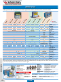
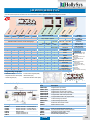
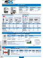
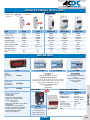
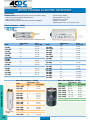
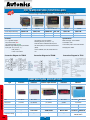
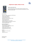
ALARM ANNUNCIATORS Monitors potential free input contacts (NO or NC) 4 to 16, for any change of status (Abnormal) & activates one common output relay for audible device with respective flashing LED windows, thus indicating the “Alarm” status. This flashing annunciation window is “Acknowledged” & “Reset” (when returns back to normal) by external push buttons. • Fully integrated construction. • Powerful Microprocessor Circuit. • NO/NC selectable input configuration. • Optically Isolated input Circuit. • AC/DC auxiliary supply. • Low Power Consumption. • DIN standard panel cutouts. • Two Window Sizes, Big & Small. • Front replaceable windows & Inscriptions. • Built-in system watchdog LED. • Moulded enclosures. • Super Bright LEDs. 14B0S00 416B0S00 10B4SPO 10B6SPO 26B0SPO With Pushbuttons 4 Points 5 Points 6 Points 6 Points 8 Points 12 Points 14 Points 16 Points 22 Points 24 Points Specifications 12B2SPO-* 10B4SPO-* 10B6SPO-* 26B0SPO-* – – 20B14SPO-* – 30B22SPO-* – Cutout Size AL-3030-R AL-3030-Y AL-3030-G Cutout Size – – – – 10B8S00-* – – 20B16S00-* – 30B24S00-* 138x138 210x138 *Add supply Voltage: A: 230VAC, B: 24VDC 24/48V DC / 110/220V AC Potential Free Contacts (NO or NC Site Input: Configurable) 1 NO for Audible Hooter Output: 5A, 230V AC Resistive Rating: Facia Window Size: Big: 60 x 30mm Small: 30 x 30mm Fast: 60 Flash/Min. Slow: 30 Flash/Min. Flash Rate: 20B16S00 Small Window no Pushbuttons 68x138 68x138 68x138 138x138 Aux. Supply: Accessories Code 10B8S00 14B0S00-* – – – 28B0S00-* 312B0S00-* – 416B0S00-* – † 624B0S00-* 68x138 210x138 Interrogation Voltage: 12V DC Response Time: 25m.sec. ±10m.sec Power Consumption: 1.5W/Window Grouping (Trip/Non Trip): Optional Description Cutout Size 138x138 LED: Code 312B0S00 Large Window no Pushbuttons 68x138 Colour Red (Amber/Green on request) ● Red Perspex window 30x30mm c/w LED Block ● Yellow Perspex window 30x30mm c/w LED Block ● Green Perspex window 30x30mm c/w LED Block 28B0S00 † 138x138 210x138 282x138 2x(210x138) Supplied with separate power supply Printing of Front Replaceable Windows Code Description AL-30 AL-60 30 x 30mm transparent film 60 x 30mm transparent film • Black letters on transparent film to be sandwiched between front & rear difusers Description AL-6030-R AL-6030-Y AL-6030-G ● Red Perspex window 60x30mm c/w LED Block ● Yellow Perspex window 60x30mm c/w LED Block ● Green Perspex window 60x30mm c/w LED Block 8 & 10 Channel Alarm Annunciator M4100 Specifications for M1000 • Output relay :Max. 220V AC/2A • Output :Max. 150mA per channel • LED flash frequency :Slow Flashing Light 0.8Hz ±10% Quick Flashing Light 8Hz ±10% • Programming :Switches on rear of unit • Reset/Lamp Test :Via Pushbuttons • Power Consumption :180mA M1000 • Input contact type NO/NC and delays 0-15 secs are selectable individually on all channels. • Two common output relays for siren and alarm with voltage free contacts. • Legend can be typewritten on the label easily accessible behind front plate. • Two integrated push buttons for siren reset/lamp test and alarm accept. • Remote individual selectable blocking with adjustable unblocking delay 0-15 secs. • Plug-in terminal block for easy service. • DC or AC supply voltage. Specifications for M4100 • Consumption: 0.15A • Temp Range: -20˚ to +70˚C • Minimum input delay: 50ms Description Supply Size Code 8-Channel Annunciator 12VDC/AC ±30% 96x96 M4100-12 8-Channel Annunciator 24VDC/AC ±30% 96x96 10-Channel Annunciator 12-24VDC 144x144 Accessories for M4100 Front cover with handle IP54 DPM M0846-00 INSTRUMENTS 12B2SPO M4100-22 M1000-24-00C Front cover with key IP54 M0846-01 177 MICRO PLCs V2 60 -16 -B2 1 V2 30 -13 -B2 1 V1 20 -12 -UN 2 V1 20 -12 -R2 C V1 20 -12 -R1 M9 0-T A2 -CA N M9 0-T 1 M9 0-R 2-C AN M9 0-R 1-C AN M9 0-R 1 M90 extended family of PLCs extends to 158 I/0, GSM and MODbus communication, with embedded graphic operator panel. PLC & HMI programmed with one programme! All models supplied with software, instruction manual, cable & connectors. IP65 when panel mounted Display 240 x 64p Resolution (Pixels) 100 HMI display Keyboard 16 15 24 33 No. of keys Programme 16k words 2048 words 16k words PLC size Real time clock Real-time clock functions (date and time) with 7 year battery backup – all models 1024 256 2048 Coils 1024 256 1600 Registers/integers 256 – 256 32 bit integers 128 (32 bit) 64 192 Timers 64 (32 bit unsigned) – 64 (32 bit unsigned) Double word 0.8µsec 12µsec 0.8µsec Execution time Communication 2 ports 1 port 2 ports RS232 1 port RS232/485 converter supplied 1 port RS485 – 1 port – – 1 port 1 port – 1 port CANbus Master/slave protocol – Master/slave protocol MODBUS Up to 8 phone numbers Up to 6 phone numbers, up to 1k of user defined messages Up to 8 phone numbers GSM I/Os 7 pnp/npn 8 pnp/npn 8 pnp 10 pnp 16 pnp/npn Digital inputs 3 (32 bit) 2 (32 bit) 2 (16 bit) 2 (32 bit) High speed input 12 12 33 24 – 25 2 2 (2 below) Analog input 26 – – Thermocouple/PT100 6 – 10 6 – Relay outputs – 11 8 4 pnp/npn – 10 pnp outputs – 1 (0-10V) – – Analog outputs – 1 (1.5kHz) – 2 (50kHz) npn – 2 (2kHz) Highspeed output Up to 64 extra I/O via 8 expanders I/O expansion Up to 128 I/O extra via 8 expanders General 24VDC 12/24VDC 12/24VDC Power supply 96 x 96 218 x 184 260 x 184 Size mm 96 x 96 Notes: 1) High speed counter/shaft encoder/frequency measurer of normal digital inputs, 10kHz max. Can be used as normal digital input. 2)10 bit analog input: 0-5V, 0-10V, 0-20mA, 4-20mA. 3) 10 bit analog input: 0-10V, 0-1mA, 4-20mA,4-20mA. 4) 10 bit analog input: 0-5V, 0-10V. 5) 10 bit analog input: 0-10V. 6) 14 bit universal input for thermocouple, PT100, 0-10V, 0-20mA, 4-20mA. 8 lines x 22 characters 128 x 64p 255 1 line x 16 characters 80 INSTRUMENTS Communication Options Expansion Modules • RS232/485 Up to 64 mixed M90 family units • CANbus • MODBUS • GSM/SMS control • Remote access with any phone-line modem Note: when using expansion modules expansion adaptor must be installed One Windows-based program for both PLC & HMI 178 DPM 128 x 64p EX-A1 IO-DI8-TO8 IO-AI4-AO2 IO-DI8-RO4 IO-DI16 IO-TO16 IO-RO8 EX90-DI18-RO8 IO-PT4 Accessories OPLC-GSM-K1 M90-19-R4 V200-19-ET1 Expansion Adaptor 8 Digital Inputs, 8 Transistor Outputs 4 Analog Inputs, 2 Analog Outputs 8 Digital Inputs, 4 Relay Outputs 16 Digital Inputs 16 Transistor Outputs 8 Relay Outputs 8 Digital Inputs, 8 Relay Outputs 4 PT100 Inputs, -42 to 112°C GSM modem, magnet antenna, cables and adaptors RS232 to RS422/485 converter Ethernet module for PLC V230 & V260 only For power supplies, see page 69. LM MICRO SERIES PLCs 24VDC 240VAC 24VDC 240VAC 125(L) x 90(W) x 70(H)mm 1 – Yes Yes 1 – Yes Yes 5 3 – – 6 – 1 Point, 20kHz 2 5 3 – 6 – – – 2 1 – Yes Yes 11 3 – – 10 – 2 Points, 20kHz 4 Programming Languages 9 3 2 8 – 1 – 4 21 3 – 16 1 – – 7 HT 68 00 T 50(L) x 90(W) x 70(H)mm Power Supply Size 12 bit A/D 10 000 000 Open/ Close <10ms <10ms <10ms 320 x 240 640 x 480 10 000hrs 200mHz RISC Resolution Timers/ Lifespan Excecution time Real Time Clock PLC Program Size 1 1 Yes Yes General HMI Display 21-28VDC 192 x 138mm 224 x 161mm 1 – Yes Yes HT 66 00 C LM 33 30 -E AM DM R LM 32 31 -E Expansion Modules 240VAC Unlimited number of counters, 15 bits counting range Unlimited number of timers, 1ms to 49days 0.37µs per instruction Real time clock function, 10 years back-up 60 000 words 65 535 words – – – – – – – – – – – – 4 – – – 4 – – – 4 – – 4 – – – – – – 4 – – – – – Programme 128k Words Communication RS232 RS485 Modbus G-Mode I/Os Digital Inputs Digital High Speed Inputs Analog Input Relay Outputs PNP Outputs Analog Output Pulse Output Max Expansion Module Connections 1 2 3 4 A B C D E F Connection to expansion modules Wiring terminal for output + input power supply Wiring terminal for input + output power supply RS-232/RS-485 communication port RUN/STOP operation switch + analogue presets I/O channels status indicator PLC status indicator - Run, Stop, Com, Error Heat radiator DIN Rail fastener Hole for backplane or wall mounting • Instruction List (IL) • Function Block Diagram (FBD) • Sequence Function Chart (SFC) • Structual Text (ST) • Ladder Diagram (LD) • Continuous Function Chart (CFC) Communication Options Catalogues & Manuals LD3000 LD3001 LD3002 HT6101 LM3101 HMI101 LM Micro Series PLC - Hardware Manual LM Micro Series PLC - Software Manual LM Micro Series PLC - Instruction Manual HMI User Guide Complete software & info Complete software & info Expansion Modules Code LM3210-EDI LM3211-EDIA LM3220-EDOT LM3222-EDOR LM3221-EDOT LM3223-EDOR LM3310-EAI LM3320-EAO LM3401 LM3403 8 Digital 24VDC input module 8 Digital 230VAC input module 8 Digital 24VDC solid state output module 8 Digital 230VAC /24VDC relay output module 16 Digital 24VDC solid state output module 16 Digital 230VAC/24VDC relay output module 4 Channel Analog input module 4 Channel Analog output module Profibus DP slave interface module Ethernet interface module LS3601 LA3801-COM-300 LA3810 HT6100 HD2100 LM PLC & HMI Programming Software CD LM Communication Cable - RS-232 Cable (2m) LM Expansion Module (500mm length) HMI USB Programming cable RS-232 Serial programming cable Accessories DPM Description INSTRUMENTS LM 32 30 -E LM 31 09 CPU Modules LM 31 07 E LM 31 06 LM 31 05 LM 31 04 DM T The Lm Micro Series PLC is comprised of various modules. The basic functional configuration requires a CPU module working as a basic unit, in complement with optional expansion modules such as communication modules, digital I/0 modules and analogue I/0 modules 179 kWh METERS Rotating Disc kWh Meters 0142 Authorisation No. 0102402 1-Phase 230V HX12D-40 HX12D-60 HX12D-80 Mechanical Counter kWh Meters DDS223-30 DDS223-63 1-Phase 230V Range Digital kWh Meters DDS722-100 Range 3-Phase 380V+N 10-40A HX34D-80 20-80A 15-60A HX34D-100 30-100A 20-80A HX34C CT-5A Size (mm): 160H x 122W x 126D Size (mm): 260H x 170W x 135D 6 Digit register Metal Base and Polycarbonate cover Lower bearing is magnetic suspension type HX34 HX12D-40/60 Range Size DDS223-30 5-30A 1m 5-63A 2m DDS223-63 5-100A 3m DDS722-100 3-Phase 400V+N Range Size DTS722-60 5-60A 6m 3-Phase 400V+N Range 5-100ASize Pulse/kW 6m DTS722-100 DTS722-60/100 DDSF223-30 DDSF223-63 DDSF722-60 Pulse/kW 1-Phase 230V DDSF223-30 DDSF223-63 DDSF722-60 3-Phase 400V + N 2000 2000 800 Pulse/kW 1m=17.5mm Wide • Pulsed output 3200 Imp/kWh • Class 1 320 160 DSS722-5 DSS722-60 DSS722-100 DSS722-5/ 60/ 100 Range Size Pulse/kW 5-30A 5-63A 5-60A 1m 2m 3m 2000 2000 1600 Range Size Pulse/kW 1.5-5A (CT) 5-60A 5-100A 6m 1600 6m 320 6m 160 PRE-PAYMENT kWh METERS Pre-payment kWh Meters Code Description Amps Output Pulses/kW DDSY238-60 Single Phase DTSY238-60 3-Phase 15-60A 15-60A 200 DTSY238-80 3-Phase meter. 20-80A 100 4 wire 400V+N 4wire 400V+N 1600 Accessories Code DDSY-C DDSY-P Description Pre-payment Card Card readers. c/w program software DDSY-C INSTRUMENTS • Power failure memory • Direction of power indication • Anti-theft function • Coded card for fraud protection • Software requires Windows XP© or Windows 7© DDSY-P POWER FACTOR METER Digital Power Factor Meter Code ECR-3-72 ECR-3-96 Size 72 x 72 96 x 96 Operating Voltage 230VAC ±10% 230VAC ±10% Non-flammable enclosure Flush mounting with rear terminals 180 DPM Accuracy CT-Ratio Range Display 1% ±1 digit 1% ±1 digit .../5A .../5A 0.00-0.99 0.00-0.99 4-digit 14.2mm high 4-digit 14.2mm high MODULAR ENERGY METER (kWh) c/w tamper-proof terminal seal • DIN Rail Mount • Operating Temp: -20 to 50°C Code Supply Voltage Un Current, (I max) Operating Current Frequency Operating Voltage Power Consumption Precision accuracy class Pulse transmission Recorded harmonics Size: 1M = (17.5mm) Digits c/w 80A CT ES-32L ES-80L CONTAX 2511 CONTAX 3221 CONTAX 6521 230VAC 5 (32)A 0.02-32A 50/60Hz 230VAC <2VA Class1 1000lmp/ kwh – 1m 6+1 230VAC 40 (80)A 0.08-80A 50/60Hz 230VAC <2VA Class1 1000lmp/ kwh – 1m 6+1 230VAC 5(25)A 0.02 to 25A 50/60Hz 195 to 253V 0.5VA Class 1 Type SO Until 7kHz 1m 5+1 230VAC 5(32)A 0.02 to 32A 50/60Hz 195 to 253V 0.5VA Class 1 Type SO Until 7kHz 2m 5+1 230VAC 10(63)A 0.04 to 65A 50/60Hz 195 to 253V 0.5VA Class 1 Type SO Until 7kHz 2m 5+1 kWh METERS W, Wh or VA, Vah or VAR, VARh or PF ELF3234 W, Wh, PF or VA, Vah,PF or VAR, VARh, PF ELF3234-3 V, A, F ELF3259 • Inputs (V), 110 or 400VAC Range: 80-500V 3 Phase 4 Wire • Input (I) 1A or 5A programmable • Supply Volts: 80-270VAC @ 3VA Accuracy: 2% for VARh All others: 1% • Phase wise & total RMS for power, total for Energy Meters • 10 year back-up of integrated data • VA function selectable 3D or Arithmetic • V shows all Line-Line, Line-Neutral, Individual & Average Voltages • Size: 96 x 48 x 40(D)mm 1 x kWh 1C15WP 2 x kWh 1C15WP2 3 Phase 400V + N kWh Meter C/T Ratio selectable by DIP Switch Selectable Primary CT Current: 5, 10, 15, 20, 25, 30, 40, 50, 60, 75, 80, 100, 120, 150, 200, 250, 300, 400, 500, 600, 750, 800, 1000, 1200, 1250, 1500, 1600, 2000, 2500, 3000, 4000, 5000, 6000 1C15WRP kWh and kVARh 3 Phase 400V + N Indication (Active and Reactive Power) • 7 Digit Electro-mechanical display • Accuracy: 2% (kWh) 3% (kVARh) • 7 Digit Electro-mechanical display • Accuracy: 2% • Pulsed Output kWh Indicator Digital Power kWh Meter Code Supply Voltage Un Current, (I max) Operating Current PM-KW1 0-99kW Indicator • c/w 16A Plug & Socket • Ideal to check your kW usage from generator etc. DPM Frequency Operating Voltage Power Consumption Size: 1M = (17.5mm) Digits RIMD.W15 230VAC CT.../5A 60, 100, 150, 250, 400, 600, 1000/5A 50/60Hz 195 to 253V 4VA 2m 3 INSTRUMENTS Code 181 kWh METERS Zaptronix kWh Meters Features: • Billing meter for active (kWh) import & export energy • 3 Phase , CT and VT connected Meter • Low cost, no maintenance required • Large , Multi function LC -Display • Easy Meter Communication via Infrared flag port • Engineering software included/ available for download at no charge ZAP1CS ZAP1CS-R Code Type Mounting System V Range Amps Accuracy Single Phase High Load (100A) Direct Connect, Class 1 Accuracy Billing Meter ZAP1CS 1ph, 2-wire, 230V 184-275V 1ph, 2-wire, 230V with BS Din Rail 184-275V ZAP1CS-R RS485 Serial Port • Remote automated meter reading ready (ZAP1CS-R) BS DIN Rail Three Phase Active Energy Meter (CT-Connected) ZAP03DS* ZAP03BS* DIN BS DIN Rail Base Mount 3Ph, 4 wire, 230/400 3Ph, 4 wire, 230/400 *Add 110V for 3 phase system 3PH, 3 Wire, 88-132V (P-P) 100A 10-100, Class 1 100A 10-100, Class 1 184-275V (L-N) 5A 184-275V (L-N) 5A 1-5/6, Class 1 1-5/6, Class 1 kWh Meter + Maximum Demand ZAP03BE-MD* BS 1-5/6, Class 1 Base Mount 3ph, 4-wire, 230/400V 184-275V (L-N) 5A *Add 110V for 3 phase system 3PH, 3 Wire, 88-132V (P-P) Energy & Maximum Demand ZAP03BE-MD only Features: • kWh, kVAh, kVArh • Data & Event logging Measurement parameters • kW and kVA • RS232 • Watt, VAr, VA (Import/Export & per phase) • Block & Moving window • Pulse output • Volt, Amp, Power Factor, Frequency • Time of use ZAP03DS kWh Meter + Maximum Demand + Load Management (Load Shedding) ZAP03LM Features: ZAP03BS / ZAP03BE-MD / ZAP03LM ZAP3AM BS Base Mount 3ph, 4-wire, 230/400V (L-N) 5A 1-5/6, Class 1 As per ZAP03BE-MD plus: I/O; 2 x I/P MD synch, E01, water or gas pulse (programmable); 4 x O/P load shedding, rated for 20mA @ 30VDC. Additional Registers: • Target demand • Interlock timer • Load priority setting • Percentage Hysteresis • Override • Load switching frequency PI-Range Profiling - Energy Demand Logging Multi-tariff Meter - IEC 62053-21 ZAP3AM5/P ZAP3AM100 ZAP3AM160 Features: – – – Base Mount Base Mount Base Mount 3Ph, 4 wire, 230/400 3Ph, 4 wire, 230/400 3Ph, 4 wire, 230/400 230V/400V 230V/400V 230V/400V 5A 100A 160A 1-5/6, Class 1 10-100, Class 1 10-160, Class 1 • Billing meter for active (Wh) and reactive (VArh) energy demand (VA) • Remote automated meter reading ready with ZAP-EDAT • Flexible multi-tariff (TOU) billing meter with auto registration • Profile logging of total energy and average energy demand Lambda-Range Logging - Energy Demand Logging Multi-tariff Meter - IEC 62053-21 ZAP3AM5 230V – ZAP3AM5 110V – Features: INSTRUMENTS ZAP-OPTO 182 3Ph, 4 wire, 230/400 230V/400V 3Ph, 3 wire, 110V (P-P) 110V-480V 5A 5A 1-5/6, Class 1 1-5/6, Class 1 • 4 Quadrant, billing meter for active (Wh) and reactive (VArh) energy demand (VA) • Data storage of last 16 months energy and maximum demand for 4 tariffs • Load profile with integration period 1, 5, 30, 60min • Event registration of power outages, per phase voltage loss, under/ over voltage • Full multi-tariff (TOU) billing meter with auto registration • Extensive 6 channel logging from 32 readings and event recording • Remote automated meter data acquisition via IP or GSM-GPRS/SMS Accessories ZAP-EDAT ZAP-SOFT *Note: All 3-phase meters must be programmed before use Base Mount Base Mount ZAP-OPTO ZAP-OPTO/USB *ZAP-PRO ZAP-MPS • EDAT+g for GSM-GPRS AMR at multi meter (up to 128) Installations ZAP3AM, ZAPICS, ZAP03LM • EDAT+e for Internet AMR at multi meter (up to 128) installations ZAP1CS, ZAP3AM Remlt! Lite Programming Software CD. – download for free. Can be downloaded from www.zaptronix.co.za/downloads, This is for ZAP03DS , ZAP03BE, ZAP03BS Optocoupler RS232 for BS type housing Optocoupler USB for BS type housing Factory programming for ZAP kWh meters (free service) (MPS) Meter reading & configuration software. Free download from www.zaptronix.co.za This is for ZAP03AM, ZAP1CS DPM ly end ri Eco -F ENERGY SAVING CONTROLLER Geyser Controller with Embedded Microprocessor Geysers are the largest user of electricity in most households using up to 60%. GC-100 geyser controller will save 40%-60% of geyser usage. Code Features GC-100 • Immediate saving from first monthly bill. • Ensures geyser is off during peak periods • Back-up battery to retain memory • Override switch geyser off and on • 8 Pre-programmable time periods Technical Info • Input Voltage: 220/ 240VAC 50Hz • Mounting: Din Rail • Memory: 120 day battery • Current Sensor: 20Amps • Relay output 20A Passive Power Factor Correction Power Factor Correction (PFC) is a technique of counteracting the undesirable effects of electric loads that create a power factor less than one. This range of passive (PFC) units can save 10%-20% of energy consumpion. Code MS15 ES100 Description Dimensions Single Phase (2000kwh) 125 x 85 x 60 Three-Phase (10 000Kwh) 240 x 190 x 90D ES15 ES100 ES300 ES3001 ES3002 Single-Phase (1000kwh) 16A SA plug-in type Features Prolongs life of appliances Stabilise electrical current Available in single and three-phase Suitable for home, shops, offices, restaurants, etc. Three-Phase (6200Kwh) 190 x 140 x 70D Three-Phase (15 000Kwh) ES300 95 x 56 x 56 Combination units consist of both geyser controller and passive power factor (energy saving). These are parallel connection types, for single and three phase units, some available fitted with surge protection. ES100-GC ES100-GC-SS ES100-2GC-SS ES300-GC ES300-GC-SS ES300-2GC-SS Single-Phase voltage: 220-240VAC 50Hz Three-Phase voltage: 380-420VAC Operating temperature: 60˚C (max.) The three-phase energy saver can be wired either at the DB or the incoming Eskom box. Note: As long as the black is connected to neutral, it does not matter which of the other wires connect to which phase. 240 x 190 x 90D Combination Geyser/ Power Factor Protection & Surge Protection Code Technical Info Description Dimensions Single phase power + Geyser + Surge protection 170 x 200 x 85mm Single phase power + Geyser controller 170 x 200 x 85mm Single phase power + 2 x Geyser + Surge protection 170 x 200 x 85mm Three phase power + Geyser controller 210 x 215 x 100mm Three phase power + Geyser + Surge protection (3ph+N) 210 x 215 x 100mm Three phase power + 2 x Geyser + Surge protection (3ph+N) 210 x 215 x 100mm Technical Info Single-Phase voltage: 220-240VAC 50Hz Three-Phase voltage: 380-420VAC Surge Protection: 65kA Red (or Brown) Wire to Red Phase White (or green/ Yellow) Wire to Phase Blue wire to Blue phase Black Wire to Neutral White (or Brown) wire to Seconary side of Geyser C/B (or Isolator) Red Wire to Geyser Ditto for other controllers Monitor your own electricity and save power and money! (1-Phase) Monitoring System Code AML-1208 Kit Description • 1 x Current sensor • 1 x Sender unit • 1 x Display unit (3 Phase) Monitoring System • 4 x Batteries • 1 x User Manual • 1 x Desk Stand *Add 2 x Current Sensor (AML-CS) + AML-1208 Code AML-CS Description Current Sensor With the standard electricity In-Home-Display unit, you can clip the current sensor around the electricity meter's live feed supply such that it measures the total electrical power entering your home or office. Power consumption will be recorded and transmitted to the display unit wirelessly. The following features are provided also: • Dual battery system is used to extend operation period and to prevent data lost during battery changing • Indicate existing cost alert level by Tri-color LED • Display temperature and current time • Clock alarm and cost alert level setting • Monitor up to 8 sensors • Support >30m RF transmission This product is a semi-portable communication product used in the household market. You can view the instant electricity consumption, cost-up-to-current-hour and records (eg. hourly, daily, weekly, and monthly) as well as estimated CO emission produced. ² Transmitting frequency 433mHz with proprietary communication coding for different market segments. DPM INSTRUMENTS WIRELESS POWER DISPLAY UNIT 183 GENSET CONTROLLERS Code Application Relay outputs Digital inputs DSE501K-1 Manual Start/Stop Fuel and Start solenoid Common Alarm Low oil Pressure High Engine Temp. Auxiliary Shutdown Charge Fail Analog inputs None Config. Method None Event logging *Comms. Port RS232 or RS485 None None Operator Display First Up Fault *Low oil Pressure *High Engine Temp. *Charge fail warning *Auxiliary shutdown Other Feautres Panel Cutout CANbus 68 x 68 None 704 AMF Fuel on, Crank 2 x Configurable 4120 DSE720 AMF Fuel, Crank, Mains & Alt Contactor 2 x Configurable Low oil Pressure High Engine Temp. Auxiliary Shutdown +2 Configurable None AMF AMF Fuel, Crank, Mains & Standard Gen Controller Alt Contactor Outputs 2 x Configurable + 4 x fully Configurable Low oil Pressure Low Oil Pressure, High Engine Temp, Standard Gen Controller High Engine Temp. Emergency Stop, Remote Start (3 Inputs Auxiliary Shutdown attempt) or Mains Stimulation, + 8 fully Configurable +2 Configurable Charge Fail (D+) 2 Configurable None 2 Inputs. Coolant temp. & oil 4 including pressure, pressure with the option of temperature and fuel volume configuring these as digital inputs Via front face Via front face Front face or PC via interface Limited front face, Fully via type P810 USB programming port None None None 250 most recent events None None None Type of events recorded can be selected. Fitted with both RS232 and RS485, but only one can be used at a time Warning/Shutdown & Hour counter + warning/ Backlit LCD scrolling Mains Multi Menu Access via front active inputs are shutdown & active Alternator voltage. Load Current, panel: Status, Engine, signalled by LEDs, inputs are signalled by Oil Pressure, Engine Temperature, Generator, Mains, Alarms, load transfer (contactor LED's Load transfer, DC Volts, Hours Run, RPM and Event log, Serial Port control) have a mimic (contactor control) have Hz, Alternator or Mains info, LED display a mimic LED display Common Alarm and Scroll Button. Mimic LEDs, Mode Selection • Modbus RTU • IP65 gasket • USB connectivity & SCADA • Engine exercise Schedular • Dummy load control plus load shedding up to 5 stages 149 x 109 154 x 98 182 x 137 220 x 160 None None None CANbus Code All controllers are suitable for 12 or 24V DC systems. *For remote real time diagnostics and telemetry, including SMS communications. PSTN or GSM modem not included. ROTARY ENCODER 40mmØ, Shaft type encoder Coupling Code Code Code INSTRUMENTS Type (Incremental Type) P810 INTERFACE USB Interface Module c/w cables and software for programming Model 720 50mmØ, Shaft type encoder (Incremental Type) E4DC-6/6 E5DC-8/8 E5DC-10/10 Code E40S6-*-3-1 E40S6-*-3-2 E40S6-*-6-L Totem Pole Output (HTL) NPN N/O Output (TTL) Line Driver Output (TTL) Pulses/Revolution Supply Volts 12-24VDC 12-24VDC 5VDC *Add to code: *100, 360, 500, 1000,1024 Specifications Shaft Totem Pole Output NPN Open Output Line Driver Output Max. Response Freq. 184 DSE7320 Code E50S8-*-3-1 E50S8-*-3-2 E50S8-*-6-L 12-24VDC 12-24VDC 5VDC *Add to code: *50, 100, 200, 250, 360, 1000, 1024, 1800, 2500, 3600 6mm 8mm Low Load current: Max. 30mA, Residual voltage: Max. 0.4V High Load current: Max. 10mA, Output Voltage: Min. 1.5V Load Voltage: Max. 30V, Load current: Max. 30mA, Residual Voltage: Max. 0.4V Low Load current: Max. 20mA, Residual Voltage: Max. 0.5V High Load current: Max. -20mA, Output Voltage: Min. 2.5V 180kHz DPM Supply Volts GENSET CONTROLLERS 8-32 VDC EAOM-9 EAOM-9F Model Size (mm) Automatic engine start/stop and load transfer Manual, Automatic and Test Mode control User configurable inputs User configurable outputs Optional expansion board with user configurable 8 I/O EXOM-210.FL.EXR Speed sensing from alternator voltage Speed sensing from magnetic pickup 3 resistive sender inputs (oil, fuel, temp.) Load current measurement Generator Volts measurement Mains Volts measurement Earth current measurement Exercise at programmed time intervals RS-232, Modbus ASCII Serial communication Available for Remote using by PC software Standard modem communication Generator Power measuring by kVA, kW, kVAh, kWh, kVAr, kWrh Event logs Display Mains contactor outputs Generator contactor outputs Programmable weekly working permit calendar Maintenance warning (working hour or elapsed month) Fully Programmable Simple push button controlled operation Model Automatic engine Start/Stop Automatic Shutdown on fault condition Alternator voltage and frequency measurement Load current measurement Remote Start/Stop input 3 resistive sender units User configurable inputs User configurable outputs Speed sensing off Alternator Speed sensing off magnetic Pickup RS-232 Serial Comms Remote use from PC Standard Modem Comms Display Size (mm) EAOM-36 Y EAOM-210FLS EAOM-2FDS EAOM-09F MESSENGER with GSM EAOM -210FLS EAOM-210FDS MESSENGER EAOM-19 EAOM-09 N N N Y N N Y N N N L1/N L-L-N N N N N N Y Y N N L1/N L-L-N N N Y Y Y Y Y N N L1/N L-L-N N N Y Y Y Y Y Y Y L-L-N L-L-N Y Y Y Y Y Y Y Y Y L-L-N L-L-N Y Y Y Y Y Y Y Y Y L-L-N L-L-N Y Y Y Y Y N N N Y Y Y N LED Y Y N N Y Y N LED Y Y N N Y Y N LED Y Y N N Y Y 96 x 96 Y Y 2 1 72 x 72 Y Y 2 N EAOM-7 Y 144 x 204 x 37 144 x 204 x 37 144 x 204 x 37 144 x 204 x 37 Y Y Y Y Y Y Y Y 6 6 2 6 4 4 1 4 EAOM-71 Y Last 50 events Last 32 events LED LCD Y Y Y Y Y Y Y Y Y Y Y Y Automatic Transfer Switch ATS-10 Controls Generator remote start Y Load transfer to mains Generator Voltage/ Mains and generator Power Measurement contactor 1 Phase Monitors Y 3 Phase mains voltage Y 3 Alternator voltage 2 Program parameters Y Y Y Frequency Measurement N Y N 2 1 Y Generator Voltage/ Power Measurement 3 Phase Y N 3 2 Y N Y Y Y Y N LED 72 x 72 Y Y Y LED 96 x 96 Y Y Y LED 96 x 96 DPM Size: 72 x 72mm Last 32 events LCD Y Y Y Y Y Y Manual Key Start Controller EAOM-3 Controls Fuel and stop solenoid Starter motor Manual generator start/ stop Preheat (Glow Plug) Monitors Engine running time Error Indication Fail Monitoring Low oil pressure High temperature Over speed failure Charging fail INSTRUMENTS EAOM-19 Size: 72 x 72mm 185 Specifications MOTOR STARTING & LIGHTING CAPACITORS • Dielectric material: Metalised polypropylene, low losses non inductive winding. • Case and cover: self-extinguishing thermoplastic resin. • Lead: 2 x 0.75mm2. PVC 90°C. • Reference standards: CEI 33-3; VDE 560-8; ASE 1029; VDE EN60252. • Climatic category: 25/85/21. • Standard tolerance: ±5%; -2+8%. • Rated frequency: 50 – 60Hz. • Voltage: 1.1 Un at 50Hz. • Dissipation factor at 20°C, V = Un, 50Hz: ≤15:10-4 Lighting Capacitors – 250VAC Supplied with 150mm flying leads and M8 mounting stud Code CA-2MF CA-2.5MF CA-3MF CA-3.5MF CA-4MF CA-4.5MF CA-5MF CA-6MF CA-6.3MF CA-7MF CA-7.5MF CA-8MF CA-9MF CA-10MF CA-11MF CA-12MF Capacitance (µF) Size Ø x H mm 2 25 x 53 3 25 x 53 2.5 Code CA-13MF CA-13.5MF CA-14MF CA-15MF CA-16MF CA-17.5MF CA-18MF CA-20MF CA-25MF CA-30MF CA-32MF CA-35MF CA-40MF CA-45MF CA-50MF CA-55MF CA-60MF 25 x 53 3.5 25 x 53 4 25 x 53 4.5 25 x 53 5 25 x 69 6 25 x 69 6.3 25 x 69 7 25 x 69 7.5 30 x 73 8 30 x 73 9 30 x 73 10 30 x 73 11 30 x 73 12 35 x 73 CAPACITORS & PFC Motor Run Capacitors – 480VAC Capacitance Size Code (µF) Ø x H mm With mounting stud M8 186 CAR-1.5MF CAR-2MF CAR-3MF CAR-4MF CAR-5MF CAR-6MF CAR-8MF CAR-10MF CAR-12MF CAR-14MF CAR-16MF CAR-18MF CAR-20MF CAR-25MF CAR-30MF CAR-40MF CAR-50MF 1.5 2 3 4 5 6 8 10 12 14 16 18 20 25 30 40 50 Capacitance (µF) Size Ø x H mm 13 13.5 14 15 16 17.5 18 20 25 30 32 35 40 45 50 55 60 35 x 73 35 x 73 35 x 73 35 x 73 35 x 73 35 x 73 35 x 73 35 x 96 35 x 96 40 x 95 40 x 95 40 x 95 50 x 100 50 x 100 50 x 100 50 x 100 50 x 100 Motor Start Capacitors – 275VAC Capacitance Size Code Ø x H mm (µF) CAS-30MF CAS-50MF CAS-100MF CAS-125MF CAS-130MF CAS-160MF CAS-300MF CAS-328MF 25 x 55 25 x 55 30 x 63 32 x 73 32 x 73 32 x 73 32 x 73 32 x 73 35 x 75 35 x 75 35 x 75 35 x 98 35 x 98 35 x 98 40 x 94 50 x 100 50 x 100 T 30 - 36 50 x 85 88 - 106 50 x 85 53 - 64 124 - 149 130 - 156 145 - 174 270 - 324 328 - 454 50 x 85 50 x 85 50 x 85 50 x 85 50 x 110 60 x 110 warning: all PFC systems require protection against harmonics, generated by such devices as variable speed drives and UPS’s, and transient surges including lightning. POWER FACTOR CORRECTION CAPACITORS Capacitance tolerance: -5 +10% Frequency: 50Hz (60Hz on request) Temperature Range: -40°c + 55°c Dielectric Losses: ≤ 0.5 W/kVAr Maximum over voltage: 1.11 x Un Maximum over current: 1.5 x In Fuse ratings to be 1.5 to 1.8 times the nominal capacitor current Ideal for use with harmonic filters • Terminals – clamp type • Mounting via stud • Overpressure disconnection • Discharge resistors fitted Manufactured to EN60831-1/2 • Maximum THD in Voltage: • Maximum THD in Current: • Discharge Resistance: • Dielectric: • Voltage test between terminals: • Voltage test terminals to case: • Standard EN60831-1/2 Cylindrical 3 phase power factor capacitors Rated Current Wire kVAr at Voltage per Phase Size 440V 400V 440V 440V 440V 440V 440V 440V 440V 440V 440V 440V 440V 440V 440V 440V 440V 440V 440V Rated Voltage 550V 550V 550V 550V 550V 550V 550V 550V 550V 550V 1 1.5 2 2.5 3 4 5 7.5 10 12.5 15 20 25 30 35 40 50 440V 440V 440V 440V 440V 440V 440V 440V 440V 440V 440V 440V 440V 440V 440V Manufactured to EN60831-1/2 5 7.5 10 12.5 15 20 25 30 35 40 45 50 60 70 80 ØxH mm Code 1.3A 1.9A 2.5A 3.2A 3.8A 5.0A 6.3A 9.7A 13A 17A 20A 26A 33A 39A 46A 58A 66A 2.5mm2 2.5mm2 2.5mm2 2.5mm2 2.5mm2 2.5mm2 6mm2 6mm2 6mm2 10mm2 25mm2 25mm2 50mm2 50mm2 50mm2 50mm2 70 x 215 70 x 215 70 x 215 70 x 215 70 x 215 70 x 215 70 x 215 85 x 215 100 x 215 100 x 215 100 x 300 120 x 300 120 x 300 136 x 300 136 x 300 136 x 300 136 x 300 2.64 3.97 5.29 6.61 7.93 10.58 13.22 15.87 21.15 26.44 3.73A 5.59A 7.46A 9.32A 11.19A 14.91A 18.64A 22.37A 29.83A 37.28A 4mm2 4mm2 4mm2 4mm2 6mm2 6mm2 10mm2 10mm2 16mm2 25mm2 70 x 215 85 x 215 85 x 215 100 x 215 100 x 215 100 x 300 120 x 300 120 x 300 136 x 300 136 x 300 Current A 4 6 8.5 10.5 13 17 22 26 29 35 38 44 52 60 70 6.5A 9.7A 13A 16A 20A 26A 33A 40A 46A 52A 58A 66A 79A 92A 105A Automatic PFC Panels – 400V Size kVAr 60 70 90 100 120 150 180 210 800 x 600 x 400 800 x 600 x 400 800 x 800 x 400 1115 x 800 x 400 1115 x 800 x 400 1575 x 600 x 400 1575 x 600 x 400 1838 x 600 x 400 VM-100 Code 0.8 1.2 1.5 2 2.5 3 4 6 8.5 10.5 13 17 22 26 29 36 45 3 Phase Capacitors – Steel enclosed type Current Rated kVAr at Voltage per Phase 440V 400V Ideal for use with harmonic filters • Terminals – stud type • Discharge resistors fitted ØxH mm 2.5mm2 kVAr at 550V 400V 5 7.5 10 12.5 15 20 25 30 40 50 2% 25% Incorporated Metalized polypropylene film 2.15 x Un 2sec 3kV for 10 sec AC Wire Size Wire Size 2.5mm2 4mm2 4mm2 6mm2 10mm2 10mm2 10mm2 16mm2 16mm2 25mm2 25mm2 50mm2 70mm2 70mm2 95mm2 Steps C440-010 C440-015 C440-020 C440-025 C440-030 C440-040 C440-050 C440-075 C440-100 C440-125 C440-150 C440-200 C440-250 C440-300 C440-350 C440-400 C440-500 D2800 C550-75 C550-100 C550-125 C550-150 C550-200 C550-250 C550-300 C550-400 C550-500 Dimensions Code H x A x P(mm) R0440-050 R0440-075 R0440-100 R0440-125 R0440-150 R0440-200 R0440-250 R0440-300 R0440-350 R0440-400 R0440-450 R0440-500 R0440-600 R0440-700 R0440-800 300 x 115 x 115 300 x 115 x 115 300 x 115 x 115 300 x 115 x 115 300 x 115 x 115 425 x 165 x 150 425 x 165 x 150 425 x 165 x 150 425 x 165 x 150 425 x 165 x 150 425 x 165 x 150 425 x 165 x 150 425 x 320 x 150 425 x 320 x 150 425 x 320 x 150 20 + 20 + 20 20 + 20 + 30 10 + 20 + 30 + 30 20 + 20 + 30 + 30 30 + 30 + 30 + 30 30 + 30 + 30 + 60 30 + 30 + 60 + 60 30 + 60 + 60 + 60 Code VM-60 VM-70 VM-90 VM-100 VM-120 VM-150 VM-180 VM-210 CAPACITORS & PFC Technical Characteristics Other standard panels available: 240, 270, 300, 330, 360, 420, 480, 540, 600 and 660kVAr. Standard panels include incoming isolator, controller, protection fuses, contactors and capacitorbanks. kVAr Selection: See AC/DC Website. Energy audit service available T 187 POWER FACTOR CONTROLLERS Code Capacitor steps Alarm output Voltage measurement & supply Frequency Display type Size External C.T. Programming Required COSɸ Displays RMS voltage & current COS ɸ Output relay step Alarm displays High/low voltage High/low current Under/over compensation Over voltage/current Under compensation Current & voltage distortion Alarm memory Temperature Dual Target Cosɸ Energy Ratio Alarm Harmonic Measurement & Protection RS-485 Communication Compensation Individual phases, separately RG-8BS RG3-12CS ED8-96 RDM6 RDM12 8 ✔ 10-500& 230±10% 45/65Hz LED 96 x 96 x/5A Auto/Man Programmable 12 ✔ 10-300& 230±10% 50/60Hz LED 144 x 144 x/5A Auto/Man Programmable 8 1 230/400V 45/65Hz LED 96 x 96 x/5A Man Programmable 6 1 380/415V 50/60Hz LCD 96 x 96 x/5A Auto/Man Programmable 12 1 380/415V 50/60Hz LCD 144 x 144 x/5A Auto/Man Programmable ✔ ✔ LED ✔ ✔ LED ✔ ✔ LED ✔ ✔ LED ✔ ✔ LED ✔ High Only – ✔ Voltage Only ✔ ✔ ✔ ✔ ✔ ✔ ✔ ✔ – High Only – ✔ Voltage Only ✔ ✔ ✔ ✔ ✔ ✔ ✔ ✔ ✔ (3 CTs) ✔ ✔ ✔ – ✔ ✔ ✔ ✔ ✔ ✔ ✔ ✔ ✔ Last 10 conditions CAPACITORS & PFC THREE PHASE HARMONIC FILTERS Power KVAr Code Power KVAr Code 2.5 RTF-2.5 35 RTF-35 5 7.5 10 12.5 15 20 25 30 188 RTF-5 RTF-7.5 RTF-10 RTF-12.5 RTF-15 RTF-20 RTF-25 RTF-30 40 45 50 60 70 80 90 100 T RTF-40 RTF-45 RTF-50 RTF-60 RTF-70 RTF-80 RTF-90 RTF-100 Harmonic Filters are designed to eliminate the 5th (250Hz) harmonic & higher, which can cause damage to three phase capacitors used for power factor correction. Standards: IEC-289; IEC-076 Tolerance “L”: 3% Thermostat Protection: 90°C Heat Insulation Class: Class F (155°C) Insulation Voltage: 4kV Maximum Overload: 1.17 x In Maximum THD in current: 25% Voltage: 440V, 50Hz, Resonance Frequency: 189Hz MODULAR POWER FACTOR CORRECTION SYSTEM This compact modular system is both rugged and highly efficient. By ordering a base unit, the steps required plus an external CT,a complete automatic pfc system can be assembled in minutes for fast installation. The components can be stocked by pfc specialists and electrical wholesalers for immediate supply from stock. There is no need for custom engineering or workshop assembly. • Simple ordering, assembly and installation for end users and contractors. • A wide range of systems can be assembled from very few parts. • Rugged 440V rated capacitors offer long life. • Assembly is simply slide-in, plug-in and go! + = Base Units IP31 Each contains incoming isolator, control fuses, controller plus terminals for external alarm and CT LND-EV LND1 Code LND-EV LND1 LND2 LND3 LND2 LND3 Max. kVAR No. of Modules Mounting 25 3 Wall 137.5 11 Wall 62.5 200 5 16 Size H x W x D Max. Steps 390 x 565 x 360 6 Steps 4 Steps 380 x 425 x 360 Wall 6 Steps 720 x 565 x 360 Floor 6 Steps 1150 x 565 x 360 Capacitor Modules – 440V Single Step – for LND1, 2 and 3 Base Units. Each complete with capacitors, contactor, fuses, neon fuse indicators and plug-in connections kVAR 400V Code JOL-025 JOL-05 JOL-10 JOL-12.5 JOL-15 JOL-20 JOL-25 *kVAR 440V 2.5 5 10 12.5 15 20 25 2.1 4.1 8.2 10.3 12.3 16.4 20.5 Modular Width 1 1 1 1 2 2 2 3-Step Modules for LND-EV only kVAR 400V Code JOLEV-17.5 JOLEV-20 JOLEV-25 *Effective value at 400V 17.5 20 25 *kVAR 440V 14.4 16.4 20.5 Steps 2.5+5+10 5+5+10 5+10+10 Recommended Combinations – Many other kVAr combinations can be created to suit application requirements Max Max Nominal Base Unit Modules Steps kVAR 400V Required Required kVAR 400V kVAR 440V 20 40 50 60 75 80 100 125 150 165 20.5 25 5+10+10 41 50 10+20+20 51.25 62.5 12.5+25+25 57.4 70 20+25+25 73.8 90 15+25+25+25 82 100 25+25+25+25 102.5 125 25+25+25+50 123 150 25+25+50+50 143.5 175 25+50+50+50 164 200 25+25+50+50+50 For external CTs, see page 167. For harmonic filters, see page 188. Specifications • Supply & control voltage Vn, 400V • Capacitor rated voltage, 440V • Maximum over voltage during a 24hr period – For 8hrs 484V – For 30mins 506V – For 5mins 528V – For 1min 570V • Maximum over current 1.3 x In • Maximum current distortion (TDHI) – Peak 40% – Continuous 10% LND-EV LND1 LND1 LND2 LND2 LND2 LND2 LND3 LND3 LND3 JOLEV-25 x 1 JOL-10 x 1 + JOL-20 x 2 JOL-12.5 x 1 + JOL-25 x 2 JOL-20 x 1 + JOL-25 x 2 JOL-15 x 1 + JOL-25 x 3 JOL-25 x 4 JOL-25 x 5 JOL-25 x 6 JOL-25 x 7 JOL-25 x 8 • Ambient -15 to +35°C • Operating temperature – Peak 55°C – Maximum 24hr average 45°C – Maximum yearly average Deg., 35°C • Loss <0.4W/kVAr T *Modular Width 3 3 3 Free Modules 0 0 0 5 3 3 1 4 2 0 • Life expectation is 30 000hrs x (25 ÷ D) • Standards: IEC 60439-1, IEC 60831-1 CAPACITORS & PFC One module completes the system with LND-EV 189 PID TEMPERATURE CONTROLLERS Universal 4 digit temperature controller – Dual indication (full PID controller) 48 x 48 Size (H x W) Control Relay & Alarm Relay 48 x 48 Control Relay + 2 Alarm Relays 96 x 48 TZ4H-14R TZ4W-14R – TZ4W-24R TZN4S-14R TZ4ST-14R TZN4M-14R TZ4L-14R TZN4S-24R TZN4S-24R TZN4M-24R TZN4S-14C 4-20mA output & Alarm Relay 72 x 72 / 96 x 96 Features TZ4ST-14C TZN4M-14C TZ4L-14C TZ4H-14C – • 2 x 7 digit LED displays: PV (Process Value) RED SV1 (Set Point Value) GREEN • Measure range: multi-range and pre-scalable • Input types: TC (J, K, R, S, T,...) RTD (PT100...) 0-10V, 1-5V, 4-20mA • SV2 input for oven door interlock • Indicating accuracy of ±0.3% ( F - S) • Dual PID function selectable fast response PID action (PIDF) or slow response PID action (PIDS) • Control: ON/OFF, P, PI, PD, PIDF, PIDS control Connection Diagram for TZN4S Connection Diagram for TZN4M 48 x 96 TZ4W-14C Specification Multi-volt Supply: 100 to 240VAC Consumption: 5VA Control Relay output: C/O 3A @ 250VAC Sampling time: 250ms Connection Diagram for TZ4H Control O/P ‘C’ TEMPERATURE CONTROLS Type Indicator TEMPERATURE INDICATORS Indicator 5 Sensor Input Indicator Indicator Indicator Size 24 x 48mm 36 x 72mm 48 x 96mm 34 x 76mm 72 x 72mm 96 X 96mm Supply Volts 12-24VDC 100-240VAC 110-240VAC 230VAC 110-230VAC Code: PT100 T3NI-400P T4YI-400P T4WM-400P MTR10-599P SG-781*P SG-681*P Code: J – T4YI-500J T4WM-500J MTR10-999J SG-781*J SG-681*J Code: K – T4YI-1200K T4WM-1200K MTR10-999K SG-781*K SG-681*K Temperature Range – – – – *Add temp range 100, 200, 400°C 190 TC TEMPERATURE CONTROLLERS Analog Setting Analog Setting & Deviation Display Analog Setting & Full Scale Display – – – SG-622* SG-632* Thumbwheel Setting & Digital Display ON/OFF Control Size 96 x 48 Size 72 x 72 SG-714* SG-724* – – SG-612* Size 96 x 96 With alarm 72 x 72/ 96 x 96 Range & Probe – – SG-861* SG-671* – – SG-742* SG-771* – – SG-771/A*/SG-671/A* – – SG-861/A* *Add temperature 100, 200, 400 or 600°C and Probe type PT100., J or K e.g. SG-622 400J – Higher Range ‘K’ – Technical specification 800 & 1200°C Control: On/Off action Supply: 110/220VAC Output: Relay 1C/O Input: Thermocouple 5A@250V K, J and PT100 Hysteresis: 2,5% full scale Accuracy: 1% of full scale Alarm: Digital 1 Set Point – – Connection diagram 10% of full scale Digital 2 Set Point Thumbwheel 1 Set Point Analog 1 Set Point Digital 72 x 72mm 48 x 48mm 48 x 48mm 34 x 76mm TP-48*P *100, 200, 400°C TR-48*P *100, 200, 400°C MTR11-150PTC* TP-48*K *200, 400°C TR-48*K *100, 200, 400°C – All supplied complete with Y-50 mounting bracket Specifications: Supply voltage 110-240VAC Hysteresis 2,5% full scale Relay output: 1 c/o @ 2A 250VAC Panel-mount or 8 pin plug-in. Reversed 8 pin P3G-08 ON/OFF Control Probe PT100 Probe J & K 72 x 72mm VM6251 -99° to 999°C VM6392 -99° to 999°C Technical specification VM6269 -99° to 999°C VM6400 -99° to 999°C • Direct/Reverse PWM & Supply: 24 or 230VAC Input: Thermocouple K, J & PT100 Neutral zone operation Accuracy: 1% of full scale Output: Relay C/O 8A@250V Connection diagram • Min/Max Alarms • Differential or Hysteresis programmable When using 2-wire PT100 Probe, short circuit terminals 4 and 5 Transparent cover for 72 x 72 VJ4482 TP-48*J *200, 400°C Connection diagram Adaptor for 72 x 72 to 96 x 96 VJ4458 – • Supply: 230VAC * C/W Probe Range: 50-150°C Spare Probe: PTC150 Supply Volts IP54 For blind temperature controllers, see page 67. TR-48*J *100, 200, 400°C TEMPERATURE CONTROLS Size TC 191 Thermocouples TEMPERATURE PROBES NOTE: Wire Colours J: White & White with Yellow Stripe K: White & White with Red Stripe PT100: 2 x White, 1 x Red PVC Cable Probe size 100mm x 5.0 Ø Cable: 1.5m Steel Cable Probe size 100mm x 5.0 Ø Cable: 1.5m Thread size 1/4” or 1/2” Cable: 1.5m Probe ThermoType couple Type Temp Cable Range Type PT100 TC-P 100D 100°C PVC TC-P 200D* TC-P STEEL 200°C 400°C PVC Steel 400°C 400°C Steel Steel PT100 PT100 Std 1/4” thread Std ¼” thread Type J TC-J* Type K TC-K* *Specify 1/4” or 1/2” Screw Type Code Temp Range TC-P/S* Steel Braided Cable Code Probe: 1/2” Thread 150mm x 5.0 Ø PVC Coated Head Type Code Description Large Com Head pression Code Clamp TC-P2 CABLE 200°C PVC coated Grey KSE-P KEN-P TC-P4 CABLE 400°C Steel braided 400°C 1/2” Brass CC-02B 1/4” Brass CC-04B TC-J/S* TC-K/S* TC-J CABLE TC-K CABLE 400°C 400°C *Specify 1/4” or 1/2” KSE-J KEN-J KSE-K KEN-K 400°C Steel braided 400°C Steel braided Temperature Transmitter (2 wire) Installation example TRT-PT100* TRT-J* TRT-K* Output Signal: 4 - 20mA DC Power Supply: 12 - 40VDC Accuracy: ±0.15% F.S. (PT100) ±0.5% F.S. (J & K) *Add Temperature range PT100: 50, 100,150, 200, 400°C J: 100,150, 200, 400, 600°C RHE K: 100,150, 200, 400, 600, 1000, 1200°C Fits into Head Type KEN-P, J or K CC-02S 1/4” S/Steel CC-04S Thermocouple Connectors Specification Code 1/2” S/Steel Female FPL-PT100 FPL-J FPL-K Male MPL-PT100 MPL-J MPL-K SCR HEATER ELEMENT REGULATORS Voltage Control for Heaters Single Phase (230V) Ultra fast Code Current KW Code Fuse Current KW Three Phase (400V) Load Code Current TEMPERATURE CONTROLS SG-027 SG-057 SG-325 SG-350 SG-375 27A 57A 25A 50A 75A 6 12.5 30A 60A SG-100 SG-132 SG-162 100A 132A 162A 22 29.3 36 KW Ultra fast Fuse Code Load Current KW 16.5 33 49 Specifications Benefits • Small size, saving space • High accuracy and fast response • Eliminates contactor noise • Extends heater life • High efficiency, no maintenance • Maintains stable process temperature 192 25A 50A 75A Input Signal: 4-20mA, 0-20mA, 1-5VDC. 0-5VDC Control System: Phase control Insulation Resistance: 500VDC (10g ohms) Connection Diagram TC SG-3100 SG-3130 SG-3160 100A 130A 160A 66 86 105 Ultra fast Fuse 100A 160A 160A Ultra fast Fuse 100A 160A 160A Output Voltage: 0-100% Constant- Voltage Characteristics: Output accuracy 1% Ambient Temperature: -10/50°C Humidity 90% RH below VR1: Min V output Ads. VR2: Max V output Ads.