1
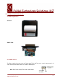
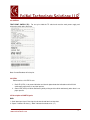
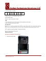
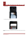
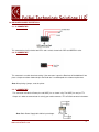
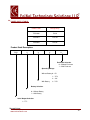
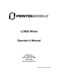
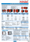
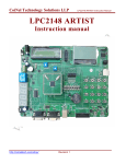
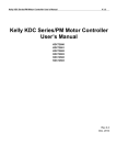
Thermal Printer
User Manual
www.coineltech.com
1
Document Title: Thermal Printer User Manual.
Version: Ver. 1
th
Date: 5 December 2014
Author: Sham Kumar V H
Technical Support E-mail: [email protected]
Technical Discussion Forum: www.coineltech.com/forums
Company Contact Information
CoiNel Technology Solutions LLP No-32,
nd
2 Floor,
HAPBCO Tower,
RPC Layout, Hampinagar, Bangalore560104
Ph: 080-23154423
www.coineltech.com
2
Table of Contents
1. Board Features
4
2.0 Thermal printer interface board
5
2.1 Outward appearance
5
2.2 Power Supply
5
2.3 SWITCH
6
2.4 LEDs
6
2.5 Description of UART Signals
7
2.6 Process of Loading the Thermal Printer
8
3.0 On Board Connector Details
9
4.0 Power Supply Table
10
www.coineltech.com
3
1. BOARD FEATURES:
The thermal printer has the following features
1. Interface: UART, RS232 or TTL Connection Out.
2. Baud rate can be changed. (From 1200 to 115200)
3. Images print Support. (As per user configuration through UART only).
4. 3 Fonts Support
2 English fonts (Fixedsys and Courier)
Regional Language font – Hindi (Kannada/Telugu/Guajarati as per the customer requirement)
5. Text File (.txt) content Print Support.
6. Bar Code Support Max length of 11 values (Includes alphabets and numbers)
7. Paper feed switch and Test print Switch is given in the onboard.
8. Power: 12V/3A (Product Code) / 7.5V/3A (Product Code) / 5V/3A (Product Code) Powered via
adapter or variable power supply.
9. Supported Printer:
a. 2 inch --- FUJITSU: FTP-628MCL103
b. 3 inch --- FUJITSU: FTP-628MCL103
10. The Board dimensions 60x30mm.
11. It has Two LEDs Pin outs.
www.coineltech.com
4
2.0. THERMAL PRINTER ENCLOSURE:
2.1 Outward appearance:
TOPVIEW:
FRONT VIEW:
2.2 POWER SUPPLY:
The Power supply to be used as per the Power supply Table 4.0 .The power supply connector pin is J3
in the Thermal printer Board. Details are shown in below figure.
Note: Refer Power Supply Table 4.0 for input Voltage.
www.coineltech.com
5
2.3 SWITCH:
TEST PRINT SWITCH (TP): For test print hold the TP switch and reset the main power supply and
release the switch after some time.
Note: Current Baudrate will also print
2.4 LEDS:
Board consists of 2 LED Pin outs.
1. Red LED (LED1) is for power indication and also for platen detection indication and it will blink
continuously when there is no platen present.
2. Green LED (LED2) will blink continuously while printing and also blink continuously when there is no
paper present.
2.5 Description of UART Signals:
RXD:
1. Serial data input signal. Data signal to be transferred from host to printer.
2. “Space” indicates no data (=), “Mark” indicates that data exists (= 1)
www.coineltech.com
6
3. The data format is as follows
Start
B0
B1
B2
B3
B4
B5
B6
B7
Stop
Length of stop bit is 1 bit fixed Data length is 8bits
fixed Parity Bits: None
Start bit is “Space” and stop bit is “Mark”
TXD:
1) Serial data output signal. Data signal to be transferred from printer to host.
2) Other functions are the same as RXD.
CTS: Not Used
RTS: RTS is an active low output which notifies the other device when it can receive data by driving
the pin low. The External device has to scan for this pin and transmit data only when the pin is low.
RTS = logic 0, mean that the module is ready to receive data.
Note: It will work without RTS pin also.
GND: Signal Ground.
2.6 Process of loading the Thermal Printer
1. Remove the platen slowly
www.coineltech.com
7
2. Replace the paper
3. Load the platen back to its position.
Note: Make sure that the platen is placed properly. After placing the platen the motor will rotate for some time
and stops.
www.coineltech.com
8
3.0. ON BOARD CONNECTOR DETAILS:
3.1. J1 CONNECTOR
This connector basically includes two LED’s and a switch, the two led’s RED and GREEN in color.
3.2. J2 CONNECTOR
This connector is used for baud rate setting. If the connector is open the Baud rate will be 9600 and if we
place a Jumper on above shown two pins the Baud rate is varied depends on customer requirement.
Note: After placing a jumper, reset the printer.
3.3. J3 CONNECTOR
This connector includes the Power pins and UART pins as shown in fig. The UART pins are just TTL
Output so in order to communicate via serially you need to connect a TTL to RS232 converter in between.
Note: Refer Power Supply table 4.0 for input voltage.
www.coineltech.com
9
4.0. POWER SUPPLY TABLE:
Product Code
Voltage/Amps
TPS21001
5V/3A
TPS21011
7.5V/3A
TPS21021
12V/3A
Product Code Description:
TPSX
X
X
X
X
Enclosure Selection
0 – Without Enclosure
1 – With Enclosure
Operating Voltage
Without Battery 0 – 5V
1 – 7.5V
2 – 12V
With Battery
3 – 7.5V
Battery Selection
0 – Without Battery
1 – With Battery
Serial Output Selection
1 – TTL
Thermal Printer
www.coineltech.com
10
Selection (TPS)
2 – 2 Inch Thermal Printer
3 – 3 Inch Thermal Printer
www.coineltech.com
11
For any technical discussion related to the product with our team and various users, visit and post
your questions at
www.coineltech.com/forums
READER RESPONSE
It is our intention to provide you with the best documentation possible to ensure successful use of the
product. If you wish to provide your comments on organization, clarity, subject matter, and ways in which
our documentation can better serve you, please mail your comments to [email protected] or
call our Technical Publications Officer at (+91) 80-23154423.
Please list the following information, and use this outline to provide us with your comments about this
document.
1. How does this document meet your hardware and software development needs?
2. Do you find the organization of this data sheet easy to follow? If not, why?
3. What additions to the data sheet do you think would enhance the structure and subject?
4. What deletions from the data sheet could be made without affecting the overall usefulness?
5. Is there any incorrect or misleading information (what and where)?
6. How would you improve this document?
7. How would you improve our software, systems, and products?
After-sale Service
We have special Technical Support Engineers to provide support and consultation in forms of
telephone, E-mail and so on.
TEL: +91-80-23154423
Technical Support E-mail: [email protected]
www.coineltech.com
12
Disclaimer
CoiNel Technology Solutions LLP provides the enclosed document under the following
conditions:
This document is intended for use for ENGINEERING DEVELOPMENT, DEMONSTRATION and
EDUCATION OR EVALUATION PURPOSES ONLY. As such, the document being provided are not
intended to be complete in terms of required design, marketing-, and/or related protective considerations,
The user assumes all responsibility and liability for proper usage of the document. Further, the user indemnifies
CoiNel Technology Solutions LLP from all claims arising from the handling or use of the documents.
EXCEPT TO THE EXTENT OF THE INDEMNITY SET FORTH ABOVE, NEITHER PARTY SHALL BE
LIABLE TO THE OTHER FOR ANY INDIRECT, SPECIAL, INCIDENTAL, OR CONSEQUENTIAL
DAMAGES.
No license is granted under any patent right or other intellectual property right of CoiNel Technology
Solutions LLP covering or relating to any machine, process, or combination in which such CoiNel
Technology Solutions LLP products or services might be or are used.
Information in this document is believed to be reliable and accurate. However, CoiNel Technology Solutions
LLP does not give any representations or warranties, expressed or implied, as to the completeness or
accuracy of such information and shall have no liability for the consequences of use of such information.
CoiNel Technology Solutions LLP reserves the right to make changes to information published in this
document, at any time and without notice, including without limitation specifications and product
descriptions. This document replaces and supercedes all information supplied prior to the publication hereof.
Trademark
All referenced trademarks, product names, brands and service names are the property of their respective
owners.
www.coineltech.com
13