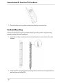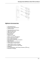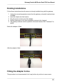
1
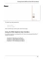
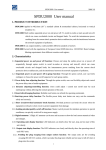
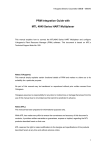
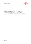
SmartZone™ GatewayEnabled
MS Series Rack PDU
User Manual
Release 1.0
Issue 1.0
Gateway-Enabled MS Series Rack PDU User Manual
Copyright © 2014 Panduit Corp. All rights reserved. No part of this book shall be reproduced, stored in a retrieval system, or transmitted
by any means, electronic, mechanical, photocopying, recording or otherwise, without written permission from Panduit. No patent liability
is assumed with respect to the use of the information contained herein.
Although every precaution has been taken in the preparation of this book, Panduit assumes no responsibility for errors or omissions.
Neither is any liability assumed for damages resulting from the use of the information contained herein.
-2-
Gateway-Enabled MS Series Rack PDU User Manual
Table of Contents
SmartZone™ Gateway-Enabled MS Series Rack PDU
Contacting Panduit
Symbols Used
Equipment Overview
Box Contents
Cable Details
Model Numbers
Pre-Installation
Installation
Product Inspection
Plug Connection
Hardwiring
Vertical Mounting
Horizontal Mounting
SmartZone 1RU Inline Meters
Optional Accessories
Additional Required Items
Safety Precautions
Servicing
Product Safety Warnings
Rules
Environmental Specifications
Bonding
Hardware
LCD Display
Reset Button
Mode Button Operation
Bootloader Startup
Firmware Recovery Mode
Application Startup
Internal Error Notification
Gateway User Interface
Access the PDU Graphical User Interface
Using the PDU Graphical User Interface
Appendix A - Temperature Sensor Adapter Installation
New Installations
Existing Installations.
Fitting the Adapter In-line.
4
4
4
6
6
6
7
8
9
9
9
9
10
12
12
13
14
14
14
14
15
16
16
17
17
17
18
18
18
18
19
20
20
21
22
22
23
23
-3-
Gateway-Enabled MS Series Rack PDU User Manual
SmartZone™ Gateway-Enabled
MS Series Rack PDU
Gateway-Enabled MS (Monitored and Switched) Series Rack PDUs manage and distribute power to multiple power devices through a single power connector. This PDU
allows you to access, configure, and manage power consumption and environmental
parameters from remote locations.
The MS Series PDU monitors per-phase power, voltage and current, per-branch current,
and includes the ability to switch the power to each outlet off or on.
SmartZone™ Gateway-Enabled
PDUs are available in a wide
range of configurations and
power connections and outlets
and can be mounted vertically or
horizontally.
Contacting Panduit
For Technical Support on PDU hardware and associated software, please contact Panduit Technical Support using one of the following methods:
1-866-721-5302 (toll-free)
Monday-Friday, 7:30 am - 5:00 pm CST
[email protected]
Symbols Used
Symbol
Description
Danger – Electric Shock Hazard
Warning – Possible Safety Hazard
Primary Earth Ground
-4-
Gateway-Enabled MS Series Rack PDU User Manual
Symbol
Description
Secondary Earth Ground
|
ON
O
OFF
-5-
Gateway-Enabled MS Series Rack PDU User Manual
Equipment Overview
The power inlet/cord(s) connects the PDU to the electrical power source. The LCD displays the current load for each input feed or electrical phase per input feed.
Box Contents
The SmartZone Gateway-Enabled Rack PDU box contains the following:
l
l
l
l
l
Gateway-Enabled Rack PDU
Configuration Cable
CD
Mains Adapter
External Grounding Stud
Cable Details
l
l
l
l
l
63A single and three phase feed cable – 10mm² (0.40 inches²) conductors:
HO7 cable type terminated with (1P) 3-pin 63A commando and (3P) 5-pin 63A commando (IEC60309)
32A single and three phase feed cable – 6.0mm² (0.23 inches²) conductors:
HO7 cable type terminated with (1P) 3-pin 32A commando and (3P) 5-pin 32A commando (IEC60309)
16A single and three phase feed cable – 2.5mm² (0.10 inches²)conductors:
HO7 cable type terminated with (1P) 3-pin 16A commando and (3P) 5-pin 16A commando (IEC60309)
13A single phase feed cable – 1.5mm² (0.06 inches²): HO7 cable type terminated with 3-pin UK plug
10A single phase feed cable – 1.0mm² (0.04 inches²): HO7 cable type terminated with 3-pin IEC C14 Plug
For IEC C-20 inlet PDUs, a customer-supplied cord is used for connection to the power
source. The connection end to the PDU has an IEC C-19 plug for connection to the
PDU. The opposite end of the cord shall have a plug suitable for connecting to the customer supplied receptacle. The cord and plug shall be rated for 20A in North America
and 16A outside of North America. The connection to the PDU should be made prior to
connecting to the power source
-6-
Gateway-Enabled MS Series Rack PDU User Manual
Model Numbers
The following table lists the specifications for the Gateway-Enabled Rack PDU model
numbers.
Horizontal
IQ Adapter
HC-wwwVxxA
IM-wwwVxxA
HD-wwwVxxA
IL-wwwVxxA
HL-wwwVxxA
Single Inline
HM-wwwVxxA
GM-wwwVxxA
HP-wwwVxxA
GL-wwwVxxA
HS-wwwVxxA
Dual Inline
Vertical
LM-wwwVxxA
VC-wwwVxxA
LL-wwwVxxA
VD-wwwVxxA
Quad Inline
VL-wwwVxxA
AM-wwwVxxA
VM-wwwVxxA
AL-wwwVxxA
VP-wwwVxxA
Under the Floor
VS-wwwVxxA
UM-wwwVxxA
In the tables above, www is the voltage for single phase or 3-phase and xx is the possible current associated with the voltage. Refer to the chart below for valid International
and U.S. values.
International
Voltage
240, 415
U.S.
Current
Voltage
Current
10, 13, 16, 20, 30,
32, 48, 63
120, 208
15, 20, 30, 50,
60, 80
-7-
Gateway-Enabled MS Series Rack PDU User Manual
Pre-Installation
The Gateway-Enabled Rack PDU products covered by this guide are designed to be
installed within EIA racks and cabinets. Use of this product in other applications is
acceptable, but other precautions may be required to allow for specific installations not
covered by this guideline.
-8-
Gateway-Enabled MS Series Rack PDU User Manual
Installation
The Gateway-Enabled Rack PDUs are designed to be installed within 19” rack cabinets.
Use of this product in other applications is acceptable, but other precautions may be
required to allow for specific installations not covered here.
Product Inspection
Before installing your PDU, ensure that it has been inspected. If the product has any visible signs of damage please contact Panduit customer support at 800-777-3300 or
[email protected]. Please register your product to receive notification of firmware and
product updates at: http://bit.ly/1aXKhr1
Plug Connection
This product is intended to be connected by the customer and must be installed by a
competent person in compliance with all local and national regulations.
Hardwiring
This product is intended to be hardwired by the customer. It must be installed by a qualified electrician in compliance with all local and national regulations.
1. To install the power cable, remove the securing screws on the removable user
panel.
2. Connect the conductors to the rack PDU terminals, in line with the terminal markings provided.
-9-
Gateway-Enabled MS Series Rack PDU User Manual
3. Ensure that the cover is replaced and secure before commissioning.
Vertical Mounting
Panduit recommends using the provided external grounding stud for supplementary
ground bonding to the rack metalwork.
1. Insert the tool-less mounting buttons into the fixing holes on the back of the rack/cabinet.
2. Install the PDU using the bracket mounting buttons and the mounting brackets located at either end of the PDU.
- 10 -
Gateway-Enabled MS Series Rack PDU User Manual
- 11 -
Gateway-Enabled MS Series Rack PDU User Manual
Horizontal Mounting
To mount this product horizontally, use the RU mountings via the brackets found at
either end of the PDU with the provided accessory screws, listed below.
l
Horizontal Models
North American units
(4) #10-32 x 1/2” MOUNTING SCREWS
(4) #12-24 x 1/2” MOUNTING SCREWS
Global units
(4) M6 x 20mm MOUNTING SCREWS
(4) #12-24 x 1/2” MOUNTING SCREWS
SmartZone 1RU Inline Meters
Install this product to the racks frame via the mounting plate holes found at either end of
the PDU using the provided mounting hardware. The mounting plate can be adjusted as
shown below.
- 12 -
Gateway-Enabled MS Series Rack PDU User Manual
Optional Accessories
l
l
l
l
l
l
l
l
l
l
l
l
l
l
l
l
l
l
l
l
l
Temperature Sensor
External Temperature Sensor
Humidity Sensor
Temperature/Humidity Sensor
Water Contact Sensor
Water Rope Sensor
Air Flow Sensor
Shock Sensor
Digital Input Sensor
Passive Infra-Red (PIR) Sensor
Door Contact (micro switch)
Door Contact (magnetic)
Standard Electronic Swing Handle Kit
Smoke Detector
Differential Pressure Transducer
Flashing Beacon with Sounder
Flashing Beacon with no Sounder
HID Access and Control Card Reader
Keypad Kit
LCD Display Module with Selector Switches (PCB only)
External LCD Display
- 13 -
Gateway-Enabled MS Series Rack PDU User Manual
Additional Required Items
l
l
l
Flathead and Phillips screwdrivers
Appropriate local AC power receptacle to power the PDU
Local active Ethernet port to communicate with the PDU
Safety Precautions
This section contains important safety and regulatory information that should be
reviewed before installing and using the Rack PDU.
Servicing
There are no user-serviceable parts inside these products. Any maintenance or repair
must be performed by approved service-trained personnel. Opening the unit will void the
product warranty.
Product Safety Warnings
Warning: Use only in dry locations. Indoor use only.
PDU hardware has an International Protection Rating of IPX0.
The installer must connect the power distribution unit to an electrical supply that has a
protective Earth conductor.
For pluggable equipment, the socket outlet should be installed near the equipment and
should be easily accessible.
Warning: For permanently connected equipment, a readily accessible disconnect
device should be incorporated external to the equipment.
Rack PDUs must be protected by a branch circuit protective device rated at the maximum rating of the product specified on the product rating label.
To avoid risk of overload, do not plug additional multiple outlet power distribution
devices into the power distribution unit socket outlets.
This equipment is intended only for installation and use in a Service Access Location in
accordance with the following installation and use instructions.
This equipment is designed to be installed on a dedicated circuit.
- 14 -
Gateway-Enabled MS Series Rack PDU User Manual
l
l
The dedicated circuit must have circuit-breaker or fuse protection.
Rack PDUs have been designed without a master circuit breaker or fuse to avoid
becoming a single point of failure. It is the customer’s responsibility to provide
adequate protection for the dedicated power circuit. Protection of capacity equal to
the current rating of the Rack PDU must be provided and must meet all applicable
codes and regulations. In North America, protection must have a 10,000A interrupt
capacity.
Warning: Always disconnect the power supply cord before opening to avoid electrical shock.
DANGER: High leakage current! Ground connection is essential before connecting supply!
DANGER: Double Pole/Neutral Fusing: The plug on the power supply cord must
be installed near the equipment and must be easily accessible.
Rules
These limits are designed to provide reasonable protection against harmful interference
when the equipment is operated in a commercial environment. This equipment generates, uses, and can radiate radio frequency energy and, if not installed and used in
accordance with the instruction manual, may cause harmful interference to radio communications. Operation of this equipment in a residential area is likely to cause harmful
interference in which case the user will be required to correct the interference at his own
expense.
Changes/modifications not approved by the responsible party could void the user’s
authority to operate the equipment.
- 15 -
Gateway-Enabled MS Series Rack PDU User Manual
Environmental Specifications
l
l
l
l
Operating Temperature: 0C to 40C
Transportation Temperature: -10C to 70C
Operating Humidity: 15% to 85% non-condensing
Transportation Humidity: 5% to 90% non-condensing
Bonding
This product contains an external earthing screw with a star washer, which should be
used for supplementary Earth bonding to the rack metalwork.
Bonding
Minimum Requirements for Bonding Conductors
Up to and including 32A
12 AWG
Up to and including 63A
8 AWG
Up to and including 80A
6 AWG
Screw Size
Over 16A, less than or equal to 40A
5mm
Over 40A, less than or equal to 63A
6mm
64A
7mm
- 16 -
Gateway-Enabled MS Series Rack PDU User Manual
Hardware
LCD Display
The display shows the firmware version number, device model number, serial number,
MAC Address, IP Address, and electrical readings. The display automatically scrolls
through the readings, which include:
l
l
l
l
l
l
Start Up messages
Configuration/serial/product number messages
Error/Status messages
Aggregate data
Single Phase data, 3-Phase Delta data, or 3-Phase Wye data
Branch current data (if the unit has breakers)
During normal operation, the mode button may be used to quickly advance through the
LCD display pages.
Reset Button
Push the Reset button using a non-metallic item, similar in size to a paper clip, to reset
the PDU device.
Warning: a metallic item, such as a paper clip, is not recommended as a reset
tool.
The reset tool should be inserted perpendicular to the surface of the device and pressed
until the button is reached and is actuated.
The reset tool should bump into the button within 1/8 of an inch of being inserted, and
should be lightly depressed and held for at least 1 second. The reset tool should never
be inserted more than 1/4 of an inch.
Resetting the PDU device starts the bootloader. Wait between 1 and 30 seconds for the
Display Backlight to blink on and off at a rate of 2 blinks per second. The bootloader
stays in this mode for at least 4 seconds (8 blinks) if no user operation is detected.
- 17 -
Gateway-Enabled MS Series Rack PDU User Manual
Mode Button Operation
Bootloader Startup
When the user presses and holds the Mode button, the Display Backlight switches to
one blink per second, indicating the bootloader is waiting for one of the following operations.
l
l
l
If the user releases the Mode button after two blinks, the backlight goes solid-on
and stays in the bootloader, entering the “firmware recovery mode”. See the "Firmware Recovery Mode" section (below) for more details.
If the user releases the Mode button after four blinks, the backlight goes solid-on
and attempts to boot the “backup firmware image”.
If the user does not operate the Mode button as described above, the Display Backlight is turned off. The “firmware updatable application image” continues loading.
Firmware Recovery Mode
The Gateway-Enabled PDU provides a firmware recovery mode in case a firmware
update is interrupted while in progress and fails to complete successfully.
Note: Do not power cycle or restart a device while a firmware update is in progress.
If a firmware update does not complete successfully, and the device fails to be operational after 30 minutes, contact Panduit Technical Support.
1-866-721-5302 (toll-free)
Monday-Friday, 7:30 am - 5:00 pm CST
[email protected]
Application Startup
When the application is ready, a message is displayed on the LCD:
Starting up…
The display backlight blinks quickly three times and remains lit.
The LCD then displays:
Hold MODE button to reset to defaults...
- 18 -
Gateway-Enabled MS Series Rack PDU User Manual
The application stays in this mode for at least five seconds. If no button operation is
detected, the application continues to normal system operation.
If the customer presses and holds the Mode button for five seconds, the following message displays on the LCD:
Hold MODE button more than 5 seconds to reset to defaults
If the customer continues to press and hold the Mode button, the following message displays on the LCD:
Reset to defaults is detected. Please release MODE button.
The customer should release the Mode button at this point. The following message displays on the LCD:
Device is Resetting to factory defaults.
If the customer does not operate the Mode button as described above, the application
continues normal system operation.
Internal Error Notification
After system start up is complete, the LCD screen may blink during normal operation of
the unit. This typically indicates a temporary or persistent internal error condition.
If the condition is persistent, the LCD screen displays the word "STATUS:" followed by a
hexadecimal code, similar to the following.
STATUS: 0x009000080
The hexadecimal code is a composition of per-outlet control, per-outlet monitoring and
per-phase monitoring status. For example, if a three phase Per-outlet Monitoring or
Switched unit loses a power phase, the status screen will reflect that communication to
those boards has been lost.
For definitions and recommended actions on status codes, provide the displayed hexadecimal number to Panduit Technical Support.
- 19 -
Gateway-Enabled MS Series Rack PDU User Manual
Gateway User Interface
The SmartZone Gateway-Enabled Rack PDU provides access to configuration, power,
and sensor data through the Gateway Graphical User Interface (GUI), using a standard
browser. There are several ways to connect to the device's Gateway GUI, depending on
your network configuration and the firmware revision of the device.
If the PDU has firmware revision 2.3.03 (or earlier), Static IP is the default. The configuration settings in this case are:
IPv4 Address:192.168.0.253
IPv4 Network:255.255.255.0
IPv4 Gateway:192.168.0.1
If the device has firmware revision 2.3.04 (or later), DHCP is the default, and one of the
following scenarios will be used.
l
If you have a DHCP Server available, connect to the appliance through that server,
using the PDU's IP Address.
Note: The IP address for the Rack PDU is displayed on the device's LCD screen after
the label IPv4
l
l
If you do not have a DHCP server, you can run one on your PC. To connect to the
device, use the IP address displayed on the LCD screen.
If you want to use automatic IPv4 address configuration, you must activate DHCP
on your PC and then connect directly to the PDU. This will give you an address on
the 169.254.0.0/16 network. You can then connect directly using the IP Address
displayed on the LCD screen.
Access the PDU Graphical User Interface
To access the GUI, open a web browser and enter the IP Address of the PDU. When the
login page opens, you will be prompted to enter a login and password.
- 20 -
Gateway-Enabled MS Series Rack PDU User Manual
The default login and password are:
Login:admin
Password:admin
After successful login, the GUI opens to the Overview page.
Using the PDU Graphical User Interface
For detailed information on working with the GUI, refer to the appropriate SmartZone™
Gateway User Manual:
l
l
l
l
SmartZone™ E24 Gateway User Manual
SmartZone™ EP042 Gateway User Manual
SmartZone™ EPA064 Gateway User Manual
SmartZone™ EPA126 Gateway User Manual
- 21 -
Gateway-Enabled MS Series Rack PDU User Manual
Appendix A - Temperature Sensor
Adapter Installation
Follow the instructions below to install the ZAHTLADT-02 v1.01.01 temperature sensor
adapter module. This adapter allows legacy sensors to provide more accurate temperature readings.
Note: This adapter does not work with the ZETHL-14 temperature sensor.
New Installations
Follow these instructions when you are installing a standard temperature sensor, but the
upgraded sensor input is required.
1. Plug the adapter directly into the back of the gateway, at the sensor port to be used
for temperature.
2. Plug the temperature sensor connector into the adapter.
3. Update the gateway firmware to the latest release. See "Hardware" for details.
- 22 -
Gateway-Enabled MS Series Rack PDU User Manual
Existing Installations.
Follow these instructions when the sensor is already installed along with the gateway.
1. Unplug the current temperature sensor from the gateway, noting the location where
it resided.
2. Insert the adapter into that location.
3. Plug the sensor into the end of the adapter.
4. Perform these steps for all other temperature sensors to be changed.
5. The gateway firmware must be updated to the latest firmware. See "Hardware" for
details.
Before the adapter is fitted:
After the adapter is fitted:
Fitting the Adapter In-line.
This procedure is not recommended, but it may be the only solution in some cases.
- 23 -
Gateway-Enabled MS Series Rack PDU User Manual
1. Using a patch lead from the gateway and an RJ45 Jack to Jack through connector
on its non-gateway end, plug the adapter RJ45 Plug into the through connector.
2. Plug either the RJ45 plug of a temperature sensor into the jack on the adapter or a
patch lead with the temperature sensor on the end.
- 24 -