1
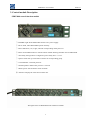
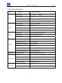
SPDU2000 User manual
2006-V0
SPDU2000 User manual
1. PRODUCT INTRODUCTION
SPDU2000 Applied to 482.6mm (19″) standard cabinet & nonstandard cabinet, horizontal or vertical
installed, 1U;
SPDU2000 Multi outlets sequential power on and power off. To avoid in-rushes at start-up and turn-off,
which can cause overloaded circuits and dropped loads. To avoid the instantaneous power
resulting from the current shock protection device malfunction, and the interference between
the network equipment of pollution;
SPDU2000 8 way output modules, could assemble different standards of sockets
SPDU2000 Accord with the regulations of European Union ROHS directive, 110/220VAC Rated voltage,
Meeting requirements from different countries and regions;
2. Characteristics
2.1.Sequential power on and power off function: Choose and setup the outlets power on or power off
sequentially through option switch to avoid in-rushes at start-up and turn-off, which can cause
overloaded circuits and dropped loads, the instantaneous power resulting from the current shock
protection device malfunction, and the interference between the network equipment of pollution;
2.2. Sequential power on and power off in-group function: Through the option switch, user can freely
configure or choose the power on/off sequence for each group outlets.
2.3. Power delay time adjusting function: Through the option switch, user can flexibility adjust and control
the power delay time of multi-equipments.
2.4. Dynamic adjusting/controlling function: Users could adjust / control turn on/off state for each
outlet/group without affecting the normal operation of this unit.
2. 5 Reset/refresh keeping function: Reliable reset button can refresh the operating commands.
2.6.Start/stop power delay function: The flexible power delay start button can carry out the commands
safely and correctly.
2.7. Short circuit/overload automatic break function: Overload protector can break the circuit when the
equipment overload or short circuit to protect equipment from damage.
2.8. Avoiding mistake/quickly switch off function: Master switch prevent the mistaken operation, in special
conditions; can quickly switch off to stop power supply.
2.9. Digital ammeter: 3.5digit AC ammeter can be true and accurate to show the load current numerical value
and changes.
2.10. Operating state display function: LED indicators can timely show the start, stop and run state of this
unit clearly.
2.11. Output state display function: The LED indicators can clearly and directly show the operating state of
each PDU units.
2.12. Avoiding the plug escaping from output sockets function: The output units are the avoiding
escaping IEC320 C13 sockets, which can make the plug more reliable and not easy to fall off when it
plugs into the socket.
1
SPDU2000 User manual
2006-V0
3. Control module Description
SPDU2000 control function module
①.POWRE: Light when SPDU2000 connect to AC power supply.
②.RUN: Flash, when SPDU2000 operate normally.
③.Bus A Indicators (1-8): Light, when the corresponding outlet power on .
④.Reset: Press RESET button to refresh outlets without affecting ON/OFF state of SPDU2000.
⑤.Time delay setting button: Configure the power delay time(0~15s).
⑥.Option switch: Set up on/off state of outlets for corresponding group.
⑦.Circuit Breaker: Overload protector.
⑧.Start/Stop button: Effect after press for 3 seconds.
⑨.Master power switch: Master switch for PDU.
⑩.Ammeter: Display the total current of this unit.
The figure below is SPDU2000 control function module:
2
SPDU2000 User manual
2006-V0
4. Operation of SPDU control function module
4.1. Power start: When SPDU2000 connects the power supply, set up the required outlets and power delay
time. Then switch on, the “run” indicator flashes frequently and these outlets will sequential start on.
After finished the start, the “run” indicator flashes slowly (about 0.5s/t).
4.2. Start/stop after power start: Please press start/stop button for 3 seconds after power start (the “run”
indicator flashes frequently after this operation valid). And then loosen the button to enter the stop
program, outlets power down sequential. After finish power down, the “run” indicator flashes slowly
(about 1s/t).
If you want start it again, you can press start/stop button for 3 seconds to enter the start
program (the “run” indicator flashes frequently), outlets will sequential power on.
4.3. Refresh after power on (effective only in “on” situation): when you need to modify the state of output
equipment and power delay after power on, please press “reset” button.
4.4. Grouping: Press start/stop button to start the power, when the “run” indicator flashes frequently (about
0.25s/t), Loosen the start/stop button to enter the grouping program. When you need to select grouping
and make the selected outlets be “ON”, press “reset “button, the “run” indicator flashes frequently for
one second indicate grouping is successful; If the “run” indicator flashes frequently intermittently, it
fails in grouping. If you want to reset , you should follow the above way to operate again. You can stop
the power button after grouping if you don’t want to continue. Press “reset” button when you enter the
grouping program, the former grouping record will be cleared away.(please attention: when
grouping (should be over one way), you can’t set again!).
4.5. Reset the default setting of leaving factory: Enter the grouping program and make all the buttons off,
press “reset” once again and turn off the power button, then the program is finished.
4.6. Configure the power delay time: You can set the power delay time between 0 and 15 seconds. When
option” 1” is on, it means 1 second power delay; When option” 21” is on, it means 2 seconds power
delay; When option” 3” is on, it means 4 seconds power delay; When option” 4” is on, it means 8
seconds power delay; When all options are on, it means 15 seconds power delay. When all options are
off, it means 0 second power delay.
4.7. Quickly switch off when in trouble: When in urgent trouble, press on-off switch button to stop power at
once.
3
SPDU2000 User manual
2006-V0
5. Technology Parameters
Item
Capability
Main description
Rated voltage
110/250VAC
Max. Current
16~32A
50/60HZ
Input
Cable specification
3× 2.5mm²×3M; 3× 4.0 mm²×3M
Plug with the cable
Different standards plug and IEC60309 plug
Outlet standard
IEC320 C13/IEC60906/
Outlet quantity
Max.8 way
Rated output current
10A
Max. Output current
16A/Max.32A
Rated power
3.5 digit, digital AC ampere meter
Output status
8 way Green LED indicator
Running status
1 way LED indicator
Master switch
Avoiding mistaken operation warping button
Output option switch
8 way DIP button
Modify power delay button
4 way DIP button
Reset button
Press-button
Start button
Press-button
Overload protector button
16A overload protector
Mounting method
Horizontal installation, 1U space
Dimension
L×W×H = 482.6×68×44.4mm(19″Standard、1U)
Mounting length
465mm
Output
Display
Control
Mounting
Product size
Weight
Kg
Power consumption
Approximately 2~6W
Working temperature
0℃-55℃
Relative Humidity
10-90%
Environment
4