1
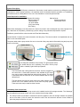
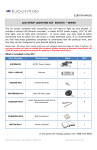
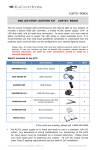
Automatic Refill System
User Manual
256-229-5551
24-Hour Technical Support: 888-391-7669
1-800-745-8599
www.snowmasters.com
30 Day Warranty © 2009 SnowMasters
System Description:
This Automatic Fluid Refill System maintains the fluid levels in small machine reservoirs by refilling them automatically from a bulk storage container. It is especially useful for extended machine operation or in installations
that makes reservoir refilling difficult. This unit is not intended for corrosive/explosive fluids.
Items Required for Installation:
Refill System Kit including
Pump Control Unit
Float Assembly
1/4" Hose Clamp
5/16" Hose Clamp
Roll Tubing
Optional Items
Mounting hardware
Outdoor/Wet Cover
Please Note: Attempting to use this product in a manner for which it was not designed may cause improper function, destruction of the product, personal injury and/or voiding of any warranties expressed or implied.
Familiarize yourself with the control module and Float Switch Assembly.
Control Module: Contains the control electronics and the pump. The control module is encapsulated and contains no user-serviceable parts.
The power cable and the pump suction line are on one side of the pump and the float switch plug and pump outlet are on the other.
CONTROL MODULE
CONTROL MODULE
PUMP
DISCHARGE
POWER
CABLE
PUMP
SUCTION
FLOAT
SWITCH
CONNECTION
Two diagnostic indicators are provided. The green power indicator shows that the unit is operating. The yellow “call for pump”
and the “standby” light indicate pump status.
The Float Switch has a wiring harness connector, which is plugged into
the control box. A float switch extension cord available as an accessory can be used to extend the float switch wiring harness. The switch
is activated when the fluid level in the remote container falls to a predefined level.
The float switch also has two holes at the top to allow insertion of the
suction line for the machine and the fill line from the pump system.
These two holes may be used for either function.
Installation of the Control Unit:
Overview: The “suction” line on the pump control unit is installed into the bulk storage container. The “discharge”
line is installed from the pump control unit to the container that is being refilled.
1. The Pump Control Unit should be mounted as close as possible to the bulk storage container as possible
and no more than 15 feet of suction line should be used. This will reduce the amount of time needed to
prime the pump the first time it is used.
The electronics inside the Pump Control Unit have been encapsulated in urethane. Care should be used to
avoid allowing fluid to enter the enclosure to prevent the fluid from false triggering the pumping system.
2. Insert the switch extension cord into the pump system and extend the float switch assembly to the machine
reservoir. DO NOT CUT THE SWITCH EXTENSION CORD. Excess cord can be left rolled up.
3. Place the 1/4" hose clamp over one end of the hose and attach the hose to the barbed outlet of the pump.
Fasten the hose clamp over the tubing to secure the hose to the fitting. Extend the hose to the machine reservoir.
4. Attach a short piece of tubing to the suction fitting of the pump and secure that fitting with the 1/4" hose
clamp. This is important to prevent air infiltration into the fluid lines. The other end of the suction line should
be placed into the bulk storage. Insure that the inlet of the suction let will remain submerged in the fluid even
as the container empties.
5. Electrical Power should be 110-volt or 220-volts (approx.) and appropriate for the pump control model you
are installing. The system can operate on either 50 or 60 Hertz. 220-volt installations may require “hardwiring” or installation of a suitable power plug. Installation of a Ground Fault Interrupt is recommended.
Installation of the Float Switch Assembly:
6. Remove the cap from the machine reservoir and the machine suction tube. It may be a good idea to retain
the cap for replacement should the fill system is no longer required. Insert the tube from the machine into
one of the holes on the top of the Float Switch Assembly. It may help to cut the end of the tubing at a steep
angle to get the tubing started in the hole.
7. Insert the tubing from the Pump Control Module into the other hole. Again, it may help
to cut the tubing at a steep angle to get the tubing started.
8. Plug the Float Switch Assembly electrical connection into the switch extension cord.
9. Insert the float switch assembly into the machine reservoir, with the float situated towards the bottom of the
reservoir and tighten the float switch onto the reservoir. It is imperative that the float on the switch is free
from obstruction and that during the fill cycle the fluid entering the machine reservoir does not spray directly
onto the float. Failure to observe this notice may cause improper operation of the refill system.
Testing for Proper Operation:
When power is applied to the Pump Control Module the green power Indicator will illuminate. When the
float on the float switch assembly falls signifying a need to refill the machine reservoir, the yellow “Call for Pump”
will illuminate. The control module will then turn on the pump. Under normal circumstances the yellow and green
light will always be on together.
The pump system will fill the container within 4-5 inches of the top and then stop filling until the fluid level
in the machine reservoir has lowered approximately 1 to 2 inches. This system allows for plenty of time to refill
the bulk storage container by providing significant fluid in the machine reservoir at all times.
Troubleshooting:
The Auto Refill System is designed to tell the user if any error occurred to it. We have different cases that could
occur while the pump is in use.
Case 1: Full Level Fluid The pump is off and it is connected to electricity. The power LED (green) is ON and pump-call LED (yellow) is OFF.
Case 2: Low Level Fluid The pump is 1 min ON/ 1 min OFF, power LED (green) is ON and pump call LED (yellow) is ON when pump turns ON and blinks
when the pump turns off each minute.
Case 3: Float Sensor Short This is a short in the wire from the pump to the float sensor. If for instance, someone accidentally scraped off the insulation
and the un-insulated part of the wire went into a puddle. The pump is connected to electricity. The power LED (green) blinks 2 times then stops for 2 sec
and so on. The pump-call LED (yellow) is OFF.
Case 4: Line Cut This is were either one of the two wires are cut or if there is an open circuit. For example, if the float sensor has become disconnected.
The pump is connected to electricity. The power LED (green) blinks 3 times then stops for 2 sec and so on. The pump-call LED (yellow) is OFF.
SYMPTOM
SUGGESTION
Green Power Light does not illuminate and pump does not function
Insure proper power is connected to Pump Control Module. There
are no serviceable parts in the Module.
Pump is Not Pumping
Green Power Light - On
Yellow Call for Pump Light - On
Yellow Pump light – On
Heat Safety switch tripped typically caused by pump running in excess of 10 minutes continuous. Wait 30 minutes and try again.
*Float switch is calling for refill
Pump is Not Pumping
Green Power Light – On
Yellow Call for Pump Light – Off
Yellow Pump Light – On
*Float switch not calling for refill
Pump runs continuous
Green Power Light – On
Yellow Call for Pump Light – On
Yellow Pump Light – On
*Over-filling container
Pumps runs but will not prime
Pump damaged. Return to factory for evaluation.
Internal safety switch is tripped and Float Switch is NOT calling for
fluid. Disconnect power for 30minutes and try again.
Pump damaged. Return to factory for evaluation.
Check for free movement of float switch.
Check for fluid that may be shorting out the Float Switch Assembly,
specifically around connections to the extension cord and pump control module. Fluid around the electrical connections will cause a false
trigger of the pump system. Check fluids around connectors and the
length of the connecting wire. Unplug float-switch at the pump, if the
pump remains “ON”, fluid is inside the pump control – disconnect
power, with Float-switch plug out, allow liquid to drain through the
hole and dry out.
Pump is dry. This system utilizes a magnetically driven piston pump
that uses the fluid as a lubricant and buffer. Disconnect inlet line and
put a few drops of water in both the suction and discharge end of the
pump. Dry operation will damage pump.
Warnings:
1. The pump assembly is not water proof and should be located in a dry place.
2. Insure the float sensor switch can float freely in the fluid tank.
Warranty:
Day warranty when installed according to manufacturer instructions
Automatic Refill System is backed by a 30
lifetime
and the refill system is not allowed to run without fluid. Defective product must be returned for evaluation and
warranty service. Liability limited to repair of replacement of the pump system at Manufacturers sole discretion.