1
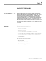
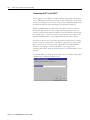
Integrated
Architecture
Global
Supply & Local
Capabilities
Complete
Automation
Superior
Value-Added
Services &
Expertise
World Class
Products
A Complete
IntelliCENTER™
Workshop
Introduction to
IntelliCENTER
Instructor Lab Manual
Table of Contents
Introduction to IntelliCENTER
A Complete IntelliCENTER Hands-On Lab Demo
Setup Instructions
Equipment Required . . . . . . . . . . . . . . . . . . . . . . . . . . . . . . . . . . . . . . . . . . . . . . . . i
Setup Instructions . . . . . . . . . . . . . . . . . . . . . . . . . . . . . . . . . . . . . . . . . . . . . . . . . . ii
Take Down Instructions . . . . . . . . . . . . . . . . . . . . . . . . . . . . . . . . . . . . . . . . . . . . . iv
Chapter 1
IntelliCENTER Lab Kit
Overview . . . . . . . . . . . . . . . . . . . . . . . . . . . . . . . . . . . . . . . . . . . . . . . . . . . . . . . 1-1
Chapter 2
Connecting to the Motor Control Center (MCC) . . . . . . . . . . . . . . . . . . 2-1
Chapter 3
Monitor View . . . . . . . . . . . . . . . . . . . . . . . . . . . . . . . . . . . . . . . . . . . . . . . . . . . 3-1
Chapter 4
Monitoring a Starter with Electronic Overload . . . . . . . . . . . . . . . . . . . . . 4-1
Chapter 5
Additional IntelliCENTER Features . . . . . . . . . . . . . . . . . . . . . . . . . . . . . . . 5-1
Chapter 6
Spreadsheet View . . . . . . . . . . . . . . . . . . . . . . . . . . . . . . . . . . . . . . . . . . . . . . 6-1
Chapter 7
IntelliCENTER Advanced Features - E3 Configuration . . . . . . . . . . . . . . 7-1
Publication 2100-RM003B-EN-P - March 2003
ii
Table of Contents
Chapter 8
Workspaces . . . . . . . . . . . . . . . . . . . . . . . . . . . . . . . . . . . . . . . . . . . . . . . . . . . 8-1
Chapter 9
Preferences . . . . . . . . . . . . . . . . . . . . . . . . . . . . . . . . . . . . . . . . . . . . . . . . . . . . 9-1
Chapter 10
More Customization . . . . . . . . . . . . . . . . . . . . . . . . . . . . . . . . . . . . . . . . . . . 10-1
Chapter 11
Saving IntelliCENTER Data . . . . . . . . . . . . . . . . . . . . . . . . . . . . . . . . . . . . . 11-1
Publication 2100-RM003B-EN-P - March 2003
A Complete IntelliCENTER Hands-On Lab Demo
Setup Instructions
Equipment Required
MCC Demo Cases
CAOTM IntelliCENTER Demo Demo (Demo I) P/N 2100-ES10-SUITCASE-850SHK.
This demo case features three units and will support all lab exercises. This is
the demo primarily used with CAOTM events and GMS Training. This demo
is heavy (120#) an usually comes crated in a wooden crate.
Computer Requirements:
Operating system: Windows 98, NT4, 2000, XP
Processor: PIII 650 MHz minimum
Video: 1024 x 768 resolution w/65535 colors
Disk space: 250MB
Mouse: Microsoft compatible
RAM: Windows 98 - 64Mb (128Mb recommended)
RAM: Windows 2000, NT4, XP - 128Mb (256Mb recommended)
Network Interface Requirements:
This lab exercise requires a direct DeviceNet connection. (IntelliCENTER
software is capable of connecting via Ethernet, ControlNet or DeviceNet.)
DeviceNet Interface Hardware:
Laptop Computer: 1784-PCD (PCMCIA) or 1770-KFD (serial)
Desktop Computer: 1784-PCIDS (PCI) or 1770-KFD (serial)
Software Required:
A working copy of IntelliCENTER™ software is required.
This software includes:
Adobe® Acrobat Reader®
AutoDesk® Volo™ View Express
Microsoft™ Internet Explorer
Rockwell Software RSLinx Lite™
IntelliCENTER Software
(Note that IntelliCENTER Software will not overwrite installed versions of
Acrobat or Volo View Express regardless of revision level/release number.
Also, Volo View Express will not be installed if the computer already has a
registered program, such as AutoCAD™, to open .dwg files.)
i
Publication 2100-RM003B-EN-P - March 2003
ii
A Complete IntelliCENTER Hands-On Lab Demo Setup Instructions
Setup Instructions
The following setup instructions apply to CAOTM supplied equipment only.
CAOTM equipment includes Allen-Bradley Industrial computers, monitors,
keyboards, mice, KFD interface modules and the DEMO suitcase. Setting up
the smaller demos set up in 2003 with another type of computer should be
intuitively similar.
In a typical Complete IntelliCENTER Workshop lab setup, there will be two
students working at each lab station. The hands-on lab suitcase demo will be
set on top of the worktable with the mouse, keyboard and monitor. The
computer will usually be placed under the table.
It is a two-person job to transport the demo case for placement onto
a table top.
ATTENTION
Be sure to lift demo cases with the legs - not the back, to
avoid risk of injury.
!
Connect the KFD module to COM1 on the desktop computer. Be sure to
tighten the connector into the port. Connect the cable from the demo case to
the KFD module. Engage the connector screws from the DeviceNet cable
into the KFD Module.
ATTENTION
!
DO NOT JERK THE DEMO CASES BY THE
HANDLES. Use the handles gently to avoid breaking
them. Once the handles are broken, moving the case will be
very difficult.
1. Open the cases on the tabletop. Be sure to lay the winged latch tabs flat,
to avoid accidentally catching clothing on them.
2. Locate the black power cord. Plug this cord into the switched outlet on
the side of the demo case and into a 120VAC power source.
3. The DeviceNet cable that connects the demo case to the computer
should be curled up in the left-hand side of the box. Uncoil this cable
and plug it into the matching port at the back of the computer.
a. Be sure to engage at least one of the screws - if the cable pops out,
Publication 2100-RM003B-EN-P - March 2003
A Complete IntelliCENTER Hands-On Lab Demo Setup Instructions
iii
communication will be lost and you may have to reboot the PC to
establish DeviceNet communication.
4. Connect the keyboard, mouse and power cords to the appropriate ports
at the back of the computer.
5. Depending on which computer you are using, there may be two VGA
ports on the back of the computer. One is on the mother board along
the edge of the chassis. The other port is on a card in one of the mother
board slots.
a. Use the port that is on the card in one of the slots.
b. Plug in the power cord into the back of the monitor.
6. Turn on the computer and the monitor. The Windows™ user ID is
“Administrator.” There is no password. Do not change the password
setup.
7. Turn on the power switch located on the outside of the demo case.
8. Turn on the two F100 circuit breakers on the lower left-hand side of the
case. As you turn on the disconnect switches, you should see the lights
on the pushbutton stations illuminate.
Note: During this lab, whenever a student needs to operate a unit, he or
she will press the lighted pushbutton.
9. Turn the rheostat down to zero.
10. Turn the selector switch to the OFF position.
11. Before starting the IntelliCENTER Software, reset the database by
clicking on the RESETDB shortcut icon on the desktop. Resetting the
database will remove all the changes (from software defaults) made by
the last user.
12. After resetting the software configurations, start IntelliCENTER
software and check hardware configurations.
•· Most often, it will be necessary to open the E3 monitor view and reset
the parameters monitored to those shown in chapter 7.
•· Also, it will be necessary to change the default configuration so that the
E3 is attempting to operate in 3 phase mode.
o Pick a parameter field - change parameter shown to
Parameter 27, "Single/Three Ph."
o Change this parameter to 3 phase.
o Click "Apply"
Publication 2100-RM003B-EN-P - March 2003
iv
A Complete IntelliCENTER Hands-On Lab Demo Setup Instructions
o If unsure how to make these changes - work through Chapter 7.
13. (Optional) Change the FLA setting on the dip switches on the SMP-3
from 2.0 A. to 3.5A.
Take Down Instructions
1. Make sure all the manuals are returned back to the envelopes - DSA, E3
and SMP-3.
2. Detach the DeviceNet cable from the back of the computer and curl it
up inside the case. Assure that the KFD module is properly stored.
3. Store the power cable inside the case.
4. Make sure all disconnect handles are in the OFF position or the case will
not close.
5. Close the cases, making sure to fully engage both latches. Make sure the
winged latch tabs are folded flat after latching to prevent breakage.
6. Exit the IntelliCENTER program and Windows in the usual manner do not just turn off the computers.
Publication 2100-RM003B-EN-P - March 2003
Chapter
1
IntelliCENTER Lab Kit
IntelliCENTER Lab Kit
IntelliCENTER Software allows the novice computer user to configure,
collect data and troubleshoot an intelligent Motor Control Center - without
requiring extreme expertise in industrial networks. As motor control
devices become more complex, the traditional industrial electrician is
challenged to maintain these devices. IntelliCENTER Software meets this
challenge head-on by providing an intuitive, pre-configured interface to
make this transition to higher technologies as simple as a few mouse clicks.
The purpose of this chapter is to familiarize the user with the various parts
of the Demo.
Overview
The major elements within the lab kit are:
•
DeviceNet Power Supply
•
DeviceNet Connections
•
Unit #1 - NEMA Starter with E3 Solid-state overload relay
•
Unit #2 - MCS Contactor with SMP-1 and DSA in 1/2 space factor unit
•
Unit #3 - NEMA Contactor with SMP-3 overload and GK61 module
•
Power Distribution
Each unit contains the following hardware:
1
•
Disconnect switch
•
Hand Off Auto selector switch
•
Illuminated Start/Stop pushbuttons
Publication 2100-RM003B-EN-P - March 2003
1-2
IntelliCENTER Lab Kit
Some of the disconnect switches
have shown a tendency to fall into
the OFF position under their own
weight. A rubber band is the easy
solution to this.
Disconnect Switch
The disconnect switch is the large black handle which is prominent on all three
starter units. On a real motor control center, the disconnect switch will be
connected to all three phases of incoming power. This switch is typically
connected to a 3-phase circuit breaker or a fusible disconnect. On the demo,
only the hot side of the 24VAC single-phase circuit is disconnected via a limit
switch connected to the disconnect handle.
Selector Switch
There is a Hand-Off-Auto Selector switch in each unit. As the units will not be
operated via remote control (IntelliCENTER software does control devices),
place the selector switch in “Hand” whenever it is necessary to operate a unit.
In a later exercise the position of this switch will be monitored via the
software.
Illuminated Push Buttons
There is one red and one green illuminated push button on each unit. Notice
the small unit (1/2 space factor unit) has 800E (small) buttons and the other
units have 800T standard buttons.
Publication 2100-RM003B-EN-P - March 2003
IntelliCENTER Lab Kit
1-3
Load
There are four parts to the load section located in the bottom left-hand side of
the demo:
•
Selector Switch Œ
•
Rheostat
•
•
Ammeter
Ž
•
Motor
•
Ž
•
Œ
•
The selector switch determines which unit is connected to the motor. The
leftmost position of the selector switch is OFF. The next three positions select
units in a clockwise rotation, starting with the single E3 unit on the left side of
the demo case.
The rheostat is in parallel with the motor. The purpose of the rheostat is to
divert current in increasing amounts until the overload trips. The capacity of
the power supply is 5A@24VAC.
The ammeter measures the total current through the motor and rheostat.
The motor is a 24VAC single phase motor.
If the DeviceNet Power supply is
turned off after communication has
been established, the PCIDS card in
the computer may lock up.
DeviceNet Power Supply
Next to the load there is a power supply providing the 24 volts DC needed for
DeviceNet. In a real MCC there would be a large 8A power supply. This demo
kit uses a 1A FLEX I/O power supply.
Publication 2100-RM003B-EN-P - March 2003
1-4
IntelliCENTER Lab Kit
DeviceNet Connections
There is a white metal plate with four ports located on the right side of both
halves of the demo unit. This plate represents the vertical wireway in a real
motor control center. A flat DeviceNet cable runs behind the wireway and all
of the ports are connected to the flat cable. There is a round cable that
connects the top port of the two wireways together. In a real IntelliCENTER
MCC, this cable would also be flat and would run behind the structure.
Note: Each unit has a cable running from a DeviceNet component to the
wireway port.
The Out A and Out B coils are only
activated via network command.
Operating the unit manually will not
energize either of these contacts.
Unit #1 - NEMA Starter with E3 Solid-state overload relay
The E3 solid state overload relay is connected in series with the NEMA
contactor and the load.
Notice the input LEDs located on the front of the E3. These LEDs illuminate
when there is a 24V signal on the input. Input #1 is connected to the auxiliary
contact on the starter. Operate the Hand-Off-Auto (HOA) switch and observe
which input is energized.
Notice the output lights on the E3. There are two output contacts that can be
operated by remote control on the E3. These contacts are typically used to
energize the coil on the contactor. In a reversing starter both contacts are used.
These outputs are labeled “OUT A” and “OUT B” on the overload. These
outputs will not be energized during this lab because the E3 will not be
operated by remote control.
Publication 2100-RM003B-EN-P - March 2003
IntelliCENTER Lab Kit
1-5
The blue button is a combination TEST/RESET button. If the E3 trips, it can
be manually reset by pressing this button. (The E3 can also be remotely reset
by a command from the network.) If the E3 starter unit is operating and this
button is pushed, then the E3 will execute a test trip. Some models of the E3
require the reset button to be held for three seconds before tripping.
There is a trip contact inside the E3 that breaks the coil circuit in case of an
overload or test trip. This contact is an addition to the two remote control
contacts. See page 2-20 of the E3 User Manual for a simple diagram of a
control circuit using the E3 overload.
SMP 1
Bull 100
MCSCont.
DSA
Unit #2 - MCS Contactor with SMP-1 and DSA in 1/2 space
factor unit
The SMP-1 is a solid-state overload relay connected in series with the
100-MCS contactor and the motor load. (Notice how T2 from the overload is
connected to L3 of the Contactor. This is necessary for single-phase
operation.) The SMP-1 does not have built in communication, so a DSA
(DeviceNet Starter Auxiliary) was added to monitor contact status and to
provide control.
The DSA has four input points. In this lab demo the Hand-Off-Auto switch is
connected to one of the inputs on the DSA. The auxiliary contact on the
SMP-1 solid state overload relay is connected to a separate input.
The DSA also has two output contacts. These contacts are rated for the
inductive load of (up to) a NEMA 5 starter.
Note: For this lab, the starter will not be controlled via the network.
The outputs on the DSA will not be used to control the starter.
Publication 2100-RM003B-EN-P - March 2003
NEMA
BULL
509 Starter
SMP-3
GK61
Interface
It has been discovered that the
demo kits were built with at least 2
different models (trip ranges) of
SMP-3.
The LED #1 (top) should turn from
red to green with movement of the
selector switch. LED #2 will turn to
green when the starter is energized.
These LEDs correspond to the inputs
on the GK61.
Unit # 3 - NEMA Contactor with SMP-3 overload and GK61
communication module
The SMP-3 is a solid-state overload relay with dip-switch settable parameters.
This overload is connected in series with the contactor and the motor load. As
in the SMP-1 unit above, we have routed one of the phases twice through the
SMP-3.
The SMP-3 has communications capability but does not have DeviceNet
capability. Turn the H-O-A selector switch to “AUTO” and note the change
in the input LEDs.
The GK61 module also has inputs built in to pick up status contacts local to
the unit. Turn the HOA selector switch to “AUTO” and note the change in
the input LED.
Note that the GK61 does not have output contacts (as do the E3 and DSA).
To remotely control this starter, you would send a DeviceNet command over
Publication 2100-RM003B-EN-P - March 2003
IntelliCENTER Lab Kit
1-7
the network to the GK61. The GK61 would then “tell” the SMP-3 to open or
close the SMP-3 contacts (via ScanPort).
Why is it important that the DeviceNet devices have inputs?
Suppose there were no inputs and the status of contacts in the units needed to
be monitored. The user would have to install an I/O chassis and run wires
back to the chassis for each contact desired. One premise of using DeviceNet
is to eliminate this control wiring. When inputs are provided on the devices,
control wires can be eliminated in favor of a single communication cable.
Power Distribution
Motor circuits are all 24VAC supplied by a 750VAC transformer behind the
black barrier. DeviceNet power is supplied by the 1A 24VDC Flex I/O power
supply. Note that the disconnect to a unit can be turned off, but the
DeviceNet device will still have power.
ATTENTION
!
The SMP-3 requires 120VAC, which is supplied to
terminals 50 and 60 of the SMP-3. The coil circuit uses
triacs that supply 120VAC to the coils. There is an
interposing relay so that the NEMA Contactor uses
24VAC coil. The terminals on the SMP-3 are finger safe;
however, a determined person may still contact 120VAC.
Please be careful.
Main power is provided by a 120VAC wall plug. This supply is switched where
the power cable connects to the demo case. Leave this switch on at all times.
1. Turn the selector switch to Unit #2. Activate the unit disconnect switch
(black handle) for Unit #2 and press the green lighted button. Observe
the full load motor current on the ammeter with the rheostat turned to
zero.
2. Turn up the rheostat and observe the ammeter. Do not use more than
5A in the load current. Reset the rheostat to zero.
3. Use the selector switch to select Unit #3. Turn the motor from Unit #3
and note the motor current is approximately the same as for Unit #2.
It is important to follow the reset
procedure under the setup
instructions or this step will not
make sense.
4. Unit #1 has been configured for 3-phase operation. Attempting to
operate this unit will cause the E3 to trip because it has detected a loss
of phase. In a later part of this exercise, the E3 will be reconfigured to
operate in single phase mode.
Publication 2100-RM003B-EN-P - March 2003
1-8
IntelliCENTER Lab Kit
Publication 2100-RM003B-EN-P - March 2003
Chapter
2
Connecting to the Motor Control Center (MCC)
The purpose of this lab is to establish communication between the computer
and the IntelliCENTER demo.
IntelliCENTER software provides a window into the setup, operation and
troubleshooting of the IntelliCENTER MCC. This software is designed to be
intuitive, meaning....
The customer does not have to call his or her networking expert (usually an engineer), to
provide maintenance and troubleshooting for an IntelliCENTER MCC. As will be shown,
a novice computer user can quickly access critical information and easily change operational
parameters on the intelligent MCC.
IntelliCENTER software is also pre-configured for ease of use. The advantage
to using pre-configured software is that there is no need to program screens,
animate push buttons, assign tag numbers, etc. Creating an interface between
network data and the PC can be an expensive task. Maintaining this interface
when changing units can cause delays. IntelliCENTER uses pre-configured
screens for each type of device in the MCC. Adding a unit is as simple as using
the configuration CD that is provided with the new unit.
1. Double-click on the IntelliCENTER Software icon on the desktop.
It is possible to cancel out of this
log-in screen and skip directly to the
next step. However, users who do
this will find they have no right to
make changes.
2. IntelliCENTER software will start and the Login window will appear. It
is possible to have several levels of security, from a user who can only
monitor the MCC to a user who can use all of the features of the
software. For the purposes of this lab, log in at highest user level as
shown in step #3.
3. Type in:
> User Name:
“Administrator”
> Password:
“password”
Note: (Observe case sensitivity - only the “A” in
Administrator is capitalized.)
1
Publication 2100-RM003B-EN-P- March 2003
2-2
Connecting to the Motor Control Center (MCC)
Connecting the PC to the MCC
After logging into the software, a window appears asking which “Workspace”
to use. A Workspace defines what screens to open, which MCC is connected,
etc. Since a workspace has never been set up, choose “IntelliCENTER” under
the NEW tab and click Open. (Workspaces are defined in chapter 8).
IntelliCENTER Software uses Rockwell Automation's exclusive NetLinx
architecture. This means that, with a single software package, the user can
connect at various levels within the facility's network architecture and navigate
to a desired device – in this case, a motor control center. It is possible to use
IntelliCENTER Software to view multiple MCC lineups within a facility.
The scope of this lab does not simulate all possible network levels in a facility.
A direct connection will be made to the MCC via DeviceNet. In spite of this
direct connection, it is necessary specify which MCC the IntelliCENTER
Software is connecting to. Selecting the MCC is a two step process –
specifying which MCC, and then specifying where to look for this MCC on the
network.
To select the MCC, use the drop-down menu to choose the MCC lineup called
"AF2000 Lab" or "Hands on Demo Cases".
Publication 2100-RM003B-EN-P- March 2003
Connecting to the Motor Control Center (MCC)
2-3
Desktop = 1784-PCIDS or 1770RFD The next window allows the user to specify where (on the network) to look for
the AF2000 Lab. Choose the correct device and click "OK."
Laptop = 1784-PCD or 1770KFD
Desktop Computers:
On a desktop computer, it is possible to use the 1784-PCIDS card or the
1770-KFD module to communicate to DeviceNet. The PCIDS card is
mounted inside the computer. The KFD module is a grey box connected to
serial port. If there is uncertainty about which device is being used, check with
the instructor.
Laptop Computers:
A laptop computer may be using the 1784-PCD card or the 1770-KFD
module. The PCD card is plugged into one of the 'credit card' slots in the side
of the computer. The KFD module is a gray box connected to an open serial
port. If unsure, check with the instructor to determine which connection
method is being used.
Connection Types:
Express
Express communication type assumes that no changes have taken place in the
lineup since the last time the computer was connected. That is, it is assumed
that the database on the computer is correct. IntelliCENTER Software will
quickly load the Elevation View and start polling devices. This is the fastest
connection.
Intermediate
The Intermediate type of connection checks all the units as they appear in the
computer's database against what is found in the network. Only those units
that are expected to be on the network are polled. This type of connection
takes longer than the Express connection. When the instructor sets up an
Publication 2100-RM003B-EN-P- March 2003
2-4
Connecting to the Motor Control Center (MCC)
IntelliCENTER hands on lab with multiple workstations, it is hard to assure
that the same computer is connected to the same demo case. The
Intermediate connection is used. (Note that even though all the labs are the
same, there may be minor differences in the communicating device's (E3 or
DSA's) hardware or firmware release (revision). These minor differences must
be resolved before continuing to run the software.
Full
Full connection polls all possible devices (64) on the network. This method is
useful when adding a new unit to a lineup. Note that, even if a new device is
found, it still may not be recognized if the new device has not been properly
added to the IntelliCENTER database. Full connection takes the most time
to connect.
It is assumed that the lab instructor has already connected to all the demo
cases at least once - so use the Express connect method.
If the student does not see the
devices as shown, refer to the
network troubleshooting guide.
Publication 2100-RM003B-EN-P- March 2003
Connecting to the Motor Control Center (MCC)
.It may take a few seconds or the
status lights to reflect the current
operating condition of the MCC. If
more than 60 seconds elapses and
the fault lights do not indicate the
proper status, start the network
troubleshooting procedure.
2-5
Once the MCC and the method of connection are chosen, click FINISH. In a
few seconds a graphical view of the MCC will appear.
1. The elevation view can be resized by clicking and dragging a corner of
the window. This is a useful feature when viewing multiple lineups.
Point to the lower right hand corner of the Elevation View screen with
the mouse and click-and-drag to scale this view. Notice that if the
proportions of the view become too narrow, only one section of the
MCC is visible; however, it is possible to use the scroll bar to scroll
through the views. Also note that when the units become too small, the
fault light is replaced with the door changing to the color of the fault
light.
2. Without clicking, move the mouse over various units of the MCC. The
nameplate data, which is shown on the elevation view, is now more
visible in a pop-up box. The pop-up box also reports the unit status.
3. Single click (do not double-click) on a unit in the MCC. Selecting a single
unit in a lineup tells IntelliCENTER Software that the user only wants
data for the selected unit. This selection feature is useful when looking
up spare parts, events in the event logger and documentation. To select
the entire MCC, click inside the Elevation View window but not on any
particular unit.
4. OObserve the status lights on all units. If the power to all the units is
on, the lights should all be blue, indicating that they are ready to run. On
Unit #2, turn the selector switch to Hand operation. Make sure the
motor selector switch is on unit #2. Press the red start button and
observe the change in the status light on the Elevation view. Press the
green stop button to stop the motor.
Publication 2100-RM003B-EN-P- March 2003
2-6
Connecting to the Motor Control Center (MCC)
Causing a Fault
1. Press the blue TEST/RESET button on the E3 solid-state overload
relay in Unit #1 to simulate an overload trip.
Note the color of the indicator on this unit now.
Depending on which release of E3 firmware the device has, it may be
necessary to press and hold the Test/Reset button for 3 seconds in
order to create a test trip condition.
2. Press the blue TEST/RESET button again to reset the overload.
Conclusion: So far it has been shown how easy it is to connect and establish
communications with an MCC using IntelliCENTER software. Even a novice
user can log into an MCC and see critical process date with a few clicks of the
mouse - and without being a networking expert!
Publication 2100-RM003B-EN-P- March 2003
Chapter
3
Monitor View
The purpose of this chapter is to explain the features and functionality of the
Monitor View. From the Monitor View, the user can observe process data and
configure device settings.
Suppose a fault is observed on Unit #1 on the Elevation View:
1. Press (and hold if needed) the TEST/RESET button on the E3 overload
to create a test trip condition. Observe the red fault light on both the E3
status LED and the corresponding unit on the Elevation View.
IntelliCENTER software is intuitive. Given the scenario of a red fault light on
a unit and having some Internet experience, what would the user do to get
more information on this unit?
Answer: Double-click on that unit.
2. Double-click on Unit #1 in the Elevation View to see the Monitor View
screen. Note the four quadrants of the Monitor View screen (Part
Description, Trend Graphs, Gauges, I/O and Parameters). All monitor
views, regardless of unit type, will have this same basic four-quadrant
type of layout. This is a pre-configured screen.
1
Publication 2100-RM003B-EN-P- March 2003
3-2
Monitor View
3. Under the Parameters section of the Monitor View, notice the Trip
Status block is highlighted. The fault will be listed in this area.
(If the Trip Status block is not visible, contact your instructor.)
To show trip status block, right
click on any block and select
Parameter 14 “TRIPSTATUS”
4. Reset the overload trip (press the blue button) and observe the Trip
Status.
5. Now observe the I/O status in the lower right hand quadrant of the
Monitor View. Operate the Hand-Off-Auto switch. Note which input
point (on the E3 overload relay) that the H-O-A switch is connected.
6. Place the HOA switch into HAND mode and press the red push
button. Note which input point (on the E3) that the auxiliary contact of
the 509 NEMA starter is connected.
7. Notice the gauges and trend graphs on the Monitor View. There are
three analog gauges and two trend graphs on the Monitor View for all
devices. When the Monitor View is opened for the first time, factory
default parameters for each gauge and graph are displayed.
What is a Parameter?
All DeviceNet components can store and report data. We refer to the
individual pieces of data as parameters. The data can be divided into three
categories as noted below:
•
Process data - e.g.:
o Amperes on Line 2
o Ground fault Current
o Time until trip occurs
•
Configuration data - e.g.:
o Trip Class
o Motor Full Load Amps (FLA)
o Delay before trip
•
Device specific data - e.g.:
o Firmware revision
o DeviceNet Node address
o Network Baud rate
IntelliCENTER Software will allow the user to change configuration data in
the second group above.
The E3 has more than 70 parameters. For more information, refer to the E3
manual, chapters 5-7 for a complete description of these parameters.
Publication 2100-RM003B-EN-P- March 2003
Monitor View
3-3
Changing Parameters Shown in Monitor View
1. Observe the middle analog gauge in the Monitor View. The gauge is
displaying the ground fault current measured by the E3 overload relay.
2. Right click on this gauge. A selection window will appear. Click on
"Change Parameter Monitored" and the "Edit Parameter" window will
appear.
3. Click on “Change Parameter Monitored.” The “Edit Parameter”
window will appear.
4. Click the down-arrow under Parameter Name. Use the slider to scan the
all the parameters stored by the E3.
5. Pick parameter 5, “L1 %fla” (Line 1 - percent full load amps). Change
Scaling “Max. Value” to 100 and click Apply. Notice the new legend on
the analog gauge. Note also the new meter range.
In the bottom right quadrant of the Monitor View next to the I/O, there is a
group of parameters with their corresponding values. This list is divided into
two parts, Data and Parameters. There are places to display eight more of the
E3’s Parameters.
(The division between Data and Parameters is simply a way for the user to organize
the data shown. Data could be information on the process (e.g., percent thermal
capacity used). Parameters could be information on how the E3 is configured (e.g.,
delay before the trip). It is possible to use a data field for a parameter or vice versa, if
necessary.
Publication 2100-RM003B-EN-P - March 2003
Changing a Parameter Value
IntelliCENTER Software will allow the user to change configuration data of
the device. (Note that it is not possible to change the value of a parameter that
is created by the E3 based on what E3 is measuring, such as "Line 1 Current".
"Line 1 Current" is process data and can only be changed by changing the
amount of current actually passing through Line 1.) The software will not
allow the user to attempt to change the value of a process data parameter.
1. Left-click on the white box next to FLA Setting. Note the information
given for the minimum and maximum allowable values.
This exercise shows how devices can be configured using IntelliCENTER
Software. Notice that there are some attributes that IntelliCENTER software
cannot change, such as network baud rate or device address. RSNetworx
would be required for these changes.
2. Close the Monitor View for this unit. (Click on the X in the upper right
hand corner.)
Publication 2100-RM003B-EN-P- March 2003
Chapter
4
Monitoring a Starter with Electronic Overload
Students will typically trip the The purpose of this lab is to utilize IntelliCENTER software to monitor the
SMP-3 and then note that they operation of the SMP-3 solid-state overload relay. Unlike the E3, which can be
configured on-line, the SMP-3 is configured with dip switches.
cannot immediately reset it.
That is because the SMP-3
requires time for the motor to
Demo Settings
cool. The SMP-3 should be
ready to reset within 90
Both 10A breakers next to the power supply should be on. The four position
seconds of tripping. (See step selector switch should be fully clockwise to select unit #3. The rheostat should
be set on zero. The disconnect switch on Unit 3 should be ON. The selector
#9).
switch on Unit 3 should be in the “Hand” position. (If the red “tripped” LED
is blinking on the SMP-3, press the blue RESET tab.)
SMP-3 Settings
Refer to pages 3-32 through 3-35 of SMP-3 User Manual if needed. Never use
a pencil to set dip switches. Pencil lead is conductive and the dust will
eventually work its way inside the switch.
1. Set the FLC Setting to 2.0A by setting the second bank of switches as
appropriate. See Chapter 3, page 36 of the SMP manual.
There may be one of two SMP models used. Check the ampere
designation of SW1 against the table on page 3-36. The sum of the
switches turned on should equal 2.0.
2. Monitor the motor via the SMP-3 overload. From the Elevation View,
double-click on Unit #3 to get to the Monitor View. A picture of the
SMP overload should appear in the upper-left hand quadrant.
1
Publication 2100-RM003B-EN-P - March 2003
4-2
Monitoring a Starter with Electronic Overload
3. Using the method described earlier to select which parameter is
displayed, set the two trend graphs to monitor Average Current and
Percent Thermal Capacity Used. Be sure to set the scales to the
appropriate ranges. Thermal capacity should be set for 0-100% and
FLC should be set to 0-5A.
4. Once the graphs are set up, it is possible to operate the motor and
observe the data from the SMP-3. Start recording on the trend graphs
by clicking once on the right arrow. Notice that the bottom scale
changes immediately to minutes and seconds after the hour (as
determined by the computer clock in the lower right hand corner of the
screen).
You must click the blue rightarrow to start the trend graph
5. Press the red push button to start the motor. Observe the data on the
gauges and the trend graphs. Notice that the Thermal Capacity used
gently begins to climb.
6. Carefully turn the rheostat up until the load current is 4A (or 2x the full
load current). Observe the corresponding change in the average current.
Also note the change in slope of the “Thermal Cap Used” graph.
7. While waiting for the TCU to reach 100%, turn to page 4-3 in the SMP
manual and estimate the amount of time it will take the SMP-3 to trip at
the multiple of full load current (2A) for this operating condition.
Compare the number from the chart on page 4-3 to the time elapsed on
the trend graph since the motor current was doubled. Does this
correspond with the time indicated on the trend graph?
8. After the trip has occurred and the motor stops, notice that the TCU
begins to fall. Also note the red “Trip LED” is flashing. See page 9-6 of
the SMP-3 manual and compare the Fault Code to the table. The Fault
Code table is also printed on the front of the SMP-3 overload.
9. Press the blue RESET button on the overload. Note that the electronic
overload does not reset. See the table on page 4-6 of the manual to
check the operation of the RESET button. It takes 90 seconds for the
SMP3 to reset when the trip class is set to 10.
Publication 2100-RM003B-EN-P - March 2003
Monitoring a Starter with Electronic Overload
4-3
10. Verify that the overload will reset after 90 seconds.
11. Close the Monitor Screen for this unit.
The SMP-3 relay is an older
generation product. While it
provides a broad range of
motor protection, it has a
rather limited amount of
information available for
network access. Pages 4-9
through 4-12 of the User
Manual show the parameters
available to the IntelliCENTER
software. On page 4-12 note
that, though the SMP-3 will
indicate faults, it will not
specify which fault has
occurred.
On page 6-4 there is another
description of process data that
is available. This description
does not indicate the nature of
the fault. A PLC can be
programmed to capture this
data. But, since IntelliCENTER
Software is preconfigured and
uses DeviceNet "Parameters",
this information is not available
to IntelliCENTER.
Publication 2100-RM003B-EN-P - March 2003
Notes
Publication 2100-RM003B-EN-P - March 2003
Chapter
5
Additional IntelliCENTER Features
The purpose of this lab is to provide additional information to aid in setting up
and troubleshooting the MCC. In addition to the monitoring, charting and
configuration capability demonstrated in Labs 1 through 4, IntelliCENTER
software provides more useful information.
From the Elevation View, single-click on Unit #1, the E3 unit. Notice this unit
now has a darker border around it.
PART 1 - Manuals
Locating the Proper Manual
1. Click Documentation from the menu bar and then select Manuals. The
Manuals window will appear and, because the E3 unit was selected, this
unit is highlighted in the left window and all the E3 related documents
appear in the right side of the window. Click on the last item in the list,
the E3 User Manual, then click the “View File” button below. Adobe
Acrobat Reader will start and a copy of the E3 manual will be displayed.
This manual should be the same as the hard copy at the workstation.
(Sometimes the hard copy at the work station will be a later revision –
when manuals get lost, they are replaced with the newest revision. The
benefit of IntelliCENTER software is that the manual that directly
applies to the version of the installed device is always available.)
1
Publication 2100-RM003B-EN-P - March 2003
5-2
Additional IntelliCENTER Features
2. Close Acrobat and return to the Manuals list.
3. In the left hand side of this window, click on unit 2D. The right hand
side now lists documents pertaining to the SMP-3 unit. If desired, select
and view the SMP-3 Overload manual.
Adding Manuals
1. Sometimes it is desirable to add a new document to the list of
documents associated with a unit. This new document could be a
Product Update notice from Rockwell Automation. Or, the new
document could be an internal document, such as a standard operating
procedure or engineering notes. It is very easy to add documents to the
database. Right-click on the white space below the document list. Select
“insert” to add a manual. The “Insert Manual” Wizard pops up to guide
the user through the process of adding documentation to the
IntelliCENTER document database.
Note: It is possible to add any type of document that the computer
knows how to open. As there are no documents to add at this time,
cancel out of the “Add Manual” Wizard.
2. In the left-hand column of this screen at the top of the directory, notice
“MCC” as an entry. Click on this entry to see documents pertaining to
the MCC in general.
3. Close the “Manuals” window.
Publication 2100-RM003B-EN-P - March 2003
Additional IntelliCENTER Features
5-3
PART 2 - Drawings (Optional)
Locating Drawings
1. At the Elevation View, single-click Unit #3 so that its border is bold.
Click on Documentation, then select Drawings. The wiring diagrams for
the SMP-3 are listed. Double-click on sheet 1 of the wiring diagram. A
program, called Volo View Express, which is a CAD document viewer,
starts and the wiring diagram appears.
Note: Volo View is not a full CAD program - it is only a viewer.
2. Maximize this Volo View window. Note that the drawing is still too
small to read. There are two options here:
a. Press Page Up to zoom in, or
b. Select one of the magnifiers from the tool bar. The second magnifier
selects and zooms in on a particular area of the print.
c. If the default colors of Volo View are hard to read, click VIEW then,
Black and White on the menu bar.
The hand tool will move the wiring diagram within the window so that desired
parts of the diagram can be viewed.
Adding Notations to Drawings with VoloView Express
1. Select the notation tool (the pencil with the red line) from the tool bar
and make notations on the drawing.
2. Take the pencil and draw a circle around a device on the print that the
first shift operator should look at when he/she gets in the next day.
3. There are two ways to annotate with the pencil:
Publication 2100-RM003B-EN-P - March 2003
5-4
Additional IntelliCENTER Features
a. Click and drag for free form shapes.
b. Click once and move (not drag) to draw straight line shapes. At the
end of your straight line shape, double-click to stop making lines.
Note: You can also type in notations by choosing the AB|(Text) tool
from the tool bar.
IMPORTANT
Notice when closing the wiring diagram drawing, Volo
View will ask to save the annotations. For the benefit of
later labs, do not save annotations.
4. Close the Volo View Express window.
Adding Drawings
The user may modify this list of drawings by adding their own drawing,
modifying an existing drawing or deleting a drawing.To add a new drawing:
1. Right-click on the white area of the drawing list and select “Insert”. The
“Add a Drawing” wizard will appear.
2. Follow the instructions in the wizard to “tell” IntelliCENTER Software
where to find the new drawing. Volo View requires the new drawing to
be in .dwg (AutoCAD) format.
Changing “As Supplied” Drawings
To change a drawing follow the steps below:
1. Browse the Data CD to find the drawing needing changes.
Drawings supplied with IntelliCENTER Software can be edited with
AutoCAD. Once the changes are made, the modified drawing can be added to
the list of available drawings using the procedure above for adding drawings.
If the original drawing is no longer needed, its entry can be deleted from the
drawing list by right clicking on the document and selecting “DELETE.” Note
that this action does not delete the drawing file. Only the list is modified.
There are no drawings to add....
Publication 2100-RM003B-EN-P - March 2003
Additional IntelliCENTER Features
5-5
PART 3 - Spare Parts
IntelliCENTER software comes with a list of spare parts for each unit. (Note:
This list is not a complete bill of materials for the unit.)
1. Select “Unit #2” on the Elevation View by single-clicking. Click on
Documentation, then Spare Parts on the menu bar. Notice the spare
parts for Unit #2 are listed.
2. Close the “Spare Parts” window. Deselect Unit #2 by clicking
somewhere in the Elevation View, but not on a unit. Re-open the spare
parts list (Documentation/Spare Parts) and note that the spare parts for
all the units are shown.
3. Observe all the columns in the spare parts view. Notice that the A-B
part number is listed. How much time could this save when calling the
distributor?
4. Note the four “User” fields. The user may enter data here. For example,
some large customers keep a supply of spares on hand. The bin number
or the stockroom’s part number can be entered in one of these fields.
5. Note also that the list price is shown. Please see disclaimer at the bottom
of the page.
6. Close the “Spare Parts” window.
Publication 2100-RM003B-EN-P - March 2003
PART 4 - Event Logger
When IntelliCENTER software is running, it has the capability to
automatically record certain events such as trips, warnings and parameter
changes. A manual event may also be entered to record important actions.
Select “View” from the menu bar. Then select “EVENTS.” Scan the event log
to see the activities that have already been performed during this lab. If a unit
is selected on the Elevation View, only the events associated with the unit are
displayed. If there is no unit selected, all events will be shown. Look for events
related to the lab activity so far - such as when the SMP-3 tripped in chapter 4
or when a parameter was changed in Chapter 3.
Add an event
1. Choose a single unit and view the Event Log for only
that unit.
2. Right-click on the event log and choose Insert. The “Insert a New
Event” Wizard appears.
Note: The device name, node number (DeviceNet address) and serial
number are automatically entered. Also, the current date and time are
pre-entered, but can be changed if needed.
Publication 2100-RM003B-EN-P - March 2003
Additional IntelliCENTER Features
5-7
3. Type “Added new event” under the Description header, then click
“Next.” Add information under the user fields if desired, then click
“Finish.”
Note the new entry in the Event log. This manual event entry can be
useful for recording periodic maintenance or other significant events.
4. Click [Apply] to save the data.
5. Close the “Event Log” window.
Publication 2100-RM003B-EN-P - March 2003
5-8
Additional IntelliCENTER Features
Publication 2100-RM003B-EN-P - March 2003
Chapter
6
Spreadsheet View
The purpose of this lab is to explain the features and demonstrate the
functionality of the Spreadsheet View.
In addition to the Elevation View and the Monitor View, there is a third view
that gives the user a concise overview of the operations of the MCC, called the
Spreadsheet View. The Spreadsheet View is a composite of information from all
the units in tabular form. The Spreadsheet view also allows some powerful
management of the IntelliCENTER Software database such as moving units
within the MCC lineup.
1. The Spreadsheet view can be opened by clicking the spreadsheet icon in
the Tool Bar or by clicking view then spreadsheet from the Menu Bar.
The default spreadsheet view will open. Maximize this window by
clicking on the Full size window icon in the upper right corner..
2. Note that this is a "live view" - information is updated as changes occur.
The status lights are identical to the status lights in the elevation view.
Create a test trip on the E3 and observe the status light.
3. If the "Inputs" column is not visible, use the horizontal scroll bar to
scroll to the column labeled "Inputs". If the "Inputs" column is still not
visible, click the "Show/Hide Columns" button and check the box next
to Inputs. Operate the H-O-A selector switch on one of the units and
observe the input values.
4. The Spreadsheet view can be customized to the user's specific needs:
•· Change location of Column: For example: to move the "Inputs"
column closer to the left hand side of the Spreadsheet View (to
better identify which unit is being observed) click and drag the
1
Publication 2100-RM003B-EN-P - March 2003
6-2
Spreadsheet View
Title Block of the "Inputs" column to the left. It may be necessary
to scroll the view between multiple "clicks and drags" to get the
column to the desired position.
•· Change Column Width: The width of the individual columns in
the spreadsheet view can be adjusted. Move the mouse to the
right hand side of the title block of the column to be re-sized.
When the mouse pointer changes to a double-arrow, click and
drag on the title block to change the column size.
•· Change which Columns are Displayed: Click on the Show/
Hide Columns button in the lower left corner of the window. A
new window will appear for selecting or de-selecting the data
shown in the Spreadsheet View.
•· Sort the order of the units: Most of the time it is convenient to
have the units appear on the spreadsheet in the order that they
appear in the MCC. There is a button that will allow sorting the
Spreadsheet View in location order in one click. To sort the view
in another order, such as DeviceNet address order, choose the
order using sort selection windows at the top of this view.
5. Select Unit #3 and turn on the motor. Observe the Current and
Thermal Capacity columns. The current shown in this table is average
current. The average current may differ from the phase current (on the
ammeter) in the single phase system.
6. Notice the acrylic nameplates located in each unit in the demo case.
They will typically look like this:
UNIT #1
NEMA FNVR
W/E3 PLUS
Publication 2100-RM003B-EN-P - March 2003
Spreadsheet View
6-3
Adding Nameplate Data
The Spreadsheet View can be used to add Nameplate data (for the individual
units), which will show up on the Elevation View.
1. Reveal the nameplate data columns. The unit nameplates have three
lines of text so reveal fields for Nameplate 1, 2 and 3.
2. Click on the “Show/Hide” columns.
3. Scroll down to the fields for Nameplates 1 through 3.
4. Check the three boxes in the visible column next to Nameplates 1
through 3, then click “OK.”
5. Scroll over the spreadsheet until the new columns are visible.
6. Just for reference, go back and look at the Elevation View. Notice there
is minimal information on each unit - basically horsepower and unit
type.
7. Go back to the Spreadsheet View and enter the nameplate data for Unit
#1 as it appears (line for line) on the nameplates in your demo (e.g. Unit
#1, NEMA FVNR, W/E3 PLUS). Type each line in a separate field
starting with the top line in the Nameplate 1 field.
Moving a Unit
(Swapping Units 2 & 3 in Section 2)
Unit locations are defined first by the vertical section number and then the
alphanumeric location within that section. Each half-space-factor is assigned a
letter value starting with “A.” A typical 90” high section has 12
half-space-factors that are designated A through M (I is not used)
(A,B,C,D,E,F,G,H,J,K,L,M). The 71” high sections being represented on the
demo have 9 half-space-factors (A,B,C,D,E,F,G,H,J).
In Section #2, there are two units. Unit #2 is located in position A in section
2. Unit #3 is located in position D of section 2. To swap Units #2 & #3,
perform the following steps:
Publication 2100-RM003B-EN-P - March 2003
6-4
Spreadsheet View
1. Go back to the Spreadsheet View. On the line for Unit #3 (SMP3),
change the value in the “Unit Loc” column to “A.”
2. Click “Apply.” An error message should appear stating that another unit
already occupies this location.
3. Click “OK.” To move Unit #2 out of the way, change its Unit Loc value
to “G”.
4. Click “Apply.”
5. Observe the changes in the Spreadsheet View.
6. Reverse the unit by putting Unit #2 back at the top of Section 2.
7. Close the Spreadsheet View.
Publication 2100-RM003B-EN-P - March 2003
Chapter
7
E3 Electronic Overload Relay Configuration
Using IntelliCENTER Software
The purpose of this lab is to configure advanced features on the E3 solid-state
overload relay.
1. Double-click on Unit #1 to bring up the Monitor View for that unit.
2. The Data monitored should be:
Warning Status
Trip Status
Average %Fla (Percentage Full Load Amps)
Overload Time To Trip
3. The parameters monitored should be:
Fla (Full Load Amperage) Setting (3.5A)
Trip Class (10)
Trip Enable (Overload, Phase Loss, Comm Fault)
Warning Enable (Overload)
4. The Data and Parameters shown should agree with the illustration
above. To change the data, right click in the window (white box) for
that item and change the parameter shown. Left click on the
appropriate window and change parameter values as needed.
1
Publication 2100-RM003B-EN-P - March 2003
7-2
E3 Electronic Overload Relay Configuration Using IntelliCENTER Software
This will only happen if you properly
reset the lab between sessions.
5. Turn on Unit #1, put the selector in Hand and press the red button.
Notice that the contactor pulls in for a moment then drops out. Why
did it do that? Examine the Monitor View - observe which field is
highlighted and note the message in that field.
6. It seems there is a phase loss trip. This unit is operating on 24VAC single
phase. The E3 configuration must be changed so that single phase
operation is recognized.
7. At Trip Enable under parameters, right-click the white box.
8. Change parameter monitored to “Single/Three Phase (#27).” Click
“Apply.”
9. Left-click on this same box and change the parameter to “Single Phase”
operation. Click “Apply.”
10. Reset the E3 (blue button) and press the START (red) pushbutton
again. The relay should pull in and stay in this time.
11. Stop the motor.
12. Change the Single/Three Phase data field back to “Trip Enable”.
Warning Parameter
A unique feature of the E3 is that it can give the user warnings of impending faults.
1. Left-click on the white box next to Warning Enable. Assure that Bit 1
(Overload) is checked.
2. Click “Apply” (or Cancel if there were no changes) and close the
window.
3. What is the Overload Warning setting? (I.e., at what level will the warning
appear?) The overload warning is not shown in the list of parameters.
To observe the warning level setting we must first be able to see the
“Overload Warning” field.
4. Right-click on “Trip Class” and select “Change Parameter Monitored.”
5. Select parameter #32 - Overload Warning Level from the pull down
menu. Click “Apply.” The factory default level of Overload Warning
Level is 85% TCU (Thermal Capacity Used).
6. Turn the motor back on and this time turn the rheostat up slowly
until the Average %Fla reaches 110%. Observe the value in the Ol
Publication 2100-RM003B-EN-P - March 2003
E3 Electronic Overload Relay Configuration Using IntelliCENTER Software
7-3
(overload) time to Trip Field. The number 9999 indicates that a trip
is not immanent.
7. Turn the rheostat up just a little more and continue to observe the field
OL Time to Trip.
At approximately 114% of Full Load Current, the E3 begins to calculate
time to trip. At first, the time to trip number seems unstable as the E3
seeks to determine a trend. However, as current increases and percent
thermal capacity begins to rise, the time to trip becomes more exact.
8. Turn the rheostat up until the load current is about 5A. Watch the %
Thermal Utilized gauge climb. Notice that when the %TCU reaches
85%, the trip warning indicator activates. When the %TCU reaches
100% the E3 will trip and stop the motor. Note that the E3 cannot be
manually reset immediately after a trip on thermal overload - the motor
must be allowed to cool.
9. If time allows, find and display Parameters 13 and 31, Time to Reset and
Overload Reset Level. Observe these values as the E3 allows the motor
to cool. If desired, display parameter 30, Overload Reset Mode, on the
Monitor View. This parameter allows the user to configure whether the
overload will reset automatically at the Reset Level or whether manual
intervention will be required.
Publication 2100-RM003B-EN-P - March 2003
Notes
Publication 2100-RM003B-EN-P - March 2003
Chapter
8
Workspaces
The next several labs investigate the configurable features of the
IntelliCENTER Software. The IntelliCENTER MCC was pre-tested and
pre-configured at the factory. The software utilizes preconfigured screens so
that the user is quickly able to connect to the MCC and begin configuring or
troubleshooting. However, as the user becomes more familiar with the
software, it may be useful to customize it for maximum efficiency and ease of
use. Microsoft Windows users often customize their Windows environment to
their own personal tastes. IntelliCENTER Software allows similar
modifications.
Workspace Definition
One of the most time-saving features of IntelliCENTER Software is the ability
to configure a workspace. When starting IntelliCENTER in Chapter 2, it was
necessary to open a new IntelliCENTER workspace. A number of options
were specified to connect to the desired lineup. Using a pre-defined
workspace, it is possible to connect directly to a specific MCC with only
one mouse-click.
A workspace is defined as all the software settings created for the current
IntelliCENTER session. The software settings include
•· which lineup is being connected to
•· which communications device is being utilized
•· which windows are open and what size they are
In this lab there is only one communication device and (probably) only one
line-up in the lab database. These settings may seem superfluous in this
directly-connected scenario. However, in a plant-wide, multilevel network, it
1
Publication 2100-RM003B-EN-P - March 2003
8-2
Workspaces
is possible to connect from a remote location. The user could connect to one
or more MCC(s) via Ethernet or ControlNet. A Workspace could be created
for each connection type desired (e.g. local or remote connection, single or
multiple lineups). Setting up a workspace is a step-saving operation.
A Possible Scenario for Using Workspaces
Suppose that a production manager wants to monitor two MCCs from his
office. These MCCs control the motors for the bottle filling line and the
product packaging line. There are other MCCs, such as the HVAC MCC - but
the production manager is not interested in them. This user could create a
workspace with the Elevation Views of these two MCCs. A single click after
logging into the software would bring up both MCCs.
Another benefit
Using a pre-defined workspace can simplify using IntelliCENTER software
for users who are not skilled with computers. All the selections made after
logging on (communications device, which line-up, etc.) can be simplified into
a selection of a single icon with a descriptive name.
Making a Custom Workspace
In this lab exercise, because of the direct connection to the MCC, it is possible
to only choose the one lineup and one connection available. However, it is
still possible to create a workspace by choosing which screens (views) are open
and what size they are.
Design some unique window selections that are different from the defaults
and easily recognized. For example, open a Monitor View and then open an
Elevation View. Shrink the Elevation view so that it fits the remaining portion
of the screen not occupied by the Monitor View.
Publication 2100-RM003B-EN-P - March 2003
Workspaces
8-3
Saving the Custom Workspace
Click File/Workspace/Save As. Give the workspace a unique name. Notice
that the workspace file names end in ".wsp."
Using the Custom Workspace
On the menu bar click File/Workspace/Open
Click the Existing tab.
Find the unique file name that assigned to the workspace. Select it and click OK.
In simple systems such as this lab, the workspace concept may not appear
useful. But as the number of different IntelliCENTER MCCs in a facility
increases, this feature can save some confusion.
It is important to understand the things that are related to the IntelliCENTER
Software Workspace and the things that are not. For example, the size and
position of the Elevation View window are purely IntelliCENTER software
related. The number and types of units in an MCC, are part of the database -
Publication 2100-RM003B-EN-P - March 2003
8-4
Workspaces
not part of the workspace. The FLA setting of the E3 is part of the E3
configuration and is neither a part of the workspace nor the database.
Which items are Workspace related and which are not?
ITEM Description
Saved with workspace?
1. Which lineup is being connected toYesNo
2. Location of Size 1 starter in lineupYesNo
3. State (open or closed) of elevation viewYesNo
4. Number of units in lineupYesNo
5. Size of Spreadsheet View windowYesNo
6. Full Load Amp setting on E3 in unit #32YesNo
7. Location of Elevation View in main windowYesNo
8. Trend graph on or offYesNo
The answer to the every odd question is yes. The answer to every even
question is no. Ask the instructor to explain if there are questions.
Publication 2100-RM003B-EN-P - March 2003
Chapter
9
Preferences
About Preferences
There are many IntelliCENTER Software preferences that can be specified for
the user's convenience. The default (factory supplied) values are acceptable
for most installations. But it is possible to modify them to a facility's specific
requirements. To find the Preferences section, click on Edit/Preferences in
the menu bar.
File Locations Tab
These two settings guide where the database data and the documentation data
are stored. If the default file locations were accepted when installing
IntelliCENTER software, the files are in the locations shown.
There may be reasons to not use these default settings. The documentation
may require more drive space than is available. It is possible to put the
documentation on a network drive. It may be desirable to keep the database(s)
separate from the other files so they can easily be 'backed-up.'
Regardless of the reason, if the database(s) and documentation were installed
in locations other than the defaults offered by the IntelliCENTER installation
program, this is where to make those changes. If the file location on this tab is
changed, there had better be a database in the new location! In order for
changes in file location preferences to take effect, one must exit and restart the
software.
1
Publication 2100-RM003B-EN-P - March 2003
9-2
Preferences
Logging
Events
The settings on this window affect the operation of the event logger. The
event logger can automatically log Faults, Warnings and Communication
Losses. Use this screen to choose which events to record and which events to
ignore.
The event type of some events is "hard-wired" into the logic of the device.
For example, when an E3 overload trips, that event is considered a Fault.
When the E3 overload goes into Warning status (e.g. Thermal Capacity
Utilized warning level is exceeded), that event is considered a warning. These
hard-wired events cannot be changed.
Other events are preconfigured at the factory as a Fault or Warning. For
example, when using a DSA to monitor a starter, the input on the DSA that is
connected to the auxiliary contact on the overload relay, is configured as a
Fault.
Device Changes
Device-specific events can also be captured. If IntelliCENTER detects that a
different device is present, this can be logged as an event. Note that two E3
overloads, with exactly the same hardware and firmware revisions, and the
exact same configuration, will still have different serial numbers. So a direct
device replacement would be logged if this box is checked.
Parameter changes can be recorded in the Event Logger when they are
initiated by the IntelliCENTER Software. In an earlier exercise in Chapter 6,
device parameter changes were observed in the Event Log. Parameter changes
made via other devices (such as a PLC or a HIM module) are not recorded.
Every type of event that is checked will be automatically added to the Event
Log whenever the IntelliCENTER Software is connected and running.
Communications
Publication 2100-RM003B-EN-P - March 2003
Preferences
9-3
Scan Times or Polling Rates
It is possible to set some communications parameters here - but do not
confuse this tab with setting up DeviceNet communications (e.g., baud rates,
node addresses, etc.).
Polling Rates
From this screen it is possible to specify how frequently IntelliCENTER polls
the network for information on the different views or graphs listed. It is
import to understand the effect of changing these values. There are two main
effects that must be balanced:
1. The more frequently the network is polled to update the associated values in
the different views, the more traffic there is on the network.
2. The less frequently the network is polled, the more likely that sudden
changes of data will not be recorded. For example: Suppose Trend Graph 1 is
monitoring Line 1 current. Also suppose that the polling rate is set to the
maximum time between updates (i.e. lowest frequency) of 9.9 seconds. There
is roughly a 70% chance of not recording a 3 second surge in Line 1 current.
The smaller the number (down to 1.0 second), the more frequently the
IntelliCENTER software updates these indicated views.
Note that the trend graphs store up to 5000 data entries. Once this data area is
full, new data forces the oldest information out. At 1 second per update, it is
possible to store approximately 83 minutes of data. At 9.9 seconds per update,
13 hours and 45 minutes of data will be recorded. When troubleshooting with
the Trend Graphs, it is important to consider the total time span desired when
specifying frequency.
Publication 2100-RM003B-EN-P - March 2003
9-4
Preferences
Connection Style
Connection Styles are defined in Chapter 2. The default Connection Style
when logging in and a Connection Style for a particular Workspace can be
specified here.
Language
IntelliCENTER software supports English, French, Portuguese and Spanish.
It looks like there are more language selections on this menu because all four
of these languages are listed in each language. For example, a French speaking
person would look for the English menu selection as Anglais, the Spanish
speaker would look for Ingles.
Note that information from the EDS files - parameters such as L1 Current will only be in English. This is a function of the EDS file - not
IntelliCENTER Software. Also, the help screens are not yet available in
languages other than English.
Toolbar
These options are very similar to the same options on a web browser. The
user can select large menu buttons with descriptions. Choosing "tool tips"
reveals a descriptive pop-up when the mouse pointer is over a button.
Monitor
Status Colors
In the Monitor Tab of the Preferences dialog box the color of the Status
Indicators can be changed to better represent the user's needs. The status
indicators appear in the Elevation view and also the Spreadsheet view and
show the status of the units. To change the color click on the color bar and
choose a different color from the selections offered.
External Applications
There is a button on the Monitor View below the Trend Graphs which is titled
"Advanced". Clicking on this button will start an associated program
depending on which type of device (drives, Power Monitor and 'other') is
displayed. Some of these programs (e.g., DriveTools, RSPower) offer a greater
degree of device management and programming than is available with
IntelliCENTER.
To configure which program starts when clicking the "Advanced" button,
click the Browse button. The "External Applications" window appears. Note
that it is possible to specify a separate program for three types of devices.
Click the box with the three dots to locate the specific program the user wants
to open when clicking the "Advanced" button in Monitor View.
Publication 2100-RM003B-EN-P - March 2003
Preferences
9-5
The lab computers probably do not have RSPower or DriveTools32 loaded.
However, if it is desired to experiment with this feature:
•
Click the three-dot button next to the "All Others" field.
•
Navigate to the Paint program in windows - Usually
o My Computer
o C: drive
o Windows or WINNT
o System32
o Mspaint.exe
•
Click "Open"
•
Click "OK"
Now when the user clicks on the "Advanced" button in Monitor View,
Windows Paint™ opens. (To return to the next Preferences tab - Click Edit/
Preference.)
Security
Security changes in IntelliCENTER Software can only be made at the
Administrator level. It is the software Administrator's responsibility to
establish security 'clearance' for all users of the software. Without the security
in place for all users of the IntelliCENTER software changes could be made to
the settings of the IntelliCENTER components resulting in down-time or
personal injury.
Important!: The Administrator can be deleted from the User List. If this
happens, there will be NO access to the Security features in the
IntelliCENTER software. To regain the Security feature after the
Administrator is deleted the Data CD will need to be reinstalled. All changes
since installing the software will be lost. As an option, the databases (on the
hard drive) can also be sent to tech support for repair.
IntelliCENTER Software features a secure logon screen that appears when the
software is started and the security option is enabled. (When the software is
first installed, the security option is enabled.) The default User Name is
"Administrator" and the default password is "password" - both fields are
case-sensitive.
Publication 2100-RM003B-EN-P - March 2003
9-6
Preferences
Note the Timeout Option. When set to some number other than 0, the
software will log the user out. All screens will be available, but the user's rights
to change settings will be removed. To log back in, Click File/Login from the
main menu.
After logging in for the first time, the Administrator (the person who installed
the software and/or has complete access to all device settings) should change
the Administrator password and then setup user names and passwords for all
other persons using the software. To change a password, select Change
Password from the File menu on the main IntelliCENTER screen. (Please do
not change the Administrator password!)
Add a New User
Click on User Manager in the Security Tab
The User Manager window will appear. The only user who can log into the
IntelliCENTER Security screens is the Administrator. (This tab is not visible
except when the Administrator is logged in.) Right click in the white area
(table) of the User Manager window. Select Insert in the pop-up window.
The Add a New User Window appears.
Publication 2100-RM003B-EN-P - March 2003
Preferences
9-7
Click Next and the New User information window appears.
Give the new User a user name, and a user description.
Assign a unique password to this user.
Leave the Access Rights field blank right now.
Click Finish
The User Manager window should now display the new entry. Notice that no
Access rights are defined for this user.
Publication 2100-RM003B-EN-P - March 2003
9-8
Preferences
Left-click on the Access rights field. A window will pop up to allow selection
of the access rights of this user.
Security levels
Add New Items - Ability to add new users, units, sections, events, manuals,
CAD diagrams, User manuals, etc.
Write to Device - Allows modification to all device parameters including FLA,
Warning levels, etc. This is the most important category of security to control.
Modify Device Configuration - Modify unit configuration as stored in
IntelliCENTER database. This access level includes changing input and output
descriptions, location within the structure or nameplate data. This setting does
not allow the user to change parameters on a device (e.g. full load amps.)
'Click' Apply to save the new user and security profile.
Publication 2100-RM003B-EN-P - March 2003
Chapter
10
More Customization
Editing User Defined Columns
There are many IntelliCENTER Software preferences that can be specified for
the user's convenience. The default (factory supplied) values are acceptable
for most installations. But it is possible to modify them to a facility's specific
requirements. To find the Preferences section, click on Edit/Preferences in
the menu bar.
In most of the views (Lineup, Spreadsheet, Event Log, Spare Parts, Drawings
and Manuals) there are (4) user defined fields. These fields can be used to
define user specific information. The fields are static and are only for
documentation purposes.
The default headings for the User Fields are User 1, User 2, User 3 and User 4.
These field headings can be modified to more describe the information in the
field. To modify the heading information, select Edit User Fields... from the
Edit menu.
Choose the Spares (Parts) Tab to change the User headings.
Enter:
•
ACME Part No - in field 1
•
Bin Loc. - in field 2
•
Aisle - in field 3
•
Buyer Name - in field 4
Click OK to apply these changes.
1
Publication 2100-RM003B-EN-P - March 2003
10-2
More Customization
To view the modifications to the User Fields in the Spare Parts View, open the
Spare Parts View under documentation. Use the horizontal scroll bar, if
necessary, to scroll over to these columns. If these columns are not visible,
select Show/Hide Columns buttonat the bottom left of the view screen. Scroll
down until the User Fields are shown. 'Check' the box corresponding to the
User Field(s) to be viewed and select OK. Note that the check-boxes show the
heading values typed in earlier.
If desired, other user fields for other views may be edited and observed. Note
that Spares, Manuals, and Drawing views are found under documentation.
Spreadsheet and Event views are found on the main tool bar or under the
Views pull down menu. Note: The User Fields in the Lineup Screen can only
be viewed by selecting Edit Lineups... from the Edit menu. They are not
available in any other 'View'.
Publication 2100-RM003B-EN-P - March 2003
Chapter
11
Saving IntelliCENTER Data
Occasionally, it is desirable to take the data from the IntelliCENTER program
and analyze it in a different program or report. It is also recommended that
the database be backed up - especially after significant changes - and stored in
a separate location.
Export
The Export function of the IntelliCENTER software will convert the
specified data to a comma-separated variable (.csv) file that can be viewed in a
spreadsheet or database application. The information that can be exported
could include Device/Unit information, spare parts or Event data. The
exported data can be for an individual unit or for the entire lineup.
To Export data, select Export... from the Tools menu.
In the Export Data dialog box that appears, select the data to be exported and
then the lineup containing the data. If exporting Device/Unit data the entire
lineup will be exported. If Event data or Spare Parts will be exported either the
entire lineup or individual units can be selected.
When the selections are complete select OK. Next the location and file name
of the exported information needs to be specified. Choose a recognizable
name and convenient location for the file and select Open.
To view the *.csv file that was saved, open a spreadsheet application (i.e.,
Microsoft Excel) and browse for the file to open and then open the file. Be
sure the File/Open menu on the spreadsheet program is not set to only look
for ".xls" files. If spreadsheet software is not available, the data can be
observed using Notepad or WordPad from the WINDOWS/PROGRAMS/
ACCESSORIES menu. Be sure to set up to search for .csv files (instead of
.txt, .rtf or .doc files these programs normally look for.)
Note: The default location of the *.csv file is the IntelliCENTER program
folder.
Note: When the .csv file is opened in a spreadsheet program, it may need to be
formatted for ease of reading. Excel has Wizards that assist in opening a CSV
file to create a spreadsheet.
1
Publication 2100-RM003B-EN-P - March 2003
11-2
Saving IntelliCENTER Data
Maintaining Event Log Database
The Event Log will continue to record events as long as there is space on
the hard drive. It is suggested that this data be periodically exported and
saved. After exporting this event data, the events in the Event Log can be
deleted.
The user must be logged into the IntelliCENTER Software as the
"Administrator."
The Elevation View of the MCC for which the events are to be deleted must
be open and selected.
To delete old events:
•· Export the Event Log, if not already done, as described above
•· Navigate to the Event Deletion Tool
•o From the menu bar - Tools/Delete Events
•· Select a date - all events prior to this date will be deleted.
•· Click OK.
Backup and Restore Data
IntelliCENTER uses two files (ic.mdb and icsetup.mdb) to store all the
configuration information for the IntelliCENTER software. Do not confuse
this configuration for the device data, such as Full Load Amps. The
software configuration data file includes all the parameters that are selected
for display in the monitor view, unit locations, nameplate data, etc.
The Backup Data command will create a *.zip file of all configuration files
on the computer. To facilitate this process a compression tool is included in
the installation of the IntelliCENTER software. The *.zip file can be
transferred to other PCs or stored for archive purposes. To Backup the
IntelliCENTER database files, select Backup Data... from the Tools menu.
Publication 2100-RM003B-EN-P - March 2003
Saving IntelliCENTER Data
11-3
The Backup Data dialog box will appear allowing the selection of the
directory to which the backup will be placed (the default is
C:\...\IntelliCENTER\Backup). To select a different location for the *.zip
file, select the icon and chose the desired directory from the directory
structure. The file name will automatically be created. The File name is
based on the date and time of the backup.
All of the configuration files that are located in the IntelliCENTER software
directory will be included in the *.zip file. After the directory is specified
'click' OK and the *.zip file will be created. A status indicator at the bottom
of the Backup Data dialog box will indicate when the backup is complete.
It is suggested that the user keep a second backup file of a working
configuration in a secure location - i.e. separate directory or different
physical location. If someone creates an undesirable configuration and then
backs it up, both files are then useless.
The Restore Data function allows the data that was backed up with the Back
Up function to be restored to a PC or network. If transferring the database
from one PC or network to another the Restore Data function is used to
restore or 'unzip' the *zip file that was created using the Back Up function.
To Restore Data, select Restore Data... from the Tools menu.
Browse to the database that is to be restored in the Open Database dialog.
With the database highlighted, select Open. The status indicator at the
bottom of the Restore Database dialog box will show the progress of the
restore procedure. This procedure may take a few moments. When the
database(s) are restored, exit and restart the IntelliCENTER software to be
able to use the restored database(s).
Publication 2100-RM003B-EN-P - March 2003
Publication 2100-RM003B-EN-P Ñ March 2003
Supersedes Publication 2100-RM003A-EN-P Ñ April 2001
Copyright © 2003 Rockwell Automation, Inc. All rights reserved. Printed in USA.