1
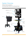
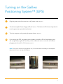
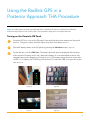
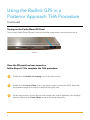
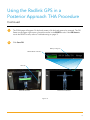
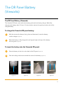
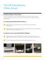
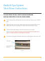
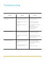
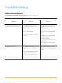
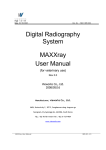
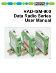
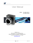
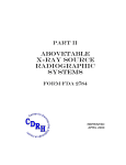
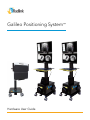
Galileo Positioning System™ Hardware User Guide System Overview Galileo Positioning System™ with Perkin Elmer Panel Or The Vieworks Panel Upper Monitor (shows pre-operative image) Lower Monitor (shows intra-operative image) DR Panel Keyboard Perkin Elmer Router Or Vieworks Control Box Battery charger Power Cord Reel Ethernet Cord Reel BNC Cord Reel (Connects to C-Arm Monitor) Computer Power Button Uninterruptable Power Supply (UPS) 1 Turning on the Galileo Positioning System™ (GPS) 1 Plug the power cord of the unit into an AC power outlet. (Figure 1) 2 The Uninterruptable Power Supply (UPS) will turn on. The leftmost UPS indicator light should now be green (see expanded view below). 3 Turn the computer on by pressing the power button. (Figure 2) 4 If you unplug the GPS, the system goes to battery mode (the UPS will start beeping and the orange battery light will illuminate), which enables the user to move the unit without plugging into the wall for 15 minutes. (Figure 3) Note: The unit can remained unplugged for only 15 minutes before the battery will be depleted. When the UPS is on, this light will be green. Figure 1 Figure 2 Figure 3 2 Using the Radlink GPS in an Anterior Approach THA Procedure 1 Pull the BNC cable from its cord reel and plug the cable into the Video Output Port on the back of the C-Arm monitor by pushing and twisting clockwise. 2 If images need to be pulled from PACS and WiFi access is not available, pull the Ethernet cable from its cord reel and plug into an Ethernet port. 3 Double-click the Radlink Pro Imaging icon on the lower monitor. 4 Double-click the Pre-op Viewer icon on the upper monitor to access the PACS. Select the pre-operative image to be used as a reference during the case. 5 On the lower monitor, click on the row for the study if the order is displayed in the modality worklist. Otherwise, click New Patient and enter the study information. 6 Once you are in QC Image page, click the Grab Frame tab. (Figure 4) 7 C-Arm images will appear at the bottom of the lower monitor screen. 8 Refer to the Surgeon’s Checklist™ user manual for instructions on how to take measurements with the software 9 10 3 Figure 4 If images need to be sent to PACS and WiFi access is not available, pull the Ethernet cable from its cord reel and plug into an Ethernet port. Once cases have been completed for the day, unplug the BNC cable from the back of the C-Arm monitor by pulling and twisting counter-clockwise. Gently pull on the BNC cable until it retracts. Using the Radlink GPS in a Posterior Approach THA Procedure Note: Your GPS system has been provided with either a Vieworks DR Panel or a Perkin Elmer DR Panel. Follow the steps below to turn on the panel. Then proceed to steps 4-13 to complete the case. Turning on the Vieworks DR Panel 1 Once the GPS is on, turn on the DR panel. Press and hold the power button until the panel turns on. The green, amber, and blue lights must all be illuminated. (Figure 5) 2 Check the battery status of the DR panel by pressing the Windows button. (Figure 6) 3 On the task bar, click the FMC icon. The battery level will then be displayed at the bottom of the window. If battery level is low, replace the battery. It is recommended to have a fully charged battery at the beginning of a case. (Figure 7) The battery charge shows in increments of 25%. (i.e. a battery with 75% charge will show as 75). Leave the FMC icon open during the case. (Figure 8) Figure 5 Figure 6 Figure 7 Figure 8 4 Using the Radlink GPS in a Posterior Approach THA Procedure Continued Turning on the Perkin Elmer DR Panel To turn on the Perkin Elmer DR panel, press and hold the power button until the panel turns on Figure 9 Once the DR panel has been turned on, follow Steps 4-13 to complete the THA procedure: 5 4 Double-click the Radlink Pro Imaging icon on the lower monitor. 5 Double-click the Pre-op Viewer icon on the upper monitor to access the PACS. Select the pre-operative image to be used as a reference during the case. 6 On the lower monitor, click on the row for the study if the order is displayed in the modality worklist. Otherwise, click New Patient and enter the study information. Using the Radlink GPS in a Posterior Approach THA Procedure Continued 7 The SCAN page will appear. On the body avatar, click the body part to be scanned. The DR Status on the upper right corner of screen must be in the READY mode. If the DR Status is not in the READY mode, refer to Troubleshooting on page 11. 8 Click Start DR. Battery Charge % READY Mode indicator Start DR Vieworks DR Panel Perkin Elmer DR Panel Figure 10 6 Using the Radlink GPS in a Posterior Approach THA Procedure Continued Important: Do not position the X-ray generator between the GPS and the DR Panel. Lead from the mobile X-ray can interfere with the wireless connection, resulting in the inability of the panel to acquire images. 9 Take the intraoperative X-ray. The image will appear on the lower monitor. 10 Use Image Orientation buttons to rotate the image. 11 Use the Image Appearance buttons to Window Level, Zoom in, etc. (Figure 11) 12 Refer to the Surgeon’s Checklist™ user manual to take measurements with the software. (Figure 12) 13 If it is necessary to shoot another image, click SCAN and Start DR and repeat steps 9-12. Figure 11 7 Figure 12 The DR Panel Battery (Vieworks) The DR Panel Battery (Vieworks) The Vieworks DR Panel comes with three battery packs and one battery charger. When fully charged, each battery lasts 2-3 hours. For best results, start each surgical procedure with a fully charged battery. To charge the Vieworks DR panel battery: 1 With the arrow at the bottom facing front and downward, insert the battery into the charger. (Figure 13) 2 When the battery is fully charged, the solid green light at the top of the battery will turn green. (Figure 14) To insert the battery into the Vieworks DR panel: 1 Place the battery in the slot on the back of the DR panel. (Figure 15) 2 Push the locking mechanisms toward the center of the battery. (Figure 16) Arrow Figure 13 Figure 14 Figure 15 Figure 16 8 The DR Panel Battery (Perkin Elmer) The DR Panel Battery (Perkin Elmer) The Perkin Elmer DR Panel comes with two battery packs and one battery charger. When fully charged, each battery lasts 2-3 hours. For best results, start each surgical procedure with a fully charged battery. To charge the Perkin Elmer DR Panel battery: 1 With the sticker at the bottom facing front and downward, insert the battery into the charger. (Figure 17) 2 When the battery is fully charged, the four solid green lights will be illuminated. If the battery is not fully charged, the lights will blink. (Figure 18) To insert the battery into the Perkin Elmer DR panel: 1 Place the battery in the slot on the DR panel. The sticker on the battery should be on the opposite side of the sticker on the panel. Insert the battery all the way untill it clicks. (Figure 19) 2 To remove the battery, push the knobs inward until the battery ejects. (Figure 20) Figure 17 9 Figure 18 Figure 19 Figure 20 Radlink Gps System Shut-Down Instructions TO SHUT DOWN THE GPS, THE FOLLOWING PROCEDURE MUST BE COMPLETED IN THE FOLLOWING ORDER: 1 Click the Windows icon in the lower left-hand corner of the lower monitor screen. Click Shut down. 2 Unplug the power cord from the AC power outlet. At this point, the Radlink GPS will go to battery mode. The solid orange light will illuminate and the UPS will begin to beep. 3 Press and hold the power button on the UPS to shut down the unit properly. Warning: If you do not shut the ups down by pressing and holding the power button (step 3), the battery will drain and will need to be replaced. 4 For a Posterior case, press and hold the power button on the DR panel in order to turn it off. Power Button Change Batter Mode Indicator Light Figure 21 10 Troubleshooting Problem Reason Solution Frame Grabber is not pulling images The video output at the back of the C-Arm Adjust/repair the video output port or try from the C-Arm monitor may be damaged or broken using a different C-Arm port. The signal mode on the Converter is not Press the Input button on the BNC set to BNC Converter to switch to BNC mode. Frame Grabber is not selected in the 1. Open the Radlink Pro Imaging software software and click “Manage”. 2. Make sure the Frame Grabber is checked under Hot Buttons. 3. Click Save Settings. Touch screen is not responding The user may be touching the inside of Press edges of the monitor frame to the monitor frame, blocking the sensors reconnect the touch screen sensors. The USB cable for the touch screen may Check the USB cable and make sure it is be loose firmly connected. If it is connected, unplug the cable and plug it back in. Computer response time is slow The computer may have been shut down Turn the computer on and let the using the power button rather than via computer reload until the Windows Windows home screen appears. This process may take several hours. Too many images from previous use are being stored on the computer 11 Call Radlink Technical Support. Troubleshooting Radlink Technical Support: For questions call Radlink Technical Support: 310-643-6900, ext. 2 Problem Reason Solution DR Status light reads “Initializing” instead The wireless communication between Make sure there is no lead (in the X-ray of “Ready”/DR Panel will not connect the panel and the router on the GPS is generator or lead gown) between the blocked or slow bucky and the GPS. DR Panel battery may be low Replace the battery with a fully charged battery. Unstable connection between DR panel and GPS 1. Close Radlink Pro Imaging software by clicking Manage Logout. 2. Turn off the DR Panel. 3. Turn on the DR Panel and wait until the LEDs stop flashing. 4. Launch Radlink Pro Imaging software. The GPS will not turn on The battery has been depleted because If the GPS is being used with the DR the GPS was not properly shut down Panel for posterior cases, call Radlink for a new UPS. If the GPS is only for anterior approach, call Radlink Technical Support for instructions on how to bypass the UPS. 12 Radlink Inc. www.radlink.com (310) 643-6900 815 N. Nash St. El Segundo, CA 90245