1
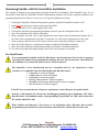
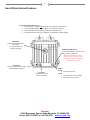
Table of Contents
Introduction ............................................................................................................................................................. 0
SmartWire Package Contents ................................................................................................................................. 1
Technical Specifications ......................................................................................................................................... 2
Becoming Familiar with the SmartWire Installation .............................................................................................. 3
Pre-Install notes: ................................................................................................................................................. 3
Example Installation Overview............................................................................................................................... 4
SmartWire External Features .................................................................................................................................. 6
SmartWire Mounting .............................................................................................................................................. 7
SmartWire Connections .......................................................................................................................................... 8
Power Supply: Main Stud ................................................................................................................................... 8
Ground Supply: Pin A19, A20, B19 ................................................................................................................... 8
Shutdown: Pin B20 ............................................................................................................................................. 8
Hardwired Direct Inputs ..................................................................................................................................... 9
Outputs ................................................................................................................................................................ 9
SmartWire 23 Pin Connector Pinout..................................................................................................................... 10
SmartWire Wiring................................................................................................................................................. 11
Datalink Wire Sizer App. (shown only in standalone applications) ................................................................ 12
Connector Requirements: 23 Pin Amp Connectors .......................................................................................... 13
Wire................................................................................................................................................................... 13
Wire Preparation ............................................................................................................................................... 13
Tooling .............................................................................................................................................................. 13
Socket Crimping ................................................................................................................................................... 14
Connector Assembly ............................................................................................................................................. 15
Connector Disassembly ........................................................................................................................................ 16
Seal Plug ............................................................................................................................................................... 16
External Devices ................................................................................................................................................... 17
Starter Solenoid ................................................................................................................................................. 17
Ignition .............................................................................................................................................................. 17
ECU or EFI ....................................................................................................................................................... 17
Solenoids ........................................................................................................................................................... 17
Windshield Wipers............................................................................................................................................ 18
Channel/Pin Chart ................................................................................................................................................. 20
Programming Manual Release A Dec0611
Disclaimer
Competition Systems Inc. Racepak make no representations or warranties of any type with respect to the
contents in this manual. Competition Systems Inc. Racepak disclaim any implied warranties or fitness for any
particular purpose. Competition Systems Inc. Racepak is not liable for any errors contained within or for
incidental or consequential damages in connection with the supply, performance or use of the hardware and
software or this manual.
Competition Systems Inc. Racepak reserve the right to revise this installation and user manual at any time,
without obligation to notify any person of revisions.
Warranty
Competition Systems Inc. Racepak make every effort to insure our products and services are of the highest
quality and standards. It is our intention to maintain a mutually beneficial and cordial relationship with each
and every customer.
Competition Systems Inc. Racepak warrants all merchandise manufactured by Competition Systems Inc.
Racepak against defects in workmanship or material for a period of six months after the data of purchase. This
warranty applies to the first retail purchaser and covers only those products exposed to normal use or service. It
does not apply to those products used for a purpose for which said products were not designed, or which has
been altered in any way that would be detrimental to the performance or life of the product, or misapplication,
misuse, negligence, or accident. Any part or product found to be defective after examination by Competition
Systems Inc. Racepak will be repaired or replaced. Competition Systems Inc. Racepak assumes no
responsibility for diagnosis, removal and/or installation labor, loss of vehicle use, loss of time, inconvenience or
any other consequential expenses.
This warranty is in lieu of any other expressed or implied warranties, including any implied warranty or
merchantability or fitness, and any other obligation on the part of Competition Systems Inc. Racepak, or selling
dealer.
If you have any questions regarding warranty, please contact customer service at Competition Systems Inc.
Racepak. 949-709-5555
Introduction
Solving the wiring complexity of a modern race car, the Racepak SmartWire is a fully programmable power
control module. While traditional wiring provides control of vehicle electronic components through the routing
of single, or multi-fuse, relay, and circuit breaker panels, the Racepak SmartWire functions as a central
“command center” for all vehicle wiring.
Based on Racepak’s exclusive single cable V-Net technology, the Racepak SmartWire unit is the electronic
“starting point”, with a direct main power connection from the vehicle battery to the SmartWire unit. Each
output is user defined, both in function, current requirement and current limit via a USB connection to the user’s
PC. The design of the SmartWire unit will reduce overall installation weight / clutter, while contributing to a
quicker reacting electronic system, through the solid state switching design.
Manual activation can be achieved through the 12 hardwired direct inputs on the SmartWire unit, or through the
use of the optional Racepak SwitchPanel or SwitchModule units. When utilized, a single small cable is routed
to the SwitchPanel/SmartModule from the Racepak SmartWire unit, reducing wiring clutter. Users needing
additional switch panel capabilities can easily expand through the use of an additional “jumper” cable to a
second Racepak SwitchPanel/SmartModule.
The Racepak V-Net compatibility of the SmartWire unit insures a seamless integration with existing Racepak
V-Net equipped vehicles. When connected with existing V-Net equipment, these items provide additional
inputs, control modules and instrumentation, compared to when utilized as a standalone power control module.
This manual will guide by step through the installation, setup, and operation of the SmartWire unit. During this
process, the manual may refer to system worksheets and individual instruction sheets originally provided with
other Racepak sensor modules and devices.
To get the most out of the Racepak SmartWire unit, it is highly recommended to thoroughly read the
entire manual before installation and use of the Racepak SmartWire unit. In addition, test the
SmartWire unit and settings/functions before use. The race track is not the place to determine something
is not working properly!
1
SmartWire Package Contents
•
•
•
•
SmartWire main unit
Connector kit
USB programming Cable
Programming Software
Racepak
30402 Esperanza, Rancho Santa Margarita, CA 92688 USA
Phone: 949-709-5555 Fax: 949-709-5556 www.racepak.com
2
Technical Specifications
Output Capacity:
Current Consumption:
Min/Max Power Supply:
Operating Power Supply:
Inputs:
Outputs:
Response:
Programming:
Dimensions:
Weight:
125 Amps
180 mA typical operation (<1 mA in shutdown mode)
8-20 Volts
12-16 volt automotive applications.
12 hardwired direct (voltage triggered (>2.7V) or ground triggered (<2.5V)
30 (8 outputs @ 20 Amps, 22 outputs @ 10Amps)
3.0 milliseconds max.
USB (or via V-Net when used with a V-Net data recorder)
Length 6.5” (16.51 cm), Width 5.5” (13.97 cm), Height 2.0” (5.08 cm)
25.8 ounces (731.4 grams)
Note: All current ratings are for 12 volt operation. For 16 volt systems, subtract 25 percent.
Connections:
•
•
•
•
•
Two - 23 pin Ampseal, (hardwired direct inputs, outputs, grounds and shutdown pin)
One - 1/4”x 20 Main Stud, (main power supply)
One USB mini (programming when utilized without a compatible data recorder)
One Switch CAN bus (connection for optional Switch Panel and/or Switch Module)
One V-Net CAN bus (connection for optional V-Net sensors and/or compatible data recorders)
Outputs are:
•
•
•
•
•
•
Monitored for Current, Voltage, and Status
Protected via user settable limits for over-current situations
Protected from short circuits and/or thermal overload situations
Function programmable as:
o Constant On
o Flash
o Latch On
o Single Pulse
o Windshield Wiper (only available on channel 19)
Time Delayed for On or Off
Outputs are controlled via any combinations of:
o Switchable inputs
o Programmed logic operations;
(Equal to, Not Equal to, Greater than, Greater than or Equal to, Less than, Less than or
Not Equal to)
o V-Net attached sensors (Temperatures, Pressures, RPM, etc.)
o Other Outputs
Racepak
30402 Esperanza, Rancho Santa Margarita, CA 92688 USA
Phone: 949-709-5555 Fax: 949-709-5556 www.racepak.com
3
Becoming Familiar with the SmartWire Installation
This manual is designed to provide guidance through the hardware installation of the SmartWire unit. Use of
this manual, along with the SmartWire Software/Programming manual, will provide complete installation and
programming instructions. Below is an overview of a typical installation and setup.
1.
2.
3.
4.
5.
6.
Utilizing the SmartWire Software/Programming manual, install the DatalinkII software on PC
Install only the main power and grounds on the SmartWire
Connect SmartWire to PC using supplied USB cable
Utilizing the SmartWire Programming Installation manual, open the configuration file on PC
Sync the configuration file with the SmartWire
Name, program, and send each of input (Hardwired direct inputs). Smart Panel/Smart Module and VNet items can be programmed at this time if connected. Or, each can be programmed at a later date.
7. Name, program, and send each of the outputs (ensure correct Amperage rating for each device)
8. Wire each of the inputs per programmed settings (see Hardware Installation Manual)
9. Wire each of the outputs per programmed settings (see Hardware Installation Manual)
10. Test each of the input and output settings. Insure each circuit operates as intended
Pre-Install notes:
It is recommended to initially install the Main Power and Ground wires first in order to program
each input and output. Once programmed, terminate and wire only the necessary connections. Do
not terminate every connection, unless a device will be connected.
The SmartWire can be installed and used as a standalone unit (i.e. not connected to a data
recorder) or is compatible with the following Racepak Data Recorders:
•
•
•
•
•
•
V300 (firmware version 41 or higher)
V300SD (firmware version 22 or higher)
V500 (firmware version 56 or higher)
IQ3 Logger Dash (firmware version 15 or higher)
IQ3 Display Only non-logger Dash (firmware version 17 or higher)
G2X Pro (firmware version 57 or higher)
If the PC does not meet the above firmware requirement, contact Racepak for update details.
Portions of this manual will call out two installing/programming types; Standalone AND with a
Data Recorder. In Standalone mode, all programming is performed via USB cable between the
PC and the SmartWire unit.
When utilized with Racepak V-Net sensors or in conjunction with a Racepak data recorder,
programming is performed via serial connection between the PC and the data recorder unit.
Racepak
30402 Esperanza, Rancho Santa Margarita, CA 92688 USA
Phone: 949-709-5555 Fax: 949-709-5556 www.racepak.com
4
Example Installation Overview
In a standard switch/device application, power is routed to a switch, with this switch controlling one device.
Depending on the device current (Amperage) requirement, this switch controls a relay, when triggered, allows a
large amount of current flow to the device. Activating the device requires manually flipping a switch.
Standard switch installation:
Two Switches:
One for Water Pump
One for Fan
Fuse
One switch for each device.
Fuse
M
Switch
Water Pump
Switch
Switch on, device on.
Relay
Fan
Battery
Basic SmartWire installation
One switch for each device.
Switch on, device on.
Monitors on both devices for:
• Current (Amps)
• Voltage
• Status (on/off/blown fuse)
M
SmartWire
Unit
Two Switches:
One for Water Pump
One for Fan
Hardwired
Inputs
Outputs
Water Pump
Battery Input
Fan
Battery
Option #1 SmartWire installation
Switch on, both devices on.
Hardwired
Input
Fan
Battery
V-Net to
SmartWire
Tee
One switch for manual override, V-Net sensor used
for trigger
V-Net Input
V-Net Port
Switch on, devices on regardless of temperature
input.
Water
Temp
Module & Sensor
SmartWire
Unit
One Switch for both:
Force both on
M
Outputs
Hardwired
Input
Sensor failure, SmartWire can be programmed to
force devices on should temperature go outside
sensor readable scale regardless of switch position.
Monitors both outputs/devices for:
• Current (Amps)
• Voltage
• Status (on/off/blown fuse)
Water Pump
Battery Input
Option #2 SmartWire installation
Switch off; SmartWire is programmed to
automatically turn both devices on at user set
temperatures based on V-Net input. SmartWire can
toggle both devices on/off at set timer intervals
Outputs
One Switch for both
SmartWire can toggle both devices on/off at
set timer intervals
Monitors both devices for:
• Current (Amps)
• Voltage
• Status (on/off/blown fuse)
M
SmartWire
Unit
One switch for both devices.
Water Pump
Battery Input
Fan
Battery
Racepak
30402 Esperanza, Rancho Santa Margarita, CA 92688 USA
Phone: 949-709-5555 Fax: 949-709-5556 www.racepak.com
5
Option #3 SmartWire installation in conjunction with Racepak V-Net data recorder
When connected to a V-Net data recorder, each sensor can be utilized for on/off function or logic control of
each device connected to the SmartWire. Optional Racepak Switch Panels or Switch Modules can also added
and connected to the SmartWire for more inputs and/or control.
Optional Switch Panel
Fuel Pump
To Display
Dash
Voltage triggered switches
Sensor
Input
To Data
Recorder
Sensor
Input
M
M
Optional
Switch
Module
Water pump
Fan
Ground triggered
switches
Optional
V-Net
Inputs
Optional Switch
Panel Inputs
Switch port
Ground
triggered
Switches
V-Net port
Solenoids
SmartWire
Unit
Outputs to
additional
devices
Outputs
Hardwired Inputs
Voltage
triggered
Switches
Battery Input
Main stud
Ground
(3 wires)
Lights
Starter
Solenoid
Starter
Cut-Off
Switch
Ignition
ECU
Main Power from Battery
or cut-off switch
Battery
Alt
V-Net Data
Recorder
Note: Most ignition and ECU systems require a direct main power connection.
This main power connection must go directly to the battery. DO NOT connect
the main power wire from these devices to the SmartWire outputs. Each of
these devices will also have a small wire requiring an ignition switched power
source. This small wire will connect to an output from the SmartWire.
Racepak
30402 Esperanza, Rancho Santa Margarita, CA 92688 USA
Phone: 949-709-5555 Fax: 949-709-5556 www.racepak.com
6
SmartWire External Features
Two 23 Pin Amp connectors for:
• Thirty Outputs: Output to all vehicle devices requiring switched power
• Twelve Hardwired Direct Inputs: Inputs from switches and buttons
• Three SmartWire Ground: Main grounding for SmartWire unit
• One Shutdown Pin: Main power shutdown for SmartWire when grounded
Main Stud:
Main power for SmartWire
from battery
11.5 volts minimum for
typically operating
USB Programming Port:
Used for programming when no V-Net
data recorder is connected.
Note: Not used when SmartWire is
utilized with a V-Net Data recorder.
Programming will then be performed
through the data recorder.
Switch Port:
Connection for External Switch
Panels/Modules if utilized
V-Net Port:
Connection for V-Net
devices if utilized
Lights:
Power:
• Red when powered
Status:
• Green when no fuses are blown
• Red when a fuse is blown
Racepak
30402 Esperanza, Rancho Santa Margarita, CA 92688 USA
Phone: 949-709-5555 Fax: 949-709-5556 www.racepak.com
7
SmartWire Mounting
The most important consideration, when mounting the SmartWire unit, is selecting the proper location. Several
issues were covered in the previous section regarding installation. The following additional requirements
should be taken into consideration.
1. Choose a mounting location that allows easy access to the USB port and the main 23 pin wire
connectors.
2. Avoid mounting the SmartWire directly on or near a heat source, on the floor near the exhaust system,
under the hood, etc.
3. Avoid mounting the SmartWire unit directly near the ignition box or any other electronic ignition
components. Maintain a minimum of 18 inches of clearance between the SmartWire unit and any of
these type items.
4. Choose a location that will allow easy routing of the interconnecting cables. Care must be taken to
prevent the cables from interfering with the driver, safe operation of the vehicle, any maintenance, or
repair services.
5. Always mount the SmartWire using the four rubber shock isolators “feet” provided. This will protect the
unit from shock and vibration damage.
6. Temperature. The internal temperature should be checked to ensure no more than a 50 °F difference
between ambient and internal. Internal SmartWire unit temperature can be viewed in the DatalinkII
software while connected to the PC.
Mounting hole size: .1875” / .476 cm. The mount feet locations and correct positioning are shown above.
Racepak
30402 Esperanza, Rancho Santa Margarita, CA 92688 USA
Phone: 949-709-5555 Fax: 949-709-5556 www.racepak.com
8
SmartWire Connections
Before terminating the 23 pin connectors, it is highly recommended that the DatalinkII software be installed and
the SmartWire outputs are programmed. This will dictate which output connections will be utilized. Do not
insert every socket in the connector unless a device will be connected. See SmartWire Programming Manual
for details.
Power Supply: Main Stud
Power is supplied to the SmartWire unit using the main Battery + ¼” stud on the unit. The main power stud will
be connected direct to the positive terminal on the battery. In situations where a main power cut-off switch is
required, the SmartWire main power should connect to switched side of the cut-off switch to ensure power is
removed from battery as per the rules.
Wire gauge to be based on maximum wire temperature and the accepted voltage drop for the application. (See
wiring section)
NOTE: The SmartWire is designed as a switching control unit. The SmartWire unit is not
designed as a main power feed for certain high current items. These items include, but not limited
to ignition and electronic fuel systems. Refer to device manual for power requirements.
If the manufacturer recommends the main power be connected to the main direct battery power,
follow the manufacturer’s requirement and DO NOT connect items through the SmartWire.
Ground Supply: Pin A19, A20, B19
A grounding path is supplied by the SmartWire unit using three individual terminals on the two main
connectors. Pins A19, A20, and B19 must be securely connected to the battery negative terminal or to a secure
chassis ground. Since each switched device connected to the SmartWire outputs will have its own ground path,
the three connections will carry a low amount of current. Each ground requires a minimum 18 gauge wire.
DO NOT connect the three wires together and run a single wire to ground. Three separate, correctly sized
wires need to be connected to the battery negative post.
Shutdown: Pin B20
A master shutdown is incorporated into the SmartWire unit, which enables complete power cut off to both the
main unit and all outputs. When pin B20 is grounded, all power between the main stud and the SmartWire will
be completely terminated/disabled. When this function is enabled, the SmartWire unit will draw less than 1
Milliamp of current. The SmartWire unit retains all program settings during this off period. Once ground is
removed from this pin, the unit will resume normal operation.
Racepak
30402 Esperanza, Rancho Santa Margarita, CA 92688 USA
Phone: 949-709-5555 Fax: 949-709-5556 www.racepak.com
9
Hardwired Direct Inputs
The SmartWire unit contains 12 pins for direct switch inputs. Using the DatalinkII software, each input can be
programmed to accept a voltage triggered input or a ground triggered input.
The trigger levels are:
• Ground Trigger: Input is triggered/active when the pin/connection is grounded. (From open to a
ground or from a voltage to ground)
• Voltage Trigger: Input is triggered/active when the pin/connection has voltage* applied. (From
open to voltage or from a ground to voltage), minimum 4 volts required.
* Minimum trigger voltage requirement: 4 Volts. Voltages higher than 19.5 are not recommended.
Wire size: 20 gauge wire, as switch inputs do not require a large amount of current.
Outputs
The SmartWire unit contains a total of 30 pins for output switching.
• 8 channels at 20 amp maximum
• 22 channels at 10 amp maximum
Each output is switched to battery power when its channel parameters are activated. All channels have
programmable logic control, current limiting and overload protection settings.
Output channels can be wired in parallel to increase current but must be of same type:
2 x 20Amp =40 Amp (two 20Amp outputs to create a single 40Amp output)
or
2 x 10 Amp = 20 Amp (two 10Amp outputs to create a single 20Amp output)
When output channels are wired in parallel, special channel logic is required.
DO NOT wire channels of different output together (i.e. do not connect a 20Amp
with a 10Amp output).
When connecting to devices, if the manufacturer of the device recommends the main
power be connected to the main direct battery power, follow the manufacturer’s
requirement and DO NOT connect items through the SmartWire.
Racepak
30402 Esperanza, Rancho Santa Margarita, CA 92688 USA
Phone: 949-709-5555 Fax: 949-709-5556 www.racepak.com
10
SmartWire 23 Pin Connector Pinout
Pin numbers are located on wire connector.
SmartWire unit is labeled A or B above each port.
Table 1 - Input Pins (hardwired direct)
"A" Connector
PIN#
10
11
12
13
14
18
"B" Connector
Input
Channel#
1
3
4
5
6
2
Input
Channel#
7
8
9
10
11
12
PIN#
10
11
12
13
14
18
Defaulted Channel name in
software shown below
Table 2 - 20 Amp Output pins
"A" Connector
PIN#
1
3
6
8
"B" Connector
Output AMP
Channel#
4
20
1
20
2
20
3
20
PIN#
1
3
6
8
Output AMP
Channel#
5
20
7
20
8
20
6
20
Defaulted Channel names in
software shown below
Table 3 - 10 Amp Output pins
"A" Connector
PIN#
2
4
5
7
9
15
16
17
21
22
23
Output
Channel#
10
11
13
15
12
20
9
19
14
16
17
"B" Connector
AMP
PIN#
10
10
10
10
10
10
10
10
10
10
10
2
4
5
7
9
15
16
17
21
22
23
Output AMP
Channel#
22
10
28
10
25
10
26
10
21
10
27
10
18
10
24
10
23
10
29
10
30
10
Defaulted Channel name in
software shown below
Table 4 - Other
"A" Connector
"B" Connector
PIN#
19
Function
Ground
PIN#
19
Function
Ground
20
Ground
20
Shutdown
Racepak
30402 Esperanza, Rancho Santa Margarita, CA 92688 USA
Phone: 949-709-5555 Fax: 949-709-5556 www.racepak.com
11
SmartWire Wiring
The SmartWire unit is equipped with socket terminals and main connectors for the end user to assemble the
harness connection to the main unit. Typical harness wire gauge will be 16-24 AWG.
When wiring the SmartWire unit, utilize the proper wire type for the application. Wire is rated both on current
and temperature. Verify both the correct wire size and casings/insulation, based on current draw and location of
wiring, in the vehicle.
Below are common wire types:
• GPT wire (SAE J1128-GPT)
• SXL (SAE J1128-SXL)
• GXL (SAE J1128-GXL)
• TXL (SAE J1128-TXL)
• ETFE - (TEFZEL) MIL22579
• PTFE - (TEFLON) MIL22579
Teflon and/or Tefzel are the preferred wire type for automotive application. Higher quality Teflon or Tefzel
wire utilize silver plated conductors.
General wire selection guidelines:
• The smaller the wire diameter, the greater the resistance and thus lower current capability over a given
length. In most cases, larger gauge wire can be utilized. When in doubt, as the load increases, so should
the wire gauge (larger wire).
• Other factors can affect the load capacity of wire, besides length
o Environment Temperature
o Duration of load
o Stranded vs. Solid wire
o Wire plating.
• Higher capacity wiring utilizes silver plating with a higher strand count and as such will typically have a
higher capacity, when compared to copper stranded wires.
The actual maximum current capacity rating of a particular wire size is affected by the operating temperature of
the wire. Wire gauge should be chosen according to the wire temperature limit and acceptable voltage drop. In
most instances, a 3% voltage drop is the recommended limit. The temperature of the wire is affected by the
ambient temperature, air circulation, current, wire gauge, the temperature of any surrounding wires and the
covering sheath. Wire gauge is based on maximum wire temperature and the accepted voltage drop for the
application.
Racepak
30402 Esperanza, Rancho Santa Margarita, CA 92688 USA
Phone: 949-709-5555 Fax: 949-709-5556 www.racepak.com
12
As a general rule, the following charts can be utilized. Shown values are the maximum recommended length in
feet, for each wire size at the shown current (Amps). When planning for both, power and ground, make sure the
wire will support the total calculated length of both runs.
Max run in feet at 12 volts with a max 3% voltage drop @ 25C (77F)
Current (Amperage)
AWG
3
5
7.5
10
15
22
7.4
4.5
3.0
2.2
1.5
20
11.8
7.1
4.7
3.5
2.4
18
18.8
11.3
7.5
5.6
3.8
16
29.9
17.9
12.0
9.0
6.0
14
47.5
28.5
19.0
14.3
9.5
12
75.6
45.3
30.2
22.7
15.1
10
120.1
72.1
48.1
36.0
24.0
20
1.1
1.8
2.8
4.5
7.1
11.3
18.0
Max run in feet at 12 volts with a max 3% voltage drop @ 100C (212F)
Current (Amperage)
AWG
3
5
7.5
10
15
20
5.1
3.1
2.1
1.5
1.0
0.8
22
8.2
4.9
3.3
2.4
1.6
1.2
20
12.9
7.8
5.2
3.9
2.6
1.9
18
20.6
12.4
8.2
6.2
4.1
3.1
16
32.8
19.7
13.1
9.8
6.6
4.9
14
52.1
31.3
20.8
15.6
10.4
7.8
12
82.9
49.7
33.1
24.9
16.6
12.4
10
Datalink Wire Sizer App. (shown only in standalone applications)
To aid in selecting the correct wire gauge, the SmartWire configuration file contains a wire sizer app.
If you haven’t done so yet, install the Datalink software. The wire sizer app is located in the Run Log area.
This can be found by opening the Datalink programSelectingFileOpen Car Configuration
SmartWireClick OKViewOrganize PanesLocate SmartWire Plug Wire Sizer across the bottom of
the window.
Racepak
30402 Esperanza, Rancho Santa Margarita, CA 92688 USA
Phone: 949-709-5555 Fax: 949-709-5556 www.racepak.com
13
Connector Requirements: 23 Pin Amp Connectors
Wire
Wire Selection
The socket will accept wire ranging in size from 20 to 16 AWG and 1.5 mm. Wire insulation diameter should
be a minimum 1.7 mm, maximum 2.7mm. Smaller wire gauge can be used but will require careful preparation
to correctly fit during the crimping process.
Wire Preparation
Wire should be stripped approximately .2” (5.1mm). Care should be taken during the stripping process to ensure
the wire (conductor) is not nicked, scraped, or cut.
Tooling
The appropriate crimp pliers must be used to ensure a proper secure crimp designed for the 23 pin AMP
connector.
Below are the part numbers for the correct crimper tool:
Racepak:
Tyco:
# 800-XP-CRIMPAMP
# 58529-1
Racepak AMP Automotive Crimp Tool
PRO-CRIMPER III Hand Tool with Die Assembly #58529-2
Extra SmartWire connector and pins are available for purchase.
Racepak:
# 810-CN-AMP23
(1 connectors and 25 sockets)
The ends of the insulation barrel shall be wrapped around the wire insulation, leaving no sharp
points to damage the rubber wire seal.
Racepak
30402 Esperanza, Rancho Santa Margarita, CA 92688 USA
Phone: 949-709-5555 Fax: 949-709-5556 www.racepak.com
14
Socket Crimping
The sockets should be crimped and then inspected for conditions shown below:
Proper Crimping on wire insulation required for socket to insert correctly.
Incorrect
End should be completely
round
Correct
Completely round
NOTE: Wire stripping tool jaws may leave corrugated indentations on the surface of the wire
insulation. This is especially severe with cross-linked polyethylene (high temperature) insulation. If
these indentations occur at the location of the wire seal, leakage may result. Insulation surface within 26
mm from the tip of the contact must be smooth and free of residual indentations.
Care should be taken to ensure that the wire insulation is not cut or broken during the crimping
operation, and to ensure that the insulation is not crimped into the wire barrel.
The ends of the insulation barrel shall be wrapped around the wire insulation, leaving no sharp points to
damage the rubber wire seal.
Racepak
30402 Esperanza, Rancho Santa Margarita, CA 92688 USA
Phone: 949-709-5555 Fax: 949-709-5556 www.racepak.com
15
Connector Assembly
1. Verify the wedge lock is in the open position (shown above).
2. Insert socket and push in straight into the selected circuit cavity as far as it will go (shown below)
3. Gently pull back on socket/wire to be sure the retention fingers are holding the socket
4. After all wire/sockets have been inserted, the wedge lock must be closed to its locked position.
5. Release the locking latches by squeezing them inward (shown below)
6. Slide the wedge lock into the housing until it is flush with the housing (shown below)
Racepak
30402 Esperanza, Rancho Santa Margarita, CA 92688 USA
Phone: 949-709-5555 Fax: 949-709-5556 www.racepak.com
16
Connector Disassembly
1. Do not damage the connector during disassembly. As shown below, insert small screw driver between
mating seal and one of the red wedge lock tabs.
2. Gently pry open the wedge lock to the open position.
3. While rotating the wire back and forth (at least a 1/4 turn in each direction), gently pull the wire until the
wire/socket is removed.
NOTE: The wedge lock should never be removed from the housing for insertion or removal of the sockets.
Seal Plug
All circuits are sealed by a diaphragm in the rubber wire seal. During plug connector assembly, the diaphragm
is pierced as the contact passes through it. Unused circuit cavities, unless accidentally perforated, will remain
sealed. A seal plug is available and designed to keep out contaminant if the diaphragm is pierced.
To install seal plug, insert seal plug large end first, into circuit cavity as far as it will go. An insertion tool is not
required. (See below)
Racepak
30402 Esperanza, Rancho Santa Margarita, CA 92688 USA
Phone: 949-709-5555 Fax: 949-709-5556 www.racepak.com
17
External Devices
Starter Solenoid
The starter solenoid in most cases will require a 20 Amp output. In some cases, the starter solenoid can draw
greater than 20 Amps, especially during extended cranking periods. Due to the SmartWire design, the output
current can exceed the current fuse limitation for short periods of time (typically <4 seconds). Should the
current exceed the fuse setting for extended periods (i.e. more than 5-10 seconds) the output will be deactivated.
A re-try setting is available for both time and number of retries (see programming manual for further details).
Ignition
Most ignition systems have two power inputs. One is a main power feed for the system (normally accompanied
with a main ground feed) and the other is a switched power designed for an ignition switched power source. The
SmartWire unit is not designed as a main power feed for the ignition unit. The SmartWire is designed as a
switching control unit, the main power and ground wires from the ignition system should connect directly to the
battery and ground.
ECU or EFI
Most engine management or electronic fuel injection systems have two power inputs. One is a main power feed
for the system (normally accompanied with a main ground feed) and the other is a switched power designed for
an ignition switched power source. The SmartWire unit is not designed as a main power feed for the fuel
injection system. Since the SmartWire is designed as a switching control unit, the main power and ground wires
from the ignition system should connect directly to the battery and ground.
Solenoids
When connecting the SmartWire to solenoids for items such as trans-brake. nitrous, water injection, etc., insure
the current draw of the solenoid does not exceed the maximum rating for the output.
When connecting to devices, if the manufacturer of the device recommends the main power be
connected to the main direct battery power, follow the manufacturer’s requirement and DO NOT
connect items through the SmartWire.
Racepak
30402 Esperanza, Rancho Santa Margarita, CA 92688 USA
Phone: 949-709-5555 Fax: 949-709-5556 www.racepak.com
18
Windshield Wipers
The SmartWire unit can operate windshield wiper motors within the following guidelines:
Most wiper motors have multiple speeds, slow and fast. The SmartWire cannot be connected to both fast and
slow terminals at the same time due to voltage being generated by the internal windings of the wiper motor
during operation.
NOTE: The following methods are for ‘common-ground’ wiper assemblies. For ‘common-positive’
wiper assemblies, the methods would need to be adjusted accordingly.
1. Utilizing the factory OEM controller
The below method utilizes the vehicles factory wiper controller. The SmartWire is used to supply power
only to the factory controller. The controller handles all wiper motor functions such as the intermittent
and motor braking.
SmartWire
S
Output
Wiper
Motor
F
Factory
Controller
Factory
Control
Switches
Home
Park
Switch
2. Utilizing two switches, one output
Below method uses two external switches.
• One switch for supplying power to the wiper motor,
• One switch used to toggle the wiper speed.
The SmartWire supplies only the power. The braking function for the wiper motor is handled between the use
of the power switch and the internal park switch. Intermittent operation cannot be done since a single power
supply is used. Removal of this power source (instead of using the on/off switch) will cause the wipers not to
park in the correct position.
Output
On
SmartWire
On/Off
Switch
Slow
S
Off
Speed
Switch
Wiper
Motor
F
Fast
Home
Park
Switch
Racepak
30402 Esperanza, Rancho Santa Margarita, CA 92688 USA
Phone: 949-709-5555 Fax: 949-709-5556 www.racepak.com
19
3. Utilizing a relay, two outputs
Below method uses a single external switch and a relay. This method provides the ability for intermittent
operation.
Two SmartWire outputs are required for this method.
• One output controls a relay for intermittent operation
• One output supplies power through the same relay for the main wiper motor power
The braking function for the wiper motor is handled between the use of the power relay and the internal park
switch. Intermittent function is controlled by turning the relay off momentary. The delay time setting can be
determined by the end user and programmed on the output controlling the relay. The other output is the main
power feed for the motor. When the relay is energized, the power is fed to the motor via direct or through the
speed switch. When the relay is de-energized, power is fed through the park switch to the relay and then to the
motor via direct or through the speed switch. When the Park switch is on, power will continue to the Relay.
When the park switch is off, power is cutoff to the motor.
Relay
Output
Slow
SmartWire
On
Wiper
Motor
S
Output
Off
F
Fast
Home
Park
Switch
4. Direct (Only available on output channel 19), one output, one input
When a direct method is required, a reference channel must be selected in order to Park the wipers in the correct
location. Output channel 19 (pin A17) has this ability when its Output Function is configured for Windshield
Wiper. This method is only available on output channel 19 (pin A17).
When set to this, a Wiper Brake Control Channel becomes selectable. This is the channel that will be referenced
for the Park position. Any input can be used, although we will describe the use of a hardwired direct input.
Connect the Park switch as shown below. The input channel settings need to be set appropriately (ground
triggered as shown below). When the Park switch is in the home position, the input channel will be grounded.
This will make the input channel true, causing the wiper motor to stop. Other inputs channels can be selected
for use. The input can be either a hardwired direct input or a V-Net sensor input (not requiring the use of the
hardwired direct input).
Slow
Output
S
SmartWire
F
Wiper
Motor
Fast
Input
Home
Park
Switch
Racepak
30402 Esperanza, Rancho Santa Margarita, CA 92688 USA
Phone: 949-709-5555 Fax: 949-709-5556 www.racepak.com
20
Channel/Pin Chart
Sorted by Pin Number
"A" Connector
PIN
CH#
Type
A1
A2
A3
A4
A5
A6
A7
A8
A9
A10
A11
A12
A13
A14
A15
A16
A17
A18
A19
A20
A21
A22
A23
PIN
"B" Connector
CH#
Type
4
Output
20
B1
5
Output
10
Output
10
B2
22
Output
1
Output
20
B3
7
Output
11
Output
10
B4
28
Output
13
Output
10
B5
25
Output
2
Output
20
B6
8
Output
15
Output
10
B7
26
Output
3
Output
20
B8
6
Output
12
Output
10
B9
21
Output
1
Input
B10
7
Input
3
Input
B11
8
Input
4
Input
B12
9
Input
5
Input
B13
10
Input
6
Input
B14
11
Input
20
Output
10
B15
27
Output
9
Output
10
B16
18
Output
19
Output
10
B17
24
Output
2
Input
B18
12
Input
NA
ground
B19
NA
Ground
NA
ground
*B20
On/Off
Shutdown*
14
Output
10
B21
23
Output
16
Output
10
B22
29
Output
17
Output
10
B23
30
Output
*Grounding the Shutdown pin will turn off power to the SmartWire unit and all outputs.
Sorted by Channel Number
"A" Connector
CH#
Type
PIN
1
1
2
2
3
3
4
4
5
6
9
10
11
12
13
14
15
16
17
19
20
NA
NA
AMP
AMP
CH#
"B" Connector
Type
PIN
Output
A3
20
5
Output
B1
Input
A10
6
Output
B8
Output
A6
20
7
Output
B3
Input
A18
7
Input
B10
Output
A8
20
8
Output
B6
Input
A11
8
Input
B11
Output
A1
20
9
Input
B12
Input
A12
10
Input
B13
Input
A13
11
Input
B14
Input
A14
12
Input
B18
Output
A16
10
18
Output
B16
Output
A2
10
21
Output
B9
Output
A4
10
22
Output
B2
Output
A9
10
23
Output
B21
Output
A5
10
24
Output
B17
Output
A21
10
25
Output
B5
Output
A7
10
26
Output
B7
Output
A22
10
27
Output
B15
Output
A23
10
28
Output
B4
Output
A17
10
29
Output
B22
Output
A15
10
30
Output
B23
ground
A19
NA
Ground
B19
ground
A20
On/Off
Shutdown*
*B20
*Grounding the Shutdown pin will turn off power to the SmartWire unit and all outputs.
Racepak
30402 Esperanza, Rancho Santa Margarita, CA 92688 USA
Phone: 949-709-5555 Fax: 949-709-5556 www.racepak.com
AMP
20
10
20
10
10
20
10
20
10
10
10
10
10
10
10
AMP
20
20
20
20
10
10
10
10
10
10
10
10
10
10
10