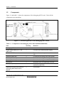
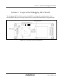
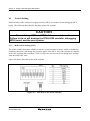
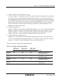
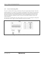
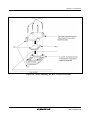
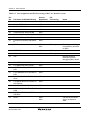
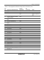
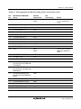
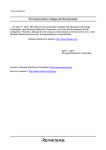
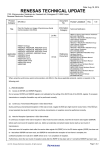
1
To our customers,
Old Company Name in Catalogs and Other Documents
On April 1st, 2010, NEC Electronics Corporation merged with Renesas Technology
Corporation, and Renesas Electronics Corporation took over all the business of both
companies. Therefore, although the old company name remains in this document, it is a valid
Renesas Electronics document. We appreciate your understanding.
Renesas Electronics website: http://www.renesas.com
April 1st, 2010
Renesas Electronics Corporation
Issued by: Renesas Electronics Corporation (http://www.renesas.com)
Send any inquiries to http://www.renesas.com/inquiry.
Notice
1.
2.
3.
4.
5.
6.
7.
All information included in this document is current as of the date this document is issued. Such information, however, is
subject to change without any prior notice. Before purchasing or using any Renesas Electronics products listed herein, please
confirm the latest product information with a Renesas Electronics sales office. Also, please pay regular and careful attention to
additional and different information to be disclosed by Renesas Electronics such as that disclosed through our website.
Renesas Electronics does not assume any liability for infringement of patents, copyrights, or other intellectual property rights
of third parties by or arising from the use of Renesas Electronics products or technical information described in this document.
No license, express, implied or otherwise, is granted hereby under any patents, copyrights or other intellectual property rights
of Renesas Electronics or others.
You should not alter, modify, copy, or otherwise misappropriate any Renesas Electronics product, whether in whole or in part.
Descriptions of circuits, software and other related information in this document are provided only to illustrate the operation of
semiconductor products and application examples. You are fully responsible for the incorporation of these circuits, software,
and information in the design of your equipment. Renesas Electronics assumes no responsibility for any losses incurred by
you or third parties arising from the use of these circuits, software, or information.
When exporting the products or technology described in this document, you should comply with the applicable export control
laws and regulations and follow the procedures required by such laws and regulations. You should not use Renesas
Electronics products or the technology described in this document for any purpose relating to military applications or use by
the military, including but not limited to the development of weapons of mass destruction. Renesas Electronics products and
technology may not be used for or incorporated into any products or systems whose manufacture, use, or sale is prohibited
under any applicable domestic or foreign laws or regulations.
Renesas Electronics has used reasonable care in preparing the information included in this document, but Renesas Electronics
does not warrant that such information is error free. Renesas Electronics assumes no liability whatsoever for any damages
incurred by you resulting from errors in or omissions from the information included herein.
Renesas Electronics products are classified according to the following three quality grades: “Standard”, “High Quality”, and
“Specific”. The recommended applications for each Renesas Electronics product depends on the product’s quality grade, as
indicated below. You must check the quality grade of each Renesas Electronics product before using it in a particular
application. You may not use any Renesas Electronics product for any application categorized as “Specific” without the prior
written consent of Renesas Electronics. Further, you may not use any Renesas Electronics product for any application for
which it is not intended without the prior written consent of Renesas Electronics. Renesas Electronics shall not be in any way
liable for any damages or losses incurred by you or third parties arising from the use of any Renesas Electronics product for an
application categorized as “Specific” or for which the product is not intended where you have failed to obtain the prior written
consent of Renesas Electronics. The quality grade of each Renesas Electronics product is “Standard” unless otherwise
expressly specified in a Renesas Electronics data sheets or data books, etc.
“Standard”:
8.
9.
10.
11.
12.
Computers; office equipment; communications equipment; test and measurement equipment; audio and visual
equipment; home electronic appliances; machine tools; personal electronic equipment; and industrial robots.
“High Quality”: Transportation equipment (automobiles, trains, ships, etc.); traffic control systems; anti-disaster systems; anticrime systems; safety equipment; and medical equipment not specifically designed for life support.
“Specific”:
Aircraft; aerospace equipment; submersible repeaters; nuclear reactor control systems; medical equipment or
systems for life support (e.g. artificial life support devices or systems), surgical implantations, or healthcare
intervention (e.g. excision, etc.), and any other applications or purposes that pose a direct threat to human life.
You should use the Renesas Electronics products described in this document within the range specified by Renesas Electronics,
especially with respect to the maximum rating, operating supply voltage range, movement power voltage range, heat radiation
characteristics, installation and other product characteristics. Renesas Electronics shall have no liability for malfunctions or
damages arising out of the use of Renesas Electronics products beyond such specified ranges.
Although Renesas Electronics endeavors to improve the quality and reliability of its products, semiconductor products have
specific characteristics such as the occurrence of failure at a certain rate and malfunctions under certain use conditions. Further,
Renesas Electronics products are not subject to radiation resistance design. Please be sure to implement safety measures to
guard them against the possibility of physical injury, and injury or damage caused by fire in the event of the failure of a
Renesas Electronics product, such as safety design for hardware and software including but not limited to redundancy, fire
control and malfunction prevention, appropriate treatment for aging degradation or any other appropriate measures. Because
the evaluation of microcomputer software alone is very difficult, please evaluate the safety of the final products or system
manufactured by you.
Please contact a Renesas Electronics sales office for details as to environmental matters such as the environmental
compatibility of each Renesas Electronics product. Please use Renesas Electronics products in compliance with all applicable
laws and regulations that regulate the inclusion or use of controlled substances, including without limitation, the EU RoHS
Directive. Renesas Electronics assumes no liability for damages or losses occurring as a result of your noncompliance with
applicable laws and regulations.
This document may not be reproduced or duplicated, in any form, in whole or in part, without prior written consent of Renesas
Electronics.
Please contact a Renesas Electronics sales office if you have any questions regarding the information contained in this
document or Renesas Electronics products, or if you have any other inquiries.
(Note 1) “Renesas Electronics” as used in this document means Renesas Electronics Corporation and also includes its majorityowned subsidiaries.
(Note 2) “Renesas Electronics product(s)” means any product developed or manufactured by or for Renesas Electronics.
User’s Manual
H8S/2454 Group PLQP0120LA-A
Debugging MCU Board
R0E424548PFK00 User’s Manual
Renesas Microcomputer Development
Environment System
H8S Family / H8S/2400 Series
R0E424548PFK00E
Rev.1.00 2009.07
Notes regarding these materials
1. This document is provided for reference purposes only so that Renesas customers may select the appropriate
Renesas products for their use. Renesas neither makes warranties or representations with respect to the
accuracy or completeness of the information contained in this document nor grants any license to any
intellectual property rights or any other rights of Renesas or any third party with respect to the information in
this document.
2. Renesas shall have no liability for damages or infringement of any intellectual property or other rights arising
out of the use of any information in this document, including, but not limited to, product data, diagrams, charts,
programs, algorithms, and application circuit examples.
3. You should not use the products or the technology described in this document for the purpose of military
applications such as the development of weapons of mass destruction or for the purpose of any other military
use. When exporting the products or technology described herein, you should follow the applicable export
control laws and regulations, and procedures required by such laws and regulations.
4. All information included in this document such as product data, diagrams, charts, programs, algorithms, and
application circuit examples, is current as of the date this document is issued. Such information, however, is
subject to change without any prior notice. Before purchasing or using any Renesas products listed in this
document, please confirm the latest product information with a Renesas sales office. Also, please pay regular
and careful attention to additional and different information to be disclosed by Renesas such as that disclosed
through our website. (http://www.renesas.com )
5. Renesas has used reasonable care in compiling the information included in this document, but Renesas
assumes no liability whatsoever for any damages incurred as a result of errors or omissions in the information
included in this document.
6. When using or otherwise relying on the information in this document, you should evaluate the information in
light of the total system before deciding about the applicability of such information to the intended application.
Renesas makes no representations, warranties or guaranties regarding the suitability of its products for any
particular application and specifically disclaims any liability arising out of the application and use of the
information in this document or Renesas products.
7. With the exception of products specified by Renesas as suitable for automobile applications, Renesas
products are not designed, manufactured or tested for applications or otherwise in systems the failure or
malfunction of which may cause a direct threat to human life or create a risk of human injury or which require
especially high quality and reliability such as safety systems, or equipment or systems for transportation and
traffic, healthcare, combustion control, aerospace and aeronautics, nuclear power, or undersea communication
transmission. If you are considering the use of our products for such purposes, please contact a Renesas
sales office beforehand. Renesas shall have no liability for damages arising out of the uses set forth above.
8. Notwithstanding the preceding paragraph, you should not use Renesas products for the purposes listed below:
(1) artificial life support devices or systems
(2) surgical implantations
(3) healthcare intervention (e.g., excision, administration of medication, etc.)
(4) any other purposes that pose a direct threat to human life
Renesas shall have no liability for damages arising out of the uses set forth in the above and purchasers who
elect to use Renesas products in any of the foregoing applications shall indemnify and hold harmless Renesas
Technology Corp., its affiliated companies and their officers, directors, and employees against any and all
damages arising out of such applications.
9. You should use the products described herein within the range specified by Renesas, especially with respect
to the maximum rating, operating supply voltage range, movement power voltage range, heat radiation
characteristics, installation and other product characteristics. Renesas shall have no liability for malfunctions or
damages arising out of the use of Renesas products beyond such specified ranges.
10. Although Renesas endeavors to improve the quality and reliability of its products, IC products have specific
characteristics such as the occurrence of failure at a certain rate and malfunctions under certain use
conditions. Please be sure to implement safety measures to guard against the possibility of physical injury, and
injury or damage caused by fire in the event of the failure of a Renesas product, such as safety design for
hardware and software including but not limited to redundancy, fire control and malfunction prevention,
appropriate treatment for aging degradation or any other applicable measures. Among others, since the
evaluation of microcomputer software alone is very difficult, please evaluate the safety of the final products or
system manufactured by you.
11. In case Renesas products listed in this document are detached from the products to which the Renesas
products are attached or affixed, the risk of accident such as swallowing by infants and small children is very
high. You should implement safety measures so that Renesas products may not be easily detached from your
products. Renesas shall have no liability for damages arising out of such detachment.
12. This document may not be reproduced or duplicated, in any form, in whole or in part, without prior written
approval from Renesas.
13. Please contact a Renesas sales office if you have any questions regarding the information contained in this
document, Renesas semiconductor products, or if you have any other inquiries.
IMPORTANT INFORMATION
READ FIRST
• READ this user's manual before using this H8S/2454 grop debugging MCU board product.
• KEEP the user's manual handy for future reference.
Do not attempt to use the H8S/2454 group debugging MCU board product until you fully
understand its mechanism.
H8S/2454 group Debugging MCU Board Product:
Throughout this document, the term "H8S/2454 group debugging MCU board" shall be
defined as the following products produced only by Renesas Technology Corp. and Renesas
Solutions Corp. excluding all subsidiary products.
• R0E424548PFK00
The user system or a host computer is not included in this definition.
Purpose of the Debugging MCU Board:
The debugging MCU board is used to support developing of a system using the Renesas micro
computer H8S/2454 group. Proper usage is necessary for this debugging MCU board according to
this purpose. This debugging MCU board must only be used for the above purpose.
Limited Applications:
This H8S/2454 group debugging MCU board product is not authorized for use in
transportation, vehicular, medical (where human life is potentially at stake), aerospace, nuclear, or
undersea repeater applications. Buyers of this H8S/2454 group debugging MCU board product
must notify Renesas Technology Corporation, Renesas Solutions Corporation or an authorized
Renesas Technology product distributor before planning to use the product in such applications.
Improvement Policy:
Renesas Technology Corp. (including its subsidiaries, hereafter collectively referred to as
Renesas) pursues a policy of continuing improvement in design, performance, and safety of the
H8S/2454 group debugging MCU board product. Renesas reserves the right to change, wholly or
partially, the specifications, design, user's manual, and other documentation at any time without
notice.
Rev.1.00 Jul. 31, 2009 Page I of VIII
REJ10J2068-0100
Target User of the H8S/2454 group Debugging MCU Board Product:
This H8S/2454 group debugging MCU board product should only be used by those who have
carefully read and thoroughly understood the information and restrictions contained in the user's
manual. Do not attempt to use the H8S/2454 group debugging MCU board product until you fully
understand its mechanism.
It is highly recommended that first-time users be instructed by users that are well versed in the
operation of the H8S/2454 group debugging MCU board.
The Warranty is Void in the Following Cases:
Renesas shall have no liability for repairing or replacing faults in a product purchased by a
customer except in cases where the product was faulty to begin with. The H8S/2454 Group
debugging MCU board is an expendable item and thus does not fall within the scope of products
for repair. In the case of problems that arise because of usage, purchase of a new product will be
required.
Other Important Things to Keep in Mind:
1. Circuitry and other examples described herein are meant merely to indicate the characteristics
and performance of Renesas’ semiconductor products. Renesas assumes no responsibility for
any intellectual property claims or other problems that may result from applications based on
the examples described herein.
2. No license is granted by implication or otherwise under any patents or other rights of any third
party or Renesas.
All Rights Reserved:
This user's manual and H8S/2454 group debugging MCU board product are copyrighted and all
rights are reserved by Renesas. No part of this user's manual, all or part, may be reproduced or
duplicated in any form, in hard-copy or machine-readable form, by any means available without
Renesas’ prior written consent.
Figures:
Some figures in this user's manual may show items different from your actual system.
Limited Anticipation of Danger:
Renesas cannot anticipate every possible circumstance that might involve a potential hazard.
The warnings in this user's manual and on the H8S/2454 group debugging MCU board product
are therefore not all inclusive. Therefore, you must use the H8S/2454 group debugging MCU
board product safely at your own risk.
Rev.1.00 Jul. 31, 2009 Page II of VIII
REJ10J2068-0100
SAFETY PAGE
READ FIRST
• READ this user's manual before using this debugging MCU board.
• KEEP the user's manual handy for future reference.
Do not attempt to use the H8S/2454 group debugging MCU board product until you fully
understand its mechanism.
DEFINITION OF SIGNAL WORDS
Either in the user's manual or on the product, several icons are used to insure proper
handling of this product and also to prevent injuries to you or other persons, or damage to
your properties. Their graphic images and meanings are given in this safety page. Be sure to
read this chapter before using the product.
This is the safety alert symbol. It is used to alert you to potential personal
injury hazards. Obey all safety messages that follow this symbol to avoid
possible injury or death.
DANGER
WARNING
CAUTION
CAUTION
DANGER indicates an imminently hazardous situation which, if not
avoided, will result in death or serious injury.
WARNING indicates a potentially hazardous situation which, if not
avoided, could result in death or serious injury.
CAUTION indicates a potentially hazardous situation which, if not
avoided, may result in minor or moderate injury.
CAUTION used without the safety alert symbol indicates a
potentially hazardous situation which, if not avoided, may result
in property damage.
NOTE emphasizes essential information.
In addition to the four above, the following are also used as appropriate.
Rev.1.00 Jul. 31, 2009 Page III of VIII
REJ10J2068-0100
WARNING
Observe the precautions listed below. Failure to do so will
result in a FIRE HAZARD and will damage the user system and
the H8S/2454 group debugging MCU board product or will result
in PERSONAL INJURY. The USER PROGRAM will be LOST.
1. Do not repair or remodel the H8S/2454 group debugging MCU
board product by yourself for electric shock prevention and
quality assurance.
2. Always switch OFF the host computer and user system
before connecting or disconnecting any CABLES or PARTS.
3. Supply power in accord with the power supply specification.
Use the cable provided with this product. Do not apply power
supply voltages beyond the levels in the specification.
4. Before connecting the debugging MCU board with the IC
socket on the user system, always make sure that the pin
numbers on both sides are correctly aligned.
Rev.1.00 Jul. 31, 2009 Page IV of VIII
REJ10J2068-0100
Rev.1.00 Jul. 31, 2009 Page V of VIII
REJ10J2068-0100
User Registration
When you have purchased the emulator represented in this user's manual, be sure to register it.
As the H/W Tool Customer Registration Sheet is included with this product, fill it in and send
the same contents to the following address by an email. Your registered information is used for
only after-sale services, and not for any other purposes. Without user registration, you will not
be able to receive maintenance services such as a notification of field changes or trouble
information. So be sure to carry out the user registration.
For more information about user registration, send an email to the following address.
[email protected]
Rev.1.00 Jul. 31, 2009 Page VI of VIII
REJ10J2068-0100
Rev.1.00 Jul. 31, 2009 Page VII of VIII
REJ10J2068-0100
Contents
Preface
......................................................................................................... 1
Section 1 Overview ............................................................................................. 3
1.1
1.2
Features............................................................................................................................. 3
Components ...................................................................................................................... 4
Section 2 Limitations on Usage........................................................................... 5
Section 3 Functions of the Debugging MCU Board ........................................... 7
3.1
Functions .......................................................................................................................... 7
Section 4 Usage of the Debugging MCU Board ................................................. 9
4.1
Switch Setting................................................................................................................... 10
4.1.1 Mode Switch Setting (SW1)................................................................................ 10
4.1.2 Power Switch Setting (SW2) ............................................................................... 12
Section 5 Connection........................................................................................... 13
5.1
5.2
5.3
Connection of Debugging MCU Board and E10A-USB Emulator .................................. 13
Connection of the Debugging MCU Board with the User System ................................... 15
When mounting the MCU to IC socket ............................................................................ 18
Section 6 User Interface ...................................................................................... 21
6.1
6.2
Pin Processing of H8S/2454 Group.................................................................................. 21
Wiring in the Debugging MCU Board ............................................................................. 27
Rev.1.00 Jul. 31, 2009 Page VIII of VIII
REJ10J2068-0100
Preface
Preface
Thank you for purchasing the H8S/2454 group debugging MCU board. The debugging MCU
board supports system development using Renesas's microcomputer H8S/2454 group.
Read and keep this manual handy for future reference.
CAUTION
Read and understand this manual before using this
debugging MCU board. Illegal usage or connection will result in a
FIRE HAZARD and will damage the debugging MCU board. The
USER PROGRAM will be LOST.
The H8S/2454 group debugging MCU board supports the PLQP0120LA-A package of the
H8S/2454 group microcomputer.
Related Manuals:
H8S/2456, H8S/2456R, and H8S/2454 Group Hardware Manual
H8S, H8SX Family E10A-USB Emulator User’s Manual
Related Hardware:
H8S, H8SX Family E10A-USB Emulator User’s Manual Additional Document
Supplemental Information on Using the H8S/2456, H8S/2456R, and H8S/2454
Rev.1.00 Jul. 31, 2009 Page 1 of 28
REJ10J2068-0100
Preface
Rev.1.00 Jul. 31, 2009 Page 2 of 28
REJ10J2068-0100
Section 1 Overview
Section 1 Overview
The H8S/2454 group debugging MCU board (hereafter referred to as the debugging MCU board)
sports a H8S/2454 group microcomputer (hereafter referred to as the MCU), an interface
connector (hereafter referred to as the user system connector) for connection with the E10A-USB
emulator, and a user system interface. When the H8S/2454 group E10A-USB emulator (hereafter
referred to as the E10A-USB emulator) and a user system are connected to this debugging MCU
board, evaluation that covers pins where user pin functions which are multiplexed with dedicated
emulator pin functions can proceed.
1.1
Features
CAUTION
1. The IC socket mounted on the debugging MCU board has been
shown to be usable 100 times. This may, however, be reduced
by the conditions of usage. Be sure to clean the IC contact
section (gold) of the IC socket. Dust and dirt in this area can
prevent correct connection with the E10A-USB emulator.
2. Do not warp the IC leads when connecting the user system to
the debugging MCU board.
The debugging MCU board provides the following features:
1.
2.
3.
4.
The debugging MCU board sports a user system connector for connection with the E10AUSB emulator. When this board is connected to the E10A-USB emulator, the program can be
evaluated simply.
A YQPACK120SE (manufactured by Tokyo Eletech Corporation) is mounted on the
debugging MCU board as the user system interface. When the user system and E10A-USB
emulator are connected, evaluation that covers pins where user pin functions which are
multiplexed with dedicated emulator pin functions is possible.
Mode switches are mounted on the debugging MCU board. These switches enable or disable
of the clock supply, change the operating mode, and enable or disable the emulation
connection.
Power supply switches are mounted on the debugging MCU board. These switches change the
connections of the power supply or ground pins.
Rev.1.00 Jul. 31, 2009 Page 3 of 28
REJ10J2068-0100
Section 1 Overview
1.2
Components
Figure 1.1 and table 1.1 show the components of the debugging MCU board. Check all the
components upon unpacking.
Figure 1.1 External Appearance of the Debugging MCU Board
Table 1.1 Components of the Debugging MCU Board (R0E424548PFK00)
Item
Quantity
Remarks
Debugging MCU board
1
Power-supply cable (3.3 V: one,
GND: one)
1
For input of the external power supply
HQPACK120SE
1
Top cover for use in operation with the actual
chip
NQPACK120SE-ND
1
IC socket for mounting of the user system
Screws (M2 × 10mm)
4
Screws for fastening the user system
Screws (M2 × 6mm)
4
Screws for fastening the HQPACK120SE
Screwdriver
1
Dedicated driver for fastening the screws
Guide pins (∅1mm)
3
Pins for positioning of the screws
(NQPACK120SE-ND)
H8S/2454 Group PLQP0120LA-A
1
This manual
Debugging MCU Board User′s
Manual
Rev.1.00 Jul. 31, 2009 Page 4 of 28
REJ10J2068-0100
Section 2 Limitations on Usage
Section 2
Limitations on Usage
CAUTION
Read and understand the following limitations before using
the debugging MCU board. Failure to do so will damage the
debugging MCU board, user system, E10A-USB emulator and the
user program.
1.
The debugging MCU board must be used in the casing. If it is used without the casing, take
full care not to touch it or cause short circuits.
2. Never place heavy objects on the casing.
3. Protect the debugging MCU board from excessive impacts and stresses.
4. Do not apply an incorrect power voltage.
5. When moving the host computer or user system, take care not to vibrate or damage it.
6. Apply power to the connected equipment after connecting all cables. Cables must not be
connected or removed while the power is on.
7. The debugging MCU board cannot emulate independently. For emulation, connect it to the
E10A-USB emulator.
8. Check the location of pin 1when connecting the debugging MCU board to the user system.
9. The flash memory of MCU has limitations on the number of rewrites. If rewriting or erasing
becomes impossible, replace the debugging MCU board.
10. The MCU mounted on the debugging MCU board is for use in debugging. Do not use detach
it from the board and use it for other purposes.
11. If you wish to use the debugging MCU board in single operation, place the board in a shield
box so that it will not be affected by EMI noise.
Rev.1.00 Jul. 31, 2009 Page 5 of 28
REJ10J2068-0100
Section 1 Overview
Rev.1.00 Jul. 31, 2009 Page 6 of 28
REJ10J2068-0100
Section 3 Functions of the Debugging MCU Board
Section 3
3.1
Functions of the Debugging MCU Board
Functions
Table 3.1 shows a list of functions of the debugging MCU board.
Table 3.1 Functions of the Debugging MCU Board
Item
Specification
Debugging
(1) Independent debugging of the debugging MCU board
(2) Connection debugging to the user system
Microcomputer operation
(1) Operation at 8 MHz (Min) to 33MHz (Max)
(2) Operation at 3.0 V (Min) to 3.6 V (Max)
(3) Evaluation in operating modes 1,2,4, or 7
SW switch settings
• Mode switch (SW1)
(1) EXTAL signal
(2) XTAL signal
(3) EMLE signal
(4) MD2 signal
(5) MD1 signal
(6) MD0 signal
Power supply switch (SW2)
(1) AVcc signal
(2) DrVcc signal
(3) Vref signal
(4) AVss signal
(5) DrVss signal
Power supply
(1) CN1: Apply 3.3 V to the power-supply connector (CN1).
Pin Assignment of Power-supply Connector
User system interface
(1) U2
Top cover for connection to the IC socket mounted on the user
system
User system connector
(1) J1
Connector to the E10A-USB emulator
Rev.1.00 Jul. 31, 2009 Page 7 of 28
REJ10J2068-0100
Section 3 Functions of the Debugging MCU Board
Rev.1.00 Jul. 31, 2009 Page 8 of 28
REJ10J2068-0100
Section 4 Usage of the Debugging MCU Board
Section 4 Usage of the Debugging MCU Board
The debugging MCU board has a mode switch (SW1) to change the operating modes of the
microcomputer, and a power supply switch (SW2) to change the connections of the ground pins.
Figure 4.1 Positions of the Switch Blocks
Rev.1.00 Jul. 31, 2009 Page 9 of 28
REJ10J2068-0100
Section 4 Usage of the Debugging MCU Board
4.1
Switch Setting
Mode switches (SW1) and power supply switches (SW2) are mounted on the debugging MCU
board. The following describes the functions of the SW switches.
CAUTION
Do not change SW1 and SW2 while power is turned on.
Failure to do so will damage the E10A-USB emulator, debugging
MCU board, and the user system.
4.1.1
Mode Switch Setting (SW1)
The mode switches determine whether or not the crystal resonator is in use, enable or disable the
emulator connection, and change the operation mode of the MCU. All of the switches are initially
in the OFF-position. Since numbers 7 and 8 on SW1 are not in used, do not change their settings
from the initial OFF-state.
Figure 4.2 shows allocation to the mode switches.
Figure 4.2 Allocation to the Mode Switches
Rev.1.00 Jul. 31, 2009 Page 10 of 28
REJ10J2068-0100
Section 4 Usage of the Debugging MCU Board
(1) EXTAL and XTAL pins (numbers 1 and 2)
For SW1, number 1 is connected to the EXTAL pins of the MCU and number 2 is connected
to the XTAL pins. Switching both to the ON-position makes use of the crystal resonator on
the debugging MCU board possible. If the OFF-state is selected, the crystal resonator cannot
be used. When evaluation is to be performed with the debugging MCU board as a stand-alone
unit, make sure the ON-positions have been selected. When evaluation is to be with a user
system connected, do not select the ON-settings, and make sure that both number 1 and
number 2 are in the same position.
(2) EMLE pin (number 3)
Number 3 of SW1 is connected to the EMLE pin and either 3.3 V or 0 V can be selected as the
signal level. When 0 V (ON) is selected, the MCU disables connection of the E10A-USB
emulator. When 3.3 V (OFF) is selected, the MCU enables connection of the E10A-USB
emulator. Therefore, usage is generally with the EMLE pin in the OFF-state.
(3) MD2 to MD0 pins (numbers 4 to 6)
Numbers 4 to 6 are connected to the MD2 pin to MD0 pins of the MCU, and select either 3.3
V or 0 V as the signal levels on the pins. When 3.3 V (OFF) is selected, the value on the pin
becomes ″1″; when 0V (ON) is selected, the value on the pin becomes ″0″.
Table 4.1 shows the settings of the operating modes.
Table 4.1 Settings of Operating Modes
SW1_No.4
SW1_No.5
SW1_No.6
MD2
MD1
MD0
Mode
Operating
Mode 1
ON
ON
OFF
Expansion mode with onchip ROM disabled
Operating
Mode 2
ON
OFF
ON
Expansion mode with onchip ROM disabled
Operating
Mode 4
OFF
ON
ON
Expansion mode with onchip ROM enabled
Operating
Mode 7
OFF
OFF
OFF
Single-chip mode
(initial value)
Note: Do not use other settings than the above.
Rev.1.00 Jul. 31, 2009 Page 11 of 28
REJ10J2068-0100
Section 4 Usage of the Debugging MCU Board
4.1.2
Power Switch Setting (SW2)
The power switches (SW2) change connections of the power supply and ground pins. In the ONposition, numbers 1 to 3 connect Vcc to the MCU, and numbers 4 and 5 connect Vss to the MCU.
In the OFF-positions, the corresponding pin states become those of the user system. Make sure
that the ON-position is selected when evaluation is with the debugging MCU board as a standalone unit, and that the conditions are those of the user system when evaluation is with a user
system connected.
All of the pins are initially OFF-state. Since number 6 is not in use, do not change its setting from
the initial state (OFF). Figure 4.3 shows allocation to the power switches.
Figure 4.3 Allocation to the Power Switches
Rev.1.00 Jul. 31, 2009 Page 12 of 28
REJ10J2068-0100
Section 5 Connection
Section 5 Connection
5.1
Connection of Debugging MCU Board and E10A-USB Emulator
Be sure to turn off the power to the host computer mounting the E10A-USB emulator before
connecting the debugging MCU board.
WARNING
Turn off the power of the host computer and debugging
MCU board. Failure to do so will damage the debugging MCU
board and E10A-USB emulator and will result in a FIRE HAZARD.
(1) Connection with E10A-USB emulator
The E10A-USB emulator is connected to the user system connector (J1) of the debugging
MCU board. For details on connection, refer to section 1.2 in the H8S/2456, H8S/2456R, and
H8S/2454 E10A-USB Emulator User's Manual.
Figure 5.1 shows the top view of the user system connector.
Figure 5.1 Top View of the User System Connector
Rev.1.00 Jul. 31, 2009 Page 13 of 28
REJ10J2068-0100
Section 5 Connection
(2) Connecting the power supply cable
For the supply of power, avoid incorrect insertion of the included power supply cable by
ensuring that it matches the socket on the power supply connector (CN1) of the debugging
MCU board.
Also, the power supply cables are red (for the 3.3 V pin) and black (for the GND pin). When
connecting the cables to the DC power supply, attention and avoid erroneously connecting the
black cable to the GND pin. Refer to figure 5.2, connection diagram.
WARNING
Pay attention to avoid confusing the red cable (3.3V) with
the black cable (GND) when connecting the power supply cables
to the DC power supply. Failure to do so will damage the
debugging MCU board and E10A-USB emulator and will create a
FIRE HAZARD.
Figure 5.2 Connection of the Power Supply Connector
Rev.1.00 Jul. 31, 2009 Page 14 of 28
REJ10J2068-0100
Section 5 Connection
5.2
Connection of the Debugging MCU Board with the User System
WARNING
Turn off power to the debugging MCU board, user system,
and host computer when connecting the debugging MCU board
and user system, and confirm the pin-1 position of the IC socket
before connection. Failure to do so will damage the debugging
MCU board, user system and E10A-USB emulator and will result
in a FIRE HAZARD.
(1) Mounting the IC socket
CAUTION
For positioning the IC socket, affix it to the user system by
applying epoxy resin adhesive to the ends of the four projections
on the bottom surface of IC socket.
When positioning the IC socket on the user system, use the provided guide pins as shown in figure
5.3.
Figure 5.3 Positioning the IC socket
Rev.1.00 Jul. 31, 2009 Page 15 of 28
REJ10J2068-0100
Section 5 Connection
(2) Connection to the user system
CAUTION
1. Check the location of pin 1 before insertion.
2. Use the provided screwdriver to tighten screws.
3. The tightening torque must be 0.054 N•m or less.
If the applied torque cannot be accurately measured, stop
tightening when the force required to turn the screw becomes
significantly greater than that needed when first tightening.
If a screw is tightened too much, the screw head may break or
an IC socket contact error may be caused by a crack in the IC
socket solder.
4. If the debugging MCU board does not operate correctly, cracks
might have occurred in the solder. Check conduction with a
tester and re-solder the IC socket if necessary.
Fasten the debugging MCU board to the user system with the four screws (M2 x 10 mm) provided.
Each screw should be tightened a little at a time, alternating between screws on opposing corners.
Take special care, such as manually securing the soldered portion of the IC socket, to prevent
damage to the soldered IC socket by over-tightening of the screws or twisting of components.
Rev.1.00 Jul. 31, 2009 Page 16 of 28
REJ10J2068-0100
Section 5 Connection
Figure 5.4 Connecting to the User System
Rev.1.00 Jul. 31, 2009 Page 17 of 28
REJ10J2068-0100
Section 5 Connection
5.3
When mounting the MCU to IC socket
CAUTION
1. Check the location of pin 1 before insertion.
2. Use the provided screwdriver to tighten screws.
3. The tightening torque must be 0.054 N•m or less.
If the applied torque cannot be accurately measured, stop
tightening when the force required to turn the screw becomes
significantly greater than that needed when first tightening.
If a screw is tightened too much, the screw head may break or
an IC socket contact error may be caused by a crack in the IC
socket solder.
4. If the debugging MCU board does not operate correctly, cracks
might
have occurred in the solder. Check conduction with a tester
and re-solder the IC socket if necessary.
Fasten the top cover to the user system with the four screws (M2 x 6 mm) provided. Each screw
should be tightened a little at a time, alternating between screws on opposing corners. Take
special care, such as manually securing the IC socket soldered area, to prevent the soldered IC
socket from being damaged by overtightening the screws or twisting the components.
Rev.1.00 Jul. 31, 2009 Page 18 of 28
REJxxxxxxx-xxxx
Section 5 Connection
Figure 5.5 When Mounting the MCU to the User System
Rev.1.00 Jul. 31, 2009 Page 19 of 28
REJ10J2068-0100
Section 5 Connection
Rev.1.00 Jul. 31, 2009 Page 20 of 28
REJ10J2068-0100
Section 6 User Interface
Section 6 User Interface
6.1
Pin Processing of H8S/2454 Group
Table 6.1 shows the points of connection for mounting the user system interface on the debugging
MCU board and handling of the pins of the debugging MCU board.
Table 6.1 Access Destination and Pin Processing of the User System Interface
Pin
No.
Pin Name of H8S/2454
Group
Access
Destination
Pin Processing
1
MD2
MCU
SW1
Pulled up
2
Vcc
Vcc
3
PC0/A0/TIOCA9
MCU
4
PC1/A1/TIOCB9
MCU
5
PC2/A2/TIOCC9
MCU
6
PC3/A3/TIOCD9
MCU
7
PC4/A4/TIOCA10
MCU
8
Vss
GND
9
PC5/A5/TIOCB10
MCU
10
PC6/A6/TIOCA11
NCU
11
PC7/A7/TIOCB11
MCU
12
PB0/A8/TIOCA6
MCU
13
PB1/A9/TIOCB6
MCU
14
PB2/A10/TIOCC6/TCLKE
MCU
15
PB3/A11/TIOCD6/TCLKF
MCU
16
PB4/A12/TIOCA7
MCU
17
Vss
GND
18
PB5/A13/TIOCB7/TCLKG
MCU
19
PB6/A14/TIOCA8
MCU
20
PB7/A15/TIOCB8/TCLKH
MCU
21
PA0/A16
MCU
Notes
Operating mode can
be set by switches on
SW1.
Rev.1.00 Jul. 31, 2009 Page 21 of 28
REJ10J2068-0100
Section 6 User Interface
Table 6.1 Pin Assignment and Pin Processing of the User Interface (cont)
Pin
No.
Pin Name of H8S/2454 Group
Access
Destination
22
Vss
GND
23
PA1/A17/TxD4-B
MCU
24
PA2/A18/RxD4-B
MCU
25
PA3/A19/SCK4-B
MCU
26
PA4/A20/IRQ4-A#/SCS0-B#
MCU
27
PA5/A21/IRQ5-A#/SSCK0-B
MCU
28
PA6/A22/IRQ6-A#/SSI0-B
MCU
29
PA7/A23/CS7#/IRQ7-A#/SSO0B
MCU
30
EMLE
MCU
SW1
Pulled up
31
WDTOVF#
MCU
Pulled up
32
NMI#
MCU
Pulled up
33
VCL
34
P10/DREQ0#/PO8/TIOCA0
MCU
35
P11/DREQ1#/PO9/TIOCB0
MCU
36
P12/TEND0#/PO10/TIOCC0/TC
LKA
MCU
37
P13/TEND1#/PO11/TIOCD0/TC
LKB
MCU
38
P14/DACK0#/PO12/TIOCA1/SS
O0-A
MCU
39
P15/DACK1#/PO13/TIOCB1/TC
LKC/SSI0-A
MCU
40
P16/PO14/TIOCA2/SSCK0-A
MCU
41
P17/PO15/TIOCB2/TCLKD/SCS
0-A#
MCU
42
P20/PO0-A/TIOCA3-A/TMRI0A/PUPD+
MCU
43
DrVcc
MCU
SW2
Rev.1.00 Jul. 31, 2009 Page 22 of 28
REJ10J2068-0100
Pin
Processing
Notes
Disabling or enabling
is selected by a switch
on SW1.
Bypass capacitor
processing on the
debugging MCU board
Can be set to handle
Vcc by a switch on
SW2
Section 6 User Interface
Table 6.1 Pin Assignment and Pin Processing of the User Interface (cont)
Pin
No.
Pin Name of H8S/2454 Group
Access
Destination
44
USD+
MCU
45
USD-
MCU
46
DrVss
MCU
SW2
47
P25/WAIT-B#/PO5-A/TIOCB4A/TMO1-A/VBUS
MCU
48
P26/PO6/TIOCA5/SDA2/ADTR
G1#
MCU
49
P27/PO7/TIOCB5/SCL2
MCU
50
P85/PO5-B/TIOCB4-B/TMO1-B/
SCK3
MCU
51
PE0/D0/AD0
MCU
52
PE1/D1/AD1
MCU
53
PE2/D2/AD2
MCU
54
PE3/D3/AD3
MCU
55
PE4/D4/AD4
MCU
56
PE5/D5/AD5
MCU
57
PE6/D6/AD6
MCU
58
Vss
GND
59
PE7/D7/AD7
MCU
60
Vcc
Vcc
61
PD0/D8/AD8
MCU
62
PD1/D9/AD9
MCU
63
PD2/D10/AD10
MCU
64
PD3/D11/AD11
MCU
65
PD4/D12/AD12
MCU
66
PD5/D13/AD13
MCU
67
PD6/D14/AD14
MCU
68
PD7/D15/AD15
MCU
69
PF0/WAIT-A#/OE-A#/ADTRG0B#/SCS0-C#
MCU
Pin
Processing
Notes
Can be set to handle
GND by a switch on
SW2
Rev.1.00 Jul. 31, 2009 Page 23 of 28
REJ10J2068-0100
Section 6 User Interface
Table 6.1 Pin Assignment and Pin Processing of the User Interface (cont)
Pin
No.
Pin Name of H8S/2454 Group
Access
Destination
70
PF1/CS5#/UCAS#/SSCK0-C
MCU
71
PF2/CS6#/LCAS#/SSI0-C
MCU
72
PF3/LWR#/SSO0-C
MCU
73
PF4/HWR#
MCU
74
PF5/RD#
MCU
75
PF6/AS#/AH#
MCU
76
PLLVcc
Vcc
77
RES#
MCU
78
PLLVss
GND
79
PF7/∅
MCU
80
Vss
GND
81
XTAL
MCU
SW1
Crystal resonator on
the debugging MCU
board can be selected
by switches on SW1
82
EXTAL
MCU
SW1
Crystal resonator on
the debugging MCU
board can be selected
by switches on SW1
83
Vcc
Vcc
84
Vcc
Vcc
85
P83/PO3-B/TIOCD3-B/TMCI1-B/
RxD3
MCU
86
P81/PO1-B/TIOCB3-B/TMRI1-B/
TxD3
MCU
87
Vss
GND
88
STBY#
MCU
89
PG0/CS0#
MCU
90
PG1/CS1#
MCU
91
PG2/CS2#/RAS2#
MCU
92
PG3/CS3#/RAS3#
MCU
93
AVcc
MCU
SW2
Rev.1.00 Jul. 31, 2009 Page 24 of 28
REJ10J2068-0100
Pin
Processing
Notes
Pulled up
Can be set to handle
Vcc by a switch on
SW2
Section 6 User Interface
Table 6.1 Pin Assignment and Pin Processing of the User Interface (cont)
Pin
No.
Pin Name of H8S/2454
Group
Access
Destination
94
Vref
MCU
SW2
95
P40/IRQ0-B#/AN0_0
MCU
96
P41/IRQ1-B#/AN1_0
MCU
97
P42/IRQ2-B#/AN2_0
MCU
98
P43/IRQ3-B#/AN3_0
MCU
99
P44/IRQ4-B#/AN4_0
MCU
100
P45/IRQ5-B#/AN5_0
MCU
101
P46/IRQ6-B#/AN6_0
MCU
102
P47/IRQ7-B#/AN7_0
MCU
103
P94/AN12_1/DA2
MCU
104
P95/AN13_1/DA3
MCU
105
AVss
MCU
SW2
106
PG4/BREQO-A#/CS4#
MCU
107
PG5/BACK-A#
MCU
108
PG6/BREQ-A#
MCU
109
P50/BREQO-B#/IRQ0-A#/
PO0-B/TIOCA3-B/TMRI0-B/
TxD2/SDA3
MCU
110
P51/BREQ-B#/IRQ1-A#/
PO2-B/TIOCC3-B/TMCI0-B/
RxD2/SCL3
MCU
111
P52/BACK-B#/IRQ2-A#/
PO4-B/TIOCA4-B/TMO0-B/
SCK2
MCU
112
P53/IRQ3-A#/ADTRG0-A#
MCU
113
P35/OE-B#/SCK1/SCL0
MCU
114
P34/SCK0/SCK4-A/SDA0
MCU
115
P33/RxD1/SCL1
MCU
116
P32/RxD0/IrRxD/SDA1
MCU
Pin
Processing
Notes
Can be set to handle
Vcc by a switch on
SW2
Can be set to handle
GND by a switch on
SW2
Rev.1.00 Jul. 31, 2009 Page 25 of 28
REJ10J2068-0100
Section 6 User Interface
Table 6.1 Pin Assignment and Pin Processing of the User Interface (cont)
Pin
No.
Pin Name of H8S/2454
Group
Access
Destination
117
P31/TxD1
MCU
118
P30/TxD0/IrTxD
MCU
119
MD0
MCU
SW1
Pulled up
Operating mode can
be set by switches on
SW1.
120
MD1
MCU
SW1
Pulled up
Operating mode can
be set by switches on
SW1.
Note:
Pin
Processing
Notes
A '#' symbol indicates that the pin is active when it is receiving a low-level signal.
1. Details on points of connection
(1) MCU: Connection to the corresponding pin of the MCU mounted on the debugging MCU
board.
(2) Vcc: Connection to the 3.3 V power supply.
(3) GND: Connection to GND of the debugging MCU board.
(4) Blank: Not connected.
2. Handling of pins
(1) Pulled up: Connection to 3.3 V via a 100-kΩ resistor on the debugging MCU board.
(2) Blank: No handling
Rev.1.00 Jul. 31, 2009 Page 26 of 28
REJ10J2068-0100
Section 6 User Interface
6.2
Wiring in the Debugging MCU Board
Figures 6.1 and 6.2 show the wiring on the debugging MCU Board.
Figure 6.1 Wiring on the Debugging MCU Board (1)
Rev.1.00 Jul. 31, 2009 Page 27 of 28
REJ10J2068-0100
Section 6 User Interface
Figure 6.2 Wiring on the Debugging MCU Board (2)
Rev.1.00 Jul. 31, 2009 Page 28 of 28
REJ10J2068-0100
H8S/2454 Group PLQP0120LA-A
Debugging MCU Board
R0E424548PFK00 User’s Manual
1753, Shimonumabe, Nakahara-ku, Kawasaki-shi, Kanagawa 211-8668 Japan
REJ10J2068-0100