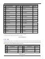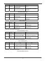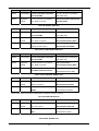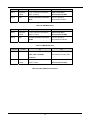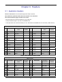
1
To our customers,
Old Company Name in Catalogs and Other Documents
On April 1st, 2010, NEC Electronics Corporation merged with Renesas Technology
Corporation, and Renesas Electronics Corporation took over all the business of both
companies. Therefore, although the old company name remains in this document, it is a valid
Renesas Electronics document. We appreciate your understanding.
Renesas Electronics website: http://www.renesas.com
April 1st, 2010
Renesas Electronics Corporation
Issued by: Renesas Electronics Corporation (http://www.renesas.com)
Send any inquiries to http://www.renesas.com/inquiry.
Notice
1.
2.
3.
4.
5.
6.
7.
All information included in this document is current as of the date this document is issued. Such information, however, is
subject to change without any prior notice. Before purchasing or using any Renesas Electronics products listed herein, please
confirm the latest product information with a Renesas Electronics sales office. Also, please pay regular and careful attention to
additional and different information to be disclosed by Renesas Electronics such as that disclosed through our website.
Renesas Electronics does not assume any liability for infringement of patents, copyrights, or other intellectual property rights
of third parties by or arising from the use of Renesas Electronics products or technical information described in this document.
No license, express, implied or otherwise, is granted hereby under any patents, copyrights or other intellectual property rights
of Renesas Electronics or others.
You should not alter, modify, copy, or otherwise misappropriate any Renesas Electronics product, whether in whole or in part.
Descriptions of circuits, software and other related information in this document are provided only to illustrate the operation of
semiconductor products and application examples. You are fully responsible for the incorporation of these circuits, software,
and information in the design of your equipment. Renesas Electronics assumes no responsibility for any losses incurred by
you or third parties arising from the use of these circuits, software, or information.
When exporting the products or technology described in this document, you should comply with the applicable export control
laws and regulations and follow the procedures required by such laws and regulations. You should not use Renesas
Electronics products or the technology described in this document for any purpose relating to military applications or use by
the military, including but not limited to the development of weapons of mass destruction. Renesas Electronics products and
technology may not be used for or incorporated into any products or systems whose manufacture, use, or sale is prohibited
under any applicable domestic or foreign laws or regulations.
Renesas Electronics has used reasonable care in preparing the information included in this document, but Renesas Electronics
does not warrant that such information is error free. Renesas Electronics assumes no liability whatsoever for any damages
incurred by you resulting from errors in or omissions from the information included herein.
Renesas Electronics products are classified according to the following three quality grades: “Standard”, “High Quality”, and
“Specific”. The recommended applications for each Renesas Electronics product depends on the product’s quality grade, as
indicated below. You must check the quality grade of each Renesas Electronics product before using it in a particular
application. You may not use any Renesas Electronics product for any application categorized as “Specific” without the prior
written consent of Renesas Electronics. Further, you may not use any Renesas Electronics product for any application for
which it is not intended without the prior written consent of Renesas Electronics. Renesas Electronics shall not be in any way
liable for any damages or losses incurred by you or third parties arising from the use of any Renesas Electronics product for an
application categorized as “Specific” or for which the product is not intended where you have failed to obtain the prior written
consent of Renesas Electronics. The quality grade of each Renesas Electronics product is “Standard” unless otherwise
expressly specified in a Renesas Electronics data sheets or data books, etc.
“Standard”:
8.
9.
10.
11.
12.
Computers; office equipment; communications equipment; test and measurement equipment; audio and visual
equipment; home electronic appliances; machine tools; personal electronic equipment; and industrial robots.
“High Quality”: Transportation equipment (automobiles, trains, ships, etc.); traffic control systems; anti-disaster systems; anticrime systems; safety equipment; and medical equipment not specifically designed for life support.
“Specific”:
Aircraft; aerospace equipment; submersible repeaters; nuclear reactor control systems; medical equipment or
systems for life support (e.g. artificial life support devices or systems), surgical implantations, or healthcare
intervention (e.g. excision, etc.), and any other applications or purposes that pose a direct threat to human life.
You should use the Renesas Electronics products described in this document within the range specified by Renesas Electronics,
especially with respect to the maximum rating, operating supply voltage range, movement power voltage range, heat radiation
characteristics, installation and other product characteristics. Renesas Electronics shall have no liability for malfunctions or
damages arising out of the use of Renesas Electronics products beyond such specified ranges.
Although Renesas Electronics endeavors to improve the quality and reliability of its products, semiconductor products have
specific characteristics such as the occurrence of failure at a certain rate and malfunctions under certain use conditions. Further,
Renesas Electronics products are not subject to radiation resistance design. Please be sure to implement safety measures to
guard them against the possibility of physical injury, and injury or damage caused by fire in the event of the failure of a
Renesas Electronics product, such as safety design for hardware and software including but not limited to redundancy, fire
control and malfunction prevention, appropriate treatment for aging degradation or any other appropriate measures. Because
the evaluation of microcomputer software alone is very difficult, please evaluate the safety of the final products or system
manufactured by you.
Please contact a Renesas Electronics sales office for details as to environmental matters such as the environmental
compatibility of each Renesas Electronics product. Please use Renesas Electronics products in compliance with all applicable
laws and regulations that regulate the inclusion or use of controlled substances, including without limitation, the EU RoHS
Directive. Renesas Electronics assumes no liability for damages or losses occurring as a result of your noncompliance with
applicable laws and regulations.
This document may not be reproduced or duplicated, in any form, in whole or in part, without prior written consent of Renesas
Electronics.
Please contact a Renesas Electronics sales office if you have any questions regarding the information contained in this
document or Renesas Electronics products, or if you have any other inquiries.
(Note 1) “Renesas Electronics” as used in this document means Renesas Electronics Corporation and also includes its majorityowned subsidiaries.
(Note 2) “Renesas Electronics product(s)” means any product developed or manufactured by or for Renesas Electronics.
User’s Manual
Renesas Starter Kit+ for SH7203
User’s Manual
RENESAS SINGLE-CHIP MICROCOMPUTER
SuperH™RISC engine
Rev.2.00 2008.01
Table of Contents
Chapter 1. Preface ..................................................................................................................................................1
Chapter 2. Purpose .................................................................................................................................................2
Chapter 3. Power Supply ........................................................................................................................................3
3.1. Requirements ...............................................................................................................................................3
3.2. Power – Up Behaviour .................................................................................................................................3
Chapter 4. Board Layout .........................................................................................................................................4
4.1. Component Layout .......................................................................................................................................4
4.2. Board Dimensions ........................................................................................................................................5
Chapter 5. Block Diagram .......................................................................................................................................6
Chapter 6. User Circuitry.........................................................................................................................................7
6.1. Switches .......................................................................................................................................................7
6.2. LEDs.............................................................................................................................................................7
6.3. Potentiometer ...............................................................................................................................................7
6.4. Serial port .....................................................................................................................................................8
6.5. Debug LCD Module ......................................................................................................................................8
6.6. RCAN ...........................................................................................................................................................8
6.7. USB ..............................................................................................................................................................9
6.8. ETHERNET ..................................................................................................................................................9
6.9. LCD Interface ...............................................................................................................................................9
6.10. SSI ............................................................................................................................................................ 11
6.11. Option Links..............................................................................................................................................12
6.12. DIP Switch Settings ..................................................................................................................................12
6.13. Oscillator Sources ....................................................................................................................................17
6.14. Reset Circuit .............................................................................................................................................17
Chapter 7. Modes..................................................................................................................................................18
Chapter 8. Programming Methods........................................................................................................................19
8.1. H-UDI Header for E10A..............................................................................................................................19
8.2. AUD Header for E10A ................................................................................................................................19
Chapter 9. Headers...............................................................................................................................................20
9.1. Application Headers ...................................................................................................................................20
Chapter 10. Code Development ...........................................................................................................................23
10.1. Overview...................................................................................................................................................23
10.2. Compiler Restrictions ...............................................................................................................................23
10.3. Breakpoint Support...................................................................................................................................23
10.4. Memory Map.............................................................................................................................................24
Chapter 11. Component Placement ......................................................................................................................25
Chapter 12. Additional Information........................................................................................................................27
ii
Chapter 1. Preface
Cautions
This document may be, wholly or partially, subject to change without notice.
All rights reserved. No one is permitted to reproduce or duplicate, in any form, a part or this entire document without the written
permission of Renesas Technology Europe Limited.
Trademarks
All brand or product names used in this manual are trademarks or registered trademarks of their respective companies or
organisations.
Copyright
© Renesas Technology Europe Ltd. 2008. All rights reserved.
© Renesas Technology Corporation. 2008. All rights reserved.
© Renesas Solutions Corporation. 2008. All rights reserved.
Website:
http://www.renesas.com/
Glossary
RSK
Renesas Starter Kit
RSK+
Renesas Starter Kit plus
LCD
Liquid Crystal Display
ADC
Analog to Digital Converter
CPU
Central Processing Unit
LED
Light Emitting Diode
E10A
‘E10A for Starter Kits’ Debugger
AUD
Advanced User Debugger
H-UDI
Hitachi - User Debug Interface
USB
Universal Serial Bus
SSI
Serial sound Interface
RCAN
Renesas Controller Area Network
DIP
Dual-In-Line package
1
Chapter 2. Purpose
This RSK+ is an evaluation tool for Renesas microcontrollers.
Features include:
•
Renesas Microcontroller Programming.
•
User Code Debugging.
•
User Circuitry such as switches, LEDs and potentiometer(s).
•
Sample Application.
•
Sample peripheral device initialisation code.
The CPU board contains all the circuitry required for microcontroller operation.
This manual describes the technical details of the RSK+SH7203 hardware. The Quick Start Guide and Tutorial Manual provide details of
the software installation and debugging environment.
2
Chapter 3. Power Supply
3.1. Requirements
This CPU board can operate from either a 5V power supply or an 8V to 15V supply.
Please refer to the following table while selecting the power supply voltage range -
Power Supply
Jumpers SEL_5VA and
Jumpers SEL_5VA and
SEL_5VB Fitted
SEL_5VB Removed
5V only
8V to 15V (Default setting)*
* - 12V power supply is included with the RSK+ board.
Table 3-1 Power Supply Options
Warning - Care must be taken to ensure that an appropriate supply is used. Failing to do this may cause permanent damage to
the board.
A diode provides reverse polarity protection only if a current limiting power supply is used.
All CPU boards have a centre positive supply connector using a 2.0mm barrel power jack.
Warning - The CPU board is not over voltage protected. Use a centre positive supply for this board.
3.2. Power – Up Behaviour
When the RSK+ is purchased the CPU board has the ‘Release’ or stand alone code from the example tutorial code pre-programmed into
the Renesas microcontroller. On powering up the board the user LEDs will start to flash. Pressing any switch will cause the LEDs to flash
at a rate controlled by the potentiometer.
3
Chapter 4. Board Layout
4.1. Component Layout
The following diagram shows top layer component layout of the board.
Figure 4-1: Board Layout
4
4.2. Board Dimensions
The following diagram gives the board dimensions and connector positions. All through hole connectors are on a common 0.1” grid for easy
5
143.50mm
135.00mm
65.00mm
47.00mm
LCD
Figure 4-2 : Board Dimensions
150.00mm
JA5A
JA1A
JA2A
JA6A
6.50mm
interfacing.
Chapter 5. Block Diagram
Figure 5-1 shows the CPU board components and their connectivity.
Power Jack Option
LCD Panel Connectors
External Flash ROM
(4MB)
RCAN Connectors
External SDRAM
(16MB)
100 Mbps Ethernet Connector
Microcontroller
USB Host & Function Connectors
RESET pin
Serial Sound Interface Connector
RESET IC
IRQ pin
IRQ pin
IRQ pin
Application Headers
Debug Headers Option
RESn
ADC Input
Serial Connector Option
SW3
DIP Switches
SW2
SW1
RES
Potentiometer
SWITCHES
LEDs
User: 4 LEDS
1Green, 1Orange, 2Red
Figure 5-1: Block Diagram
Figure 5-2 shows the connections to the RSK+ board.
Figure 5-2 : RSK+ Connections
6
Power: Green
Chapter 6. User Circuitry
6.1. Switches
There are four switches located on the CPU board. The function of each switch and its connection are shown in Table 6-1.
Switch
Function
Microcontroller
RES
When pressed; the CPU board microcontroller is reset.
RESn, Pin 59
SW1*
Connects to an IRQ input for user controls. SW6-8 needs to be ON.
IRQ0, Pin 179
(Port B, bit 0)
SW2*
Connects to an IRQ line for user controls. SW6-5 needs to be ON.
IRQ1, Pin 180
(Port B, bit 1)
SW3*
Connects to an IRQ line for user controls. SW6-3 needs to be ON.
IRQ2, Pin 181
(Port B, bit 2)
* - Please refer to Table 6-25 to Table 6-27 for details on DIP switch settings.
Table 6-1 Switch Functions
6.2. LEDs
There are 6 LEDs on the CPU board. The green ‘POWER’ LED lights when the board is powered. The four user LEDs are connected to an
IO port and will light when their corresponding port pin is set low. An Orange LED “LED4” will lit when the Ethernet link operates in Full
Duplex mode.
Table 6-2 below, shows the LED pin references and their corresponding microcontroller port pin connections.
LED Reference (As shown
Microcontroller Port Pin function
Microcontroller Pin Number
Polarity
LED0
Port E bit 10
71
Active Low
LED1*
Port E bit 12
73
Active Low
LED2*
Port C bit 14
75
Active Low
LED3*
Port E bit 11
72
Active Low
on silkscreen)
* - Please refer to Table 6-13, Table 6-20 and Table 6-21 for details on DIP switch settings.
Table 6-2 LED Ports
6.3. Potentiometer
A single turn potentiometer is connected to AN0 of the microcontroller via an option resistor ‘R67’ (which is fitted by default). This may be
used to vary the input analog voltage value to this pin between AVCC and Ground.
7
6.4. Serial port
The microcontroller serial port SCIF0 can be used for RS232 communication. Please refer to Table 6-3 for the option links related with the
serial portsDescription
Function
Fit for RS232
Remove to use
alternate function
TxD0
Serial Port Tx Pin
R103
R103
RxD0
Serial Port Rx Pin
R98
R98
Table 6-3 Serial Option Links
The board is designed to accept a straight through RS232 cable.
6.5. Debug LCD Module
The LCD module supplied with the RSK can be connected to the connector ‘LCD’ for use with the tutorial code. Any module that conforms
to the pin connections and has a KS0066u compatible controller can be used. The LCD module uses a 4bit interface to reduce the pin
allocation. No contrast control is provided; this must be set on the display module.
The module supplied with the CPU board only supports 5V operation.
Table 6-4 shows the pin allocation and signal names used on this connector.
LCD
Pin
Circuit Net Name
Device
Pin
Circuit Net Name
Pin
Device
Pin
1
Ground
-
2
5V Only
-
3
No Connection
-
4
DLCDRS
138
5
R/W (Wired to Write only)
-
6
DLCDE
148
7
No Connection
-
8
No connection
-
9
No Connection
-
10
No connection
-
11
DLCD4
140
12
DLCD5
136
13
DLCD6
135
14
DLCD7
134
Table 6-4 Debug LCD Module Connections
6.6. RCAN
Two RCAN ports are available on this board. The SH7203 on-chip RCAN module offers a flexible and sophisticated way to organise and
control CAN frames, providing the compliance to CAN2.0B Active and ISO-11898-1. Table 6-5 details the CAN connectors available on
this RSK+ board -
8
CAN0
Pin
Circuit Net Name
CAN1
Device Pin
Pin
Circuit Net Name
Device Pin
1
CTx0
86*
1
CTx1
88*
2
GROUND
-
2
GROUND
-
3
CRx0
85*
3
CRx1
87*
* - The RCAN transceivers translate the voltage levels on CPU pin to meet RCAN voltage level standards.
Table 6-5 RCAN Connectors
For more details on SH7203 on-chip RCAN module, please refer to SH7203 Group Hardware Manual.
6.7. USB
The USB 2.0 host/function module (USB) provides capabilities as a USB host and USB function. It supports high-speed and full-speed
transfers defined by USB specification 2.0. The Low speed mode is not supported. This module has a USB transceiver and supports all of
the transfer types defined by the USB specification. The module has an 8-kbyte on-chip buffer memory for data transfer, providing a
maximum of eight pipes. Any endpoint numbers can be assigned to PIPE1 to PIPE7, based on the peripheral devices or user system for
communication. Please note that, a 5V power supply needs to be used while connecting a USB powered device (to the USB Host
connector of the RSK+SH7203) if more than 25mA current is required to be sourced. See 3.1.
Table 6-6 below details the USB connectors available on this RSK+ board.
USB_H (USB Host)
Pin
1
Circuit Net Name
HOST_VBUS
USB_D (USB Device / Function)
Device Pin
Pin
See SW4-2
1
Circuit Net Name
DEVICE_VBUS*
to SW4-5
Device Pin
See SW4-2
to SW4-5
2
USD -
100
2
USD -
100
3
USD +
101
3
USD +
101
4
GROUND
-
4
NC
-
5
GROUND
-
* - The connection is via SW4-5.
Table 6-6 USB Connectors
For more details on SH7203 on-chip USB module, please refer to SH7203 Group Hardware Manual.
6.8. ETHERNET
The network functionality is provided by the SMCS LAN9118-MT non-PCI Ethernet controller. The Ethernet controller is configured to
use a 16 bit data bus. It uses single 16 bit read and write strobes. Byte or long word accesses are not available for this device. The chip
select used for the network controller is CS1n.
Refer to the SMCS LAN9118-MT datasheet for more information on this peripheral.
6.9. LCD Interface
Unified memory architecture is adopted for the LCD controller (LCDC) so that the image data for display is stored in system memory. The
LCDC module reads data from system memory, uses the palette memory to determine the colours, and then puts the display on the LCD
9
panel. It is possible to connect the LCDC to the LCD module other than microcomputer bus interface types and NTSC/PAL types and those
that apply the LVDS interface.
Two separate headers are provided on the RSK+ boards to support two types of LCDs 1.
Hitachi LCD (J4)
2. Generic LCD (J14)
Table 6-7 and Table 6-8 below details the LCD headers available on this RSK+ board.
J4 (For Hitachi LCD)
Pin
CPU board Signal Name
Device Pin
Pin
CPU board Signal Name
Device Pin
1
GROUND
---
2
GROUND
---
3
GROUND
---
4
LCD_VCC
---
5
LCD_VCC
---
6
LCD_VCC
---
7
GROUND
---
8
BLCD_DATA0
169*
9
BLCD_DATA1
167*
10
BLCD_DATA2
166*
11
BLCD_DATA3
165*
12
BLCD_DATA4
164*
13
BLCD_DATA5
163*
14
BLCD_DATA6
162*
15
BLCD_DATA7
161*
16
BLCD_DATA8
160*
17
BLCD_DATA9
158*
18
BLCD_DATA10
155*
19
GROUND
---
20
BLCD_DATA11
153*
21
BLCD_DATA12
152*
22
BLCD_DATA13
151*
23
BLCD_DATA14
150*
24
BLCD_DATA15
149*
25
BLCD_DOTCLK
137*
26
BLCD_HSYNC
147*
27
BLCD_VSYNC
139*
28
BSSCS0
210**
29
BSSCK0
213**
30
BSSO0
211**
31
SSI0
212***
32
BLCD_RESn
59*
33
GROUND
---
34
VLED +
---
35
VLED +
---
36
VLED -
---
37
VLED -
---
38
GROUND
---
39
GROUND
--Table 6-7 LCD Header J4
10
J14 (For Generic LCD)
Pin
CPU board Signal Name
Device Pin
Pin
CPU board Signal Name
Device Pin
1
BOARD_5V
---
2
BOARD_5V
---
3
LCD_VCC
---
4
LCD_VCC
---
5
Unregulated_VCC
---
6
Unregulated_VCC
---
7
BLCD_DATA0
169*
8
BLCD_DATA1
167*
9
BLCD_DATA2
166*
10
BLCD_DATA3
165*
11
BLCD_DATA4
164*
12
BLCD_DATA5
163*
13
BLCD_DATA6
162*
14
BLCD_DATA7
161*
15
BLCD_DATA8
160*
16
BLCD_DATA9
158*
17
BLCD_DATA10
155*
18
BLCD_DATA11
153*
19
BLCD_DATA12
152*
20
BLCD_DATA13
151*
21
BLCD_DATA14
150*
22
BLCD_DATA15
149*
23
BLCD_DON
148*
24
BLCD_HSYNC
147*
25
BLCD_DOTCLK
137*
26
BLCD_MDISP
138*
27
BLCD_VSYNC
139*
28
DLCDD4 (LCD CLK)
140
29
BSSCK0
213**
30
SSI0
212***
31
BSSO0
211**
32
BSSCS0
210**
33
BLCD_RESn
59*
34
GROUND
---
35
BLCD_VCPWC
142*
36
BLCD_VEPWC
145*
37
GROUND
---
38
GROUND
---
39
GROUND
---
40
GROUND
---
* - These CPU pins are externally buffered (U15 and U16).
** - TheseCPU pins are externally buffered and multiplexed (Please refer to Table 6-10 for more details).
*** - These pins are externally multiplexed (Please refer to Table 6-10 for more details).
Table 6-8 LCD Header J14
6.10. SSI
The serial sound interface (SSI) is a module designed to send or receive audio data interface with various devices offering Philips format
compatibility. It also provides additional modes for other common formats, as well as support for multi-channel mode. Both transmitter and
receiver modules are embedded. Table 6-9 below details the SSI header.
J2
Pin
Circuit Net Name
Device Pin
Pin
Circuit Net Name
Device Pin
1
Unregulated_VCC
-
2
Board_VCC
-
3
SSISCK3
126
4
SSIWS3
125
5
SSIDATA3
124
6
AUDIOCLK*
128
7
GROUND
-
* - Please refer to Table 6-15 for more details.
Table 6-9 SSI Header
11
For more details on SH7203 on-chip Serial Sound Interface module, please refer to SH7203 Group Hardware Manual.
6.11. Option Links
Table 6-10 to Table 6-12 below describes the function of the option links contained on this CPU board. The default configuration is
indicated by BOLD text.
Reference
CPU Pin
Fitted
Alternative ( Removed )
Related To
R55
PA7, Pin 119
Connects PIN 119 of the CPU to
Disconnects PIN 119 of the CPU
R56
DA1 on JA5A and JA5B.
from DA1.
Connects PIN 119 of the CPU to AN7
Disconnects PIN 119 of the CPU
on JA5A and JA5B.
from AN7.
R56
PA7, Pin 119
R55
Table 6-10 Option Link for ADPOT_AN0
Reference
CPU Pin
Fitted
Alternative ( Removed )
Related To
R57
PA6, Pin 118
Connects PIN 118 of the CPU to
Disconnects PIN 118 of the CPU
R61
DA0 on JA1A and JA1B.
from DA0.
Connects PIN 118 of the CPU to AN6
Disconnects PIN 118 of the CPU
on JA5A and JA5B.
from AN6.
R61
PA6, Pin 118
R57
Table 6-11 Option Link for AN6_DA0
Reference
CPU Pin
Fitted
Alternative ( Removed )
Related To
R67
PA0, Pin 110
Connects PIN 110 of the CPU to
Disconnects PIN 110 of the CPU
R72
AD_POT.
from AD_POT.
Connects PIN 110 of the CPU to AN0
Disconnects PIN 110 of the CPU
on JA1A and JA1B.
from AN0.
R72
PA0, Pin 110
Table 6-12 Option Link for AN7_DA1
6.12. DIP Switch Settings
The default configuration is indicated by BOLD text.
Reference
SW4-1
Function
User LEDs
ON
OFF
Port pin PE12 (CPU PIN 73) drives
LED1 off
LED1
SW4-2
USB
Port Pin PE12 of the CPU controls 5V
5V supply to the USB connector is
supply to the USB HOST connector.
on if by SW4-3 is on, otherwise it is
off.
SW4-3
USB
Host_VBUS is 5V.
5V supply to the USB connector is
controlled by Port pin PE12 if SW4-2 is
on, otherwise it is off
Note: Do not set SW4-2 and SW4-3.
Table 6-13 LED1 and USB power control.
12
R67
Reference
SW4-4
SW4-5
Function
USB
USB
ON
OFF
VBUS (pin 102) of the CPU monitors
HOST_VBUS_FLAG is disconnected
Host VBUS.
from VBUS (pin 102) of the CPU.
VBUS (pin 102) of the CPU monitors
DEVICE_VBUS is disconnected from
Device VBUS.
VBUS (Pin 102) of the CPU.
Please note that only one switch can be set to ON.
Table 6-14 VBUS connection
Reference
SW4-6
SW4-7
Function
SSI
RCAN
ON
OFF
PF30 (Pin 128) of the CPU can be
AUDIOCLK signal on J2 is
used as AUDIOCLK signal on J2.
disconnected from Pin 128 of the CPU.
PF30 (Pin 128) of the CPU can be
Pin 128 of the CPU can not be used as
used as CAN1_EN.
CAN1_EN signal.
Please note that only one switch can be set to ON.
Table 6-15 PF30 function select
Reference
SW4-8
SW4-9
Function
ON
OFF
CLOCK
The MD_CLK0 (Pin 97) of the CPU
The MD_CLK0 (Pin 97) of the CPU
Mode
logic 0
logic 1
CLOCK
The MD_CLK1 (Pin 96) of the CPU
The MD_CLK1 (Pin 96) of the CPU
Mode
logic 0
logic 1
Table 6-16 Clock mode settings
Reference
SW4-10
Function
BUS Interface
ON
OFF
16 bit bus interface is selected for
32 bit bus interface is selected
SDRAM access. Port functions on
for SDRAM access.
upper 16 bits.
Table 6-17 32 bit/16 bit select
Reference
Function
ON
OFF
SW5-1
LCD / NAND
Pin 147 of the CPU is connected to
NAND flash disabled
FLASH
NAND_CSn pin of NAND Flash.
Table 6-18 NAND Flash enable
Reference
Function
ON
OFF
SW5-2
External ROM
Disables writing to the External Flash
Enables writing to the External Flash
memory.
memory.
Table 6-19 Flash protection
13
Reference
Function
ON
OFF
SW5-3
User LEDs
Port pin PC14 (CPU PIN 75) can be
LED 2 off
used to drive LED2.
SW5-4
Bus Interface
Pin 75 of the CPU can be used as
Pin 75 of the CPU can not be used as
WAITn input available on JA3A-49.
WAITn input.
Table 6-20 LED2 / WAITn control
Reference
Function
ON
OFF
SW5-5
User LEDs
Port pin PE11 (CPU PIN 72) can be
LED3 off.
used to drive LED3.
SW5-6
Bus Interface
Pin 72 of the CPU can be used as
Pin 72 of the CPU can not be used as
CS6n output.
CS6n output.
Table 6-21 LED3 / CS6n
Reference
Function
ON
OFF
SW5-7
Bus interface
Pin 17 of the CPU can be used as A0
Pin 17 of the CPU can not be used as
address output.
A0 address output.
Pin 17 of the CPU can be used as
Pin 17 of the CPU can not be used as
AUDSYNCn output.
AUDSYNCn output.
SW5-8
AUD interface
Please note that only one switch can be set to ON.
Table 6-22 A0/AUDSYNCn selection
Reference
Function
ON
OFF
SW5-9
Application
Pin 192 of the CPU (ADTRGn) is
Pin 192 of the CPU (ADTRGn) is
Headers
connected to user switch SW3.
disconnected from user switch SW3.
Application
Pin 192 of the CPU is connected to
Pin 192 of the CPU is disconnected
Headers
EXT_ADTRG available on JA1A-8.
from EXT_ADTRG.
SW5-10
Please note that SW4-10 must be off (16 Bit mode) to enable ADTRGn
Table 6-23 ADTRGn selection
Reference
SW6-1
SW6-2
Function
ON
OFF
Pin 182 of the CPU is connected to
Pin 182 of the CPU is disconnected
ETH_PME pin of Ethernet controller.
from ETH_PME.
Application
Pin 182 of the CPU is connected to
Pin 182 of the CPU is disconnected
Header
EXT_IRQ3n on JA1A-23.
from EXT_IRQ3n.
Ethernet
Please note that only one switch can be set to ON.
Table 6-24 ETH_PME /EXT_IRQ3 select
14
Reference
SW6-3
SW6-4
Function
ON
OFF
Pin 181 of the CPU is connected to
Pin 181 of the CPU is connected to
User switch SW3.
User switch SW3.
Application
Pin 181 of the CPU is connected to
Pin 181 of the CPU is disconnected
Header
EXT_IRQ2n on JA2A-23.
from EXT_IRQ2n.
User Switches
Table 6-25 SW3/EXT_IRQ2 select
Reference
SW6-5
SW6-6
SW6-7
Function
ON
OFF
Pin 180 of the CPU is connected to
Pin 180 of the CPU is connected to
User switch SW2.
User switch SW2.
Application
Pin 180 of the CPU is connected to
Pin 180 of the CPU is
Header
EXT_IRQ1n on JA2A-23.
disconnected from EXT_IRQ1n.
Bus interface
Pin 180 of the CPU is connected to
Pin 180 of the CPU is
RDYBYn of Flash memory.
disconnected from RDYBYn.
User Switches
Table 6-26 EXT_IRQ1n/RDYBYn/SW2 select
Reference
SW6-8
SW6-9
SW6-10
Function
ON
OFF
Pin 179 of the CPU is connected to
Pin 179 of the CPU is connected to
User switch SW1.
User switch SW1.
Application
Pin 179 of the CPU is connected to
Pin 179 of the CPU is
Header
EXT_IRQ0n on JA2A-23.
disconnected from EXT_IRQ0n.
Bus interface
Pin 179 of the CPU is connected to
Pin 179 of the CPU is
ETH_IRQn of Ethernet controller.
disconnected from ETH_IRQn.
User Switches
Table 6-27 EXT_IRQ0n/ETH_IRQ/SW1 select
Reference
SW7-1
SW7-2
Function
ON
OFF
Application
Pin 213 of the CPU is connected to
Pin 213 of the CPU is
Header
TRISTn on JA2A-24.
disconnected from TRISTn.
SSU
Pin 213 of the CPU is connected to
Pin 213 of the CPU is
SSCK0.
disconnected from SSCK0.
Please note that SW4-10 must be off (16 Bit mode) to enable Port functions on this pin
Table 6-28 TRISTn/SSCK0 select
Reference
SW7-3
SW7-4
Function
ON
OFF
Application
Pin 212 of the CPU is connected to
Pin 212 of the CPU is
Header
MO_UD on JA2A-11.
disconnected from MO_UD.
SSU
Pin 212 of the CPU is connected to
Pin 212 of the CPU is
SSI0.
disconnected from SSI0.
Please note that SW4-10 must be off (16 Bit mode) to enable Port functions on this pin
Table 6-29 MO_UD/SSIO select
15
Reference
SW7-5
SW7-6
Function
ON
OFF
Application
Pin 211 of the CPU is connected to
Pin 211 of the CPU is
Header
TMR1 on JA2A-20.
disconnected from TMR1.
SSU
Pin 211 of the CPU is connected to
Pin 211 of the CPU is
SSO0.
disconnected from SSO0.
Please note that SW4-10 must be off (16 Bit mode) to enable Port functions on this pin
Table 6-30 TMR1/SSO0 select
Reference
SW7-7
SW7-8
Function
ON
OFF
Application
Pin 210 of the CPU is connected to
Pin 210 of the CPU is
Header
TMR0 on JA2A-19.
disconnected from TMR0.
SSU
Pin 210 of the CPU is connected to
Pin 210 of the CPU is
SSCS0.
disconnected from SSCS0.
Please note that SW4-10 must be off (16 Bit mode) to enable Port functions on this pin
Table 6-31 TMR1/SSCS0 select
Reference
SW7-9
Function
RCAN
ON
OFF
Pin 209 of the CPU is connected to
Pin 209 of the CPU is
CAN1_STBn of the RCAN
disconnected from CAN1_STBn.
transceiver.
SW7-10
Application
Pin 209 of the CPU is connected to
Pin 209 of the CPU is
Header
SCK2 on JA6A-11.
disconnected from SCK2.
Please note that SW4-10 must be off (16 Bit mode) to enable ADTRGn
Table 6-32 CAN1_STBn/Serial clock2 select
16
6.13.Oscillator Sources
A crystal oscillator is fitted on the CPU board and used to supply various clock inputs to the Renesas microcontroller. Table 6-33 details
the oscillators that are fitted and alternative footprints provided on this CPU board:
Reference
Component
Crystal (X1)
Fitted
16.6675 MHz (HC49/4H package)
Crystal (X2)
Fitted
32.768 kHz (90SMX package)
Crystal (X3)
Fitted
24.576 MHz (HC49/4H)
Crystal (X4)
Fitted
48 MHz (HC49/4H package)
Table 6-33 Crystal Oscillators
6.14. Reset Circuit
The CPU Board includes a Reset IC MAX6863 (U3) to meet the minimum reset period of 10ms. Please refer to the hardware manual for
more information on the requirements of the reset circuit. Please check the reset requirements carefully to ensure the reset circuit on the
user’s board meets all the reset timing requirements.
17
Chapter 7. Modes
This CPU board supports four clock modes. Please refer to Table 7-1 for clock mode selection.
SW4-9 (CPU Pin 96, MD_CLK1)
SW4-8 (CPU Pin 97, MD_CLK0)
Clock Mode
ON
ON
0
ON
OFF
1
OFF
ON
2
OFF
OFF
3
Table 7-1 Clock Mode Selection
a.
Clock Mode 0 – This is the default mode on RSK+SH7203. In mode 0, clock is input from the EXTAL pin or the crystal
oscillator. The PLL circuit shapes waveforms and the frequency is multiplied according to the frequency control register setting
before the clock is supplied to the LSI. The oscillating frequency for the crystal resonator and EXTAL pin input clock ranges
from 10 to 16.67 MHz. The frequency range of CKIO is from 40 to 66.67 MHz.
b.
Clock Mode 1 - In mode 1, clock is input from the EXTAL pin or the crystal oscillator. The PLL circuit shapes waveform and
the frequency is multiplied according to the frequency control register setting before the clock is supplied to the LSI. The
oscillating frequency for the crystal resonator and EXTAL pin input clock ranges from 20 to 33.33 MHz. The frequency range of
CKIO is from 40 to 66.67 MHz.
c.
Clock Mode 2 - In mode 2, the CKIO pin functions as an input pin and draws an external clock signal. The PLL circuit shapes
waveform and the frequency is multiplied according to the frequency control register setting before the clock is supplied to the
LSI. The frequency range of CKIO is from 40 to 66.67 MHz.
d.
Clock Mode 3 - In mode 3, clock is input from the USB_X1 pin or the crystal oscillator. The external clock is input through this
pin and waveform is shaped in the PLL circuit. Then the frequency is multiplied according to the frequency control register
setting before the clock is supplied to the LSI. The frequency of CKIO is the same as that of the input clock (USB_X1/crystal
resonator) (48 MHz).
Warning - While changing the clock mode please ensure that correct Frequency Multiplication/division Ratios are set in the FRQCR
register. Permanent damage may occur to the CPU due to overheat if incorrect clock is selected.
18
Chapter 8. Programming Methods
The RSK+SH7203 board can be programmed using E10A-lite supplied with the kit. Following headers are provided to download and
debug the user code – H-UDI and AUD.
8.1. H-UDI Header for E10A
This is a 14 pin header used to download and debug the user program. This header provides H-UDI interface for user debugging. Limited
Event conditions in ROM and unlimited Breakpoints in RAM are supported. The AUD trace function is not supported. Since the 14-pin type
connector is smaller than the 36-pin type (1/2.5), the area where the connector is installed on the user system can be reduced.
8.2. AUD Header for E10A
This is a 36 pin header used to download and debug the user program. This header provides additional AUD trace functions for user
debugging. A large amount of trace information can be acquired in realtime. The window trace function is also supported for acquiring
memory access in the specified range (memory access address or memory access data) by tracing. Limited Event conditions in ROM and
unlimited Breakpoints in RAM are supported.
User system interface cable for AUD header is not provided with this CPU board. This can be purchased at additional cost from the local
Renesas distributor. A list of worldwide Renesas distributors is available on the Renesas website - www.renesas.com
19
Chapter 9. Headers
9.1. Application Headers
Table 9-1 to Table 9-5 below show the standard application header connections.
Note: Switch ID is specified in brackets where the connection is via a DIP switch.
Note: Asterisk indications apply to all tables in this section
* marks pins where a link to the microcontroller pin is via an option link
** marks pins where the signal is only valid in 16 bit SDRAM mode
*** marks pins where a link to the microcontroller pin is via a 100R resistor and to BOARD VCC via a 4k7 resistor (100R ID & 4k7 ID)
JA1A and JA1B
Pin
Header Name
CPU board Signal
Device Pin /
Name
DIP S/W
Pin
Header Name
CPU board Signal
Device Pin /
Name
DIP S/W
1
5V
CON_5V
---
2
0V (5V)
GROUND
---
3
3V3
CON_3V3
---
4
0V (3V3)
GROUND
---
5
AVcc
AVCC
114
6
AVss
AVSS
120
7
AVref
AVREF
116
8
ADTRG
EXT_ADTRG
192 (SW5-10)
9
ADC0
AN0*
110
10
ADC1
AN1
111
11
ADC2
AN2
112
12
ADC3
AN3
113
13
DAC0
DA0*
118
14
DAC1
DA1*
119
15
IO Port0
LCD_DATA0_IO0
169
16
IO Port1
LCD_DATA1_IO1
167
17
IO Port2
LCD_DATA2_IO2
166
18
IO Port3
LCD_DATA3_IO3
165
19
IO Port4
LCD_DATA4_IO4
164
20
IO Port5
LCD_DATA5_IO5
163
21
IO Port8
LCD_DATA6_IO6
162
22
IO Port7
LCD_DATA7_IO7
161
23
IRQ3
EXT_IRQ3n
182 (SW6-2)
24
I2C Bus (3rd pin)
JA1_PIN24
---
25
IIC_SDA
SDA2***
186
26
IIC_SCL
SCL2***
185
Table 9-1: JA1A / JA1B Standard Generic Header
JA2A and JA2B
Pin
Header Name
CPU board Signal
Device Pin /
Name
DIP S/W
Pin
Header Name
CPU board
Device Pin /
Signal Name
DIP S/W
1
RESn
RESn
59
2
EXTAL
CON_EXTAL
3
NMI
NMIn
57
4
VSS1
VSS1 (GND)
---
5
WDT Overflow
---
---
6
SCIaTX
TxD0
63
7
IRQ0
EXT_IRQ0
179 (SW6-9)
8
SCIaRx
RxD0
49
9
IRQ1
EXT_IRQ1
180 (SW6-6)
10
SCIaCK
JA2_PIN10
---
11
UD
MO_UD**
212 (SW7-3)
12
CTSRTS
JA2_PIN12
---
13
Up
MO_Up**
193
14
Un
MO_Un**
194
20
15
Vp
MO_Vp**
195
16
Vn
MO_Vn**
197
17
Wp
MO_Wp**
202
18
Wn
MO_Wn**
203
19
TMR0
TMR0**
51 (SW7-7)
20
TMR1
TMR1**
211 (SW7-5)
21
TRIGa
TRIGa**
31
22
TRIGb
TRIGb**
208
23
IRQ2
EXT_IRQ2n
181 (SW6-4)
24
TRISTn
TRISTn**
213 (SW7-1)
25
SPARE PIN
---
---
26
SPARE PIN
---
---
CPU board
Device Pin
Table 9-2: JA2A / JA2B Standard Generic Header
JA3A and JA3B
Pin
Header Name
CPU board
Device Pin
Pin
Header Name
Signal Name
Signal Name
1
A0
BA(0)
-
2
A1
BA(1)
-
3
A2
BA(2)
-
4
A3
BA(3)
-
5
A4
BA(4)
-
6
A5
BA(5)
-
7
A6
BA(6)
-
8
A7
BA(7)
-
9
A8
BA(8)
-
10
A9
BA(9)
-
11
A10
BA(10)
-
12
A11
BA(11)
-
13
A12
BA(12)
-
14
A13
BA(13)
-
15
A14
BA(14)
-
16
A15
BA(15)
-
17
D0
BD(0)
-
18
D1
BD(1)
-
19
D2
BD(2)
-
20
D3
BD(3)
-
21
D4
BD(4)
-
22
D5
BD(5)
-
23
D6
BD(6)
-
24
D7
BD(7)
-
25
RDn
BRDn
-
26
WRn
BWRn
-
27
CS1n
BCS2n
-
28
CS2n
BCS5n
-
29
D8
BD(8)
-
30
D9
BD(9)
-
31
D10
BD(10)
-
32
D11
BD(11)
-
33
D12
BD(12)
-
34
D13
BD(13)
-
35
D14
BD(14)
-
36
D15
BD(15)
-
37
D16
BD(16)
-
38
D17
BD(17)
-
39
D18
BD(18)
-
40
D19
BD(19)
-
41
D20
BD(20)
-
42
D21
BD(21)
-
43
D22
BD(22)
-
44
SDCLK
BCLKIO
-
45
CS2n
BCS6n
-
46
ALE
JA3_PIN46
-
47
WRHn
BWR1n
-
48
WRLn
BWR0n
-
49
WAITn
WAIT
-
50
Reserved
JA3_PIN50
---
Table 9-3: JA3A / JA3B Standard Generic Header
21
JA5A and JA5B
Pin
Header Name
CPU board
Device Pin
Pin
Header Name
Signal Name
CPU board
Device Pin
Signal Name
1
AD4
AN4
115
2
AD5
AN5
116
3
AD6
AN6*
118
4
AD7
AN7*
119
5
CAN1TX
CTx0
86
6
CAN1RX
CRx0
85
7
CAN2TX
CTx1
88
8
CAN2RX
CRx1
87
9
AD8
JA5_PIN9
---
10
AD9
JA5_PIN10
---
11
AD10
JA5_PIN11
---
12
AD11
JA5_PIN12
---
13
TIOC0A
JA5_PIN13
---
14
TIOC0B
JA5_PIN14
---
15
TIOC0C
JA5_PIN15
---
16
M2_TRISTn
JA5_PIN16
---
17
TCLKC
JA5_PIN17
---
18
TCLKD
JA5_PIN18
---
19
M2_Up
JA5_PIN19
---
20
M2_Un
JA5_PIN20
---
21
M2_Vp
JA5_PIN21
---
22
M2_Vn
JA5_PIN22
---
23
M2_Wp
JA5_PIN23
---
24
M2_Wn
JA5_PIN24
---
Table 9-4: JA5A / JA5B Standard Generic Header
JA6A and JA6B
Pin
Header Name
CPU board
Device Pin
Pin
Header Name
Signal Name
CPU board
Device Pin
Signal Name
1
DREQ
DREQ0
201
2
DACK
DACK0
200
3
TEND
TEND0
199
4
STBYn
JA6_PIN4
---
5
RS232TX
RS232TX
---
6
RS232RX
RS232RX
---
7
SCIbRx
RxD1
64
8
SCIbTX
TxD1
66
9
SCIcTx
TxD2
69
45
SCIbCK
JA6_PIN10
---
11
SCIcCK
SCK2
62 (SW7-10)
73
SCIcRX
RxD2
68
13
Reserved
JA6_PIN13
---
14
Reserved
JA6_PIN14
---
15
Reserved
JA6_PIN15
---
16
Reserved
JA6_PIN16
---
17
Reserved
JA6_PIN17
---
18
Reserved
JA6_PIN18
---
19
Reserved
JA6_PIN19
---
20
Reserved
JA6_PIN20
---
21
Reserved
JA6_PIN21
---
22
Reserved
JA6_PIN22
---
23
Reserved
JA6_PIN23
---
24
Reserved
JA6_PIN24
---
Table 9-5: JA6A / JA6B Standard Generic Header
22
Chapter 10. Code Development
10.1. Overview
Note: For all code debugging using Renesas software tools, the CPU board must be connected to a PC USB port via an E10A lite. An E10A
lite is supplied with the RSK product.
This RSK+ board supports both H-UDI and AUD interface. E10A lite supplied with the kit is an on-chip debugging emulator which supports
only H-UDI interface of the target device. The H-UDI uses a 14-pin interface and marked as E10A on the RSK+SH7203 board. The E10A
lite debugger does not support AUD - Advance User Debugging (36 pin) functionality. The E10A debugger (HS0005KCU02H) supporting
AUD function can be purchased separately at additional cost.
For more information on E10A lite debugger please refer to the E10A lite.
Due to the continuous process of improvements undertaken by Renesas the user is recommended to review the information provided on
the Renesas website at www.renesas.com to check for the latest updates to the Compiler and Debugger manuals.
10.2. Compiler Restrictions
The compiler supplied with this RSK is fully functional for a period of 60 days from first use. After the first 60 days of use have expired, the
compiler will default to a maximum of 256k code and data. To use the compiler with programs greater than this size you will need to
purchase the full tools from your distributor.
Warning: The protection software for the compiler will detect changes to the system clock. Changes to the system clock back in
time may cause the trial period to expire prematurely.
10.3. Breakpoint Support
Limited Event Conditions can be located in ROM code which is directly supported by E10A emulator. To enable breakpoints in RAM
following command needs to be included in the script –
> SH2A_SBSTK enable
For more information on this, please refer to the SuperH™ Family E10A-USB Emulator Additional Document for User’s Manual for
SH7201/ SH7203.
23
10.4. Memory Map
The memory map shown in this section visually describes the memory areas of RSK+SH7203.
Figure 10-1: Memory Map
24
Chapter 11. Component Placement
Figure 11-1: Component Placement (Top Layer)
25
Figure 11-2: Component Placement (Bottom Layer)
26
Chapter 12. Additional Information
For details on how to use High-performance Embedded Workshop (HEW), refer to the HEW manual available on the CD or installed in the
Manual Navigator.
For information about the SH7203 microcontrollers refer to the SH7203 Group Hardware Manual
For information about the SH7203 assembly language, refer to the SH2A, SH2A-FPU Software Manual
Online technical support and information is available at: http://www.renesas.com/renesas_starter_kits
Technical Contact Details
America:
[email protected]
Europe:
[email protected]
Japan:
[email protected]
27
Renesas Starter Kit+ for SH7203
User's Manual
Publication Date
Rev.2.00
17.Jan.2008
Published by:
Renesas Technology Europe Ltd.
Duke’s Meadow, Millboard Road, Bourne End
Buckinghamshire SL8 5FH, United Kingdom
©2008 Renesas Technology Europe and Renesas Solutions Corp., All Rights Reserved.
Renesas Starter Kit+ for SH7203
User’s Manual
1753, Shimonumabe, Nakahara-ku, Kawasaki-shi, Kanagawa 211-8668 Japan
REG10J0060-0200