1
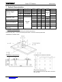
HMT070CB-C
Smart TFT Module
User’s Manual
Rev.
1.0
1.1
URL:
Prepared by:
Checked by:
Approved by:
Date:
Date:
Date:
Descriptions
Initial release
Refine description, add command table
www.topwaydisplay.com
www.topwaysz.com
Release Date
2011-12-10
2012-10-30
Document Name: HMT070CB-C Manual-Rev1.1.DOC
Page: 1 of 10
TOPWAY
Smart TFT Module
HMT070CB-C
Table of Content
1. General Information ....................................................................................................3
1.1
Highlight .....................................................................................................................3
2. Basic Specifications ...................................................................................................3
2.1
RS232 Interface Terminal (K1) ..................................................................................4
3. Absolute Maximum .....................................................................................................4
4. Electrical Characteristics ...........................................................................................4
4.1
DC Characteristics .....................................................................................................4
4.2
AC Characteristics .....................................................................................................5
4.3
Command Packet Format ..........................................................................................5
5. Functional Specification.............................................................................................5
5.1
Font Library Space.....................................................................................................5
5.2
Picture and Data Space .............................................................................................5
5.3
Display Coordinate.....................................................................................................5
6. Command Table ..........................................................................................................6
7. Optical Characteristics ...............................................................................................8
8. Precautions of Using LCD Modules...........................................................................9
9. Appendix ...................................................................................................................10
9.1
URL:
Bright/Dark Dots:......................................................................................................10
www.topwaydisplay.com
www.topwaysz.com
Document Name: HMT070CB-C Manual-Rev1.1.DOC
Page: 2 of 10
TOPWAY
Smart TFT Module
HMT070CB-C
1. General Information
TOPWAY HMT070CB-C is a Smart TFT Module. The onboard 32bit ARM processor act as
a graphic engine offer lots of outstanding high performance features. It could also simply the
host operation and increase reliability of the system. It is suitable for industry control,
instrumentation, medical electronics, power electric equipment, etc
1.1
-
Highlight
Wide viewing angle 7 inch TFT Display
800(RGB) x 480 pixels, 65k color
Wide range of single DC power supply
Wide operating temperature
RS232-C interface
High reliability resistive touch screen
Rich software instructions for graphics, text and picture operations
128MB Flash memory on board for preload picture or font library.
Instance call and show preloaded picture
ASCII and GB code for text display
Expandable font libraries
Sport double layer graphic and text display
Real time clock and buzzer feature
Adjustable backlight brightness
Industrial level structure and hardware design
Comply with ROHS.
2. Basic Specifications
Outline Dimension: 190.0x112.0x16.0(mm)
(refer to outline drawing)
Mounting Dimension: 179.8x101.9(mm) and 171.7x103.6(mm) (refer to outline
drawing)
Display Size: 7.0 inches
Resolution: 800*(RGB)*480
Color Depth: 16bits(RGB=565), 65k(65536) colors
Backlight Type: LEDs
User Interface: RS232-C (optional 3.3V UART)
Font Library: 32MB (support up to 60 Font Libraries)
Picture Library: 96MB (support up to 130 bmp pictures)
RTC: year, month, date, hour, minute, second, day of week
(up to year 2099)
Buzzer: Beep time and frequency could be adjusted by command
Touch Panel: resistive touch panel
URL:
www.topwaydisplay.com
www.topwaysz.com
Document Name: HMT070CB-C Manual-Rev1.1.DOC
Page: 3 of 10
TOPWAY
2.1
Smart TFT Module
HMT070CB-C
RS232 Interface Terminal (K1)
PIN No. PIN Name
I/O Description
P Power supply (DC9V~18V, DC12V is recommend)
1, 2
Vin
3
(NC)
No connection
4
Dout
O Data output from LCD module
5, 6
Din
I
Data Input to LCD Module
7, 8
GND
P Ground
Note.
- User data and commands transfer through this terminal
- Over ranged signal input will damage the module
please confirm the interface setting before applying the signal
- K1 signal level configuration
JP2
JP3
JP4
JP5 K1 signal
Open Open Close Close RS232-C Level (Default)
Close Close Open Open 3.3V TTL/CMOS Level
3. Absolute Maximum
GND=0V
Item
Power Voltage
Operating Temperature
Storage Temperature
Symbol
Vin
Top
Tst
Min.
6
-20
-30
Max.
24
70
80
Unit
V
°C
°C
Condition
No Condensation
No Condensation
Note: Any stresses exceeding the absolute maximum may cause unrecoverable damage to the LCD module.
4. Electrical Characteristics
4.1
DC Characteristics
Item
Power Voltage
Current
RS232-C input (low)
RS232-C input (high)
RS232-C output (low)
RS232-C output (high)
UART input (low)
UART input (high)
UART output (low)
UART output (high)
URL:
www.topwaydisplay.com
www.topwaysz.com
Symbol
VIN
Min.
9.0
Typ.
12.0
IVIN
-
230
IVIN
VDIN_RS_L
VDIN_RS_H
VDOUT_RS_L
VDOUT_RS_H
VDIN_TTL_L
VDIN_TTL_H
VDOUT_TTL_L
VDOUT_TTL_H
-3.0
+3.0
-3.0
+3.0
0
2.0
0
2.0
130
-
VIN=12V, Top=25℃, GND=0V
Max.
Unit Condition
18.0
V
Backlight on
mA
(Brightness=max.)
mA Backlight off
-15.0
V
MARK, logic 1
+15.0
V
SPACE, logic 0
-15.0
V
MARK, logic 1
+15.0
V
SPACE, logic 0
0.8
V
logic 0
3.3
V
logic 1
0.8
V
logic 0
3.3
V
logic 1
Document Name: HMT070CB-C Manual-Rev1.1.DOC
Page: 4 of 10
TOPWAY
Smart TFT Module
HMT070CB-C
4.2 AC Characteristics
Start bit
1
Data bit
8
Paraity bit None
Stop bit
1
Baud Rate 115200bps (default) (*1)
Note.
*1. Baud Rate could be adjusted by software in range of : 1200bps~115200bps
4.3 Command Packet Format
All commands are organized in packet with 4 data blocks:
Data block Data
Description
Sequence
1
0xAA
Packet header,1byte,fixed as 0xAA
2
(Command code)
Command code, 1byte
3
(Parameter or Data)
Parameter or Data. Maximum 500bytes.
4
0xCC 0x33 0xC3 0x3C Packet tail,4 bytes, fixed as 0xCC 0x33 0xC3 0x3C
5. Functional Specification
5.1 Font Library Space
Total 32M byte of flash memory is available for font library.
By default the following font library are preloaded:
- 4x ASCII (8x16,16x32,24x48,32x64)
- 2x GBK (Chinese,16x16,24x24 dots character)
- 2x GB2312 (Chinese,32x32,64x64 dots character)
5.2 Picture and Data Space
Total 96M byte of flash memory is available for BMP pictures (800x480, 16bit color) preload.
Where, user could assign 32M byte (max.) as custom data storage.
5.3 Display Coordinate
The top-left corner point is the origin (0, 0) of the display.
URL:
www.topwaydisplay.com
www.topwaysz.com
Document Name: HMT070CB-C Manual-Rev1.1.DOC
Page: 5 of 10
TOPWAY
Smart TFT Module
HMT070CB-C
6. Command Table
Type
Name
Code
Handshake
hand_shake
0x00
Draw pixels
Draw Lines
Draw Circles
Fill Circles
Draw
Rectangles
Fill
Rectangles
Display mode
Configuration
draw_rect_fg
0x59
draw_rect_bg
0x69
fill_rect_bg
0x5A
fill_rect_fg
0x5B
set_color
set_char_sp
Set_color_bg
set_color_fg
set_cursor_mode
read_fontlib
0x40
0x41
0x42
0x43
0x44
0x53
disp_char
0x54
disp_char_fg
0x55
set_textbox
0x45
Description
Respond “OK” as alive, and suffix
configuration and version
information
Draw pixels with background color
Draw piexls with foreground color
Draw lines with foreground color
Draw lines with background color
Draw circle
Fill circle
Draw rectangles with foreground
color
Draw rectangles with background
color
Fill rectangles with background
color
Fill rectangles with foreground
color
Set color palette
Set character spacing
Select and set background color
Select and set foreground color
Set cursor mode
Read font library information
Select font library and display
characters with appointed
background and foreground
colors
Select font and display characters
with foreground color
Set text box / close text box
clr_screen
0x52
Clear area/screen
disp_pic
save_pic
0x70
0xE2
cut_pic
0x9E
cut_pic_trans
0x9D
Display a full screen picture
Save a specific picture to Flash
Cut and paste part of a specific
picture/ Icon
Cut and paste part of a specific
picture/ Icon with transparent
mode
Download pictures
Download font libraries
Read touch code
Set touch code
Touch point coordinates upload
Touch panel calibration
Beep time and frequency control
64 degree backlight brightness
draw_pixel_bg
draw_piexl_fg
draw_line_fg
draw_line_bg
draw_circle
fill_circle
0x50
0x51
0x56
0x5D
0x57,0x01
0x57,0x03
Text display
Area
operation
Picture/Icon
display
Picture/Font
library load
download_pic
download_fontlib
read_touch_code
Touch panel
set_touch_code
operation
read_touch_coordiante
touch_calib
Buzzer Control buzzer_ctrl
Backlight
backlight_ctrl
URL:
www.topwaydisplay.com
www.topwaysz.com
0x72,0x00
0x72,0x01
0x78
0x98
0x72
0xe4
0x79
0x5F
Document Name: HMT070CB-C Manual-Rev1.1.DOC
Page: 6 of 10
TOPWAY
Smart TFT Module
control
RTC
RTC_adjust
RTC_read
RTC_disp
RTC_set
0xE7
0x9B,0x5A
0x9B,0x00
0x9B,0XFF
Work mode
Set_workmode
0xE0
configuration
Note.
For details, please refer to Software Manual.
URL:
www.topwaydisplay.com
www.topwaysz.com
HMT070CB-C
control
Date and time adjustment
RT clock upload
RT clock display in default mode
RT clock display mode set up
Baud Rate and system parameter
configuration
Document Name: HMT070CB-C Manual-Rev1.1.DOC
Page: 7 of 10
TOPWAY
Smart TFT Module
HMT070CB-C
7. Optical Characteristics
Item
Viewing Angle
(CR≥10)
Response Time
Contrast Ratio
Color Chromaticity
Luminance
Luminance
uniformity
Symbol
θL
θR
θT
θB
Tf
Tr
CR
WX
WY
L
YU
Condition
9 o’clock
3 o’clock
12 o’clock
6 o’clock
Normal
θ=0o
MIN.
60
60
40
60
400
0.26
0.28
-
TYP.
70
70
50
70
10
15
500
0.31
0.33
250
MAX.
20
30
0.26
0.38
-
70
75
-
UNIT
Note.
*2
degre
e
msec *3
msec
*1
cd/m2 *4
%
*4
Note:
*1. Definition of Contrast Ratio
The contrast ratio could be calculate by the following expression:
Contrast Ratio (CR) = Luminance with all pixels white / Luminance with all pixels black
*2 Definition of Viewing Angle
*3 Definition of response time
*4 Definition of Luminance Uniformity
Luminance uniformity (Lu)=
Min. Luminance form pt1~pt9 / Max Luminance
form Pt1~pt9
URL:
www.topwaydisplay.com
www.topwaysz.com
Document Name: HMT070CB-C Manual-Rev1.1.DOC
Page: 8 of 10
TOPWAY
Smart TFT Module
HMT070CB-C
8. Precautions of Using LCD Modules
Mounting
- Mounting must use holes arranged in four corners or four sides.
- The mounting structure so provide even force on to LCD module. Uneven force (ex. Twisted
stress) should not applied to the module. And the case on which a module is mounted should
have sufficient strength so that external force is not transmitted directly to the module.
- It is suggested to attach a transparent protective plate to the surface in order to protect the
polarizer. It should have sufficient strength in order to the resist external force.
- The housing should adopt radiation structure to satisfy the temperature specification.
- Acetic acid type and chlorine type materials for the cover case are not desirable because the
former generates corrosive gas of attacking the polarizer at high temperature and the latter
causes circuit break by electro-chemical reaction.
- Do not touch, push or rub the exposed polarizer with glass, tweezers or anything harder than HB
pencil lead. Never rub with dust clothes with chemical treatment. Do not touch the surface of
polarizer for bare hand or greasy cloth.(Some cosmetics deteriorate the polarizer.)
- When the surface becomes dusty, please wipe gently with absorbent cotton or other soft
materials like chamois soaks with petroleum benzene. Normal-hexane is recommended for
cleaning the adhesives used to attach front / rear polarizer. Do not use acetone, toluene and
alcohol because they cause chemical damage to the polarizer.
- Wipe off saliva or water drops as soon as possible. Their long time contact with polarizer
Operating
- The spike noise causes the mis-operation of circuits. It should be within the ±200mV level (Over
and under shoot voltage)
- Response time depends on the temperature.(In lower temperature, it becomes longer.)
- Brightness depends on the temperature. (In lower temperature, it becomes lower.) And in lower
temperature, response time(required time that brightness is stable after turned on) becomes
longer.
- Be careful for condensation at sudden temperature change. Condensation makes damage to
polarizer or electrical contacted parts. And after fading condensation, smear or spot will occur.
- When fixed patterns are displayed for a long time, remnant image is likely to occur.
- Module has high frequency circuits. Sufficient suppression to the electromagnetic interference
shall be done by system manufacturers. Grounding and shielding methods may be important to
minimized the interference
Electrostatic Discharge Control
- Since a module is composed of electronic circuits, it is not strong to electrostatic discharge.
Make certain that treatment persons are connected to ground through wrist band etc. And don’t
touch interface pin directly.
Strong Light Exposure
- Strong light exposure causes degradation of polarizer and color filter.
Storage
- When storing modules as spares for a long time, the following precautions are necessary.
- Store them in a dark place. Do not expose the module to sunlight or fluorescent light. Keep the
temperature between 5°C and 35°C at normal humidity .
- The polarizer surface should not come in contact with any other object. It is recommended that
they be stored in the container in which they were shipped.
Protection Film
- When the protection film is peeled off, static electricity is generated between the film and
polarizer. This should be peeled off slowly and carefully by people who are electrically grounded
and with well ion-blown equipment or in such a condition, etc.
- The protection film is attached to the polarizer with a small amount of glue. If some stress is
applied to rub the protection film against the polarizer during the time you peel off the film, the
glue is apt tore main on the polarizer. Please carefully peel off the protection film without rubbing
it against the polarizer.
- When the module with protection film attached is stored for a long time, sometimes there
remains a very small amount of glue still on the polarizer after the protection film is peeled off.
- You can remove the glue easily. When the glue remains on the polarizer surface or its vestige is
recognized, please wipe them off with absorbent cotton waste or other soft material like chamois
soaked with normal-hexane.
Transportation
- The LCD modules should be no falling and violent shocking during transportation, and also
should avoid excessive press, water, damp and sunshine.
URL:
www.topwaydisplay.com
www.topwaysz.com
Document Name: HMT070CB-C Manual-Rev1.1.DOC
Page: 9 of 10
TOPWAY
Smart TFT Module
HMT070CB-C
9. Appendix (Inspection items and criteria for appearance defect)
9.1
Bright/Dark Dots:
Defect Type
Specification
Major
Minor
Bright Dots
N≤ 2
●
Dark Dots
N≤ 3
●
Total Bright and Dark Dots
N≤ 4
●
Note: 1. The definition of dot: The size of a defective dot over 1/2 of whole dot is regarded as
one defective dot.
2. Bright dot: Dots appear bright and unchanged in size in which LCD panel is
displaying under black pattern.
3. Dark dot: Dots appear dark and unchanged in size in which LCD panel is displaying
under pure red, green, blue pattern.
URL:
www.topwaydisplay.com
www.topwaysz.com
Document Name: HMT070CB-C Manual-Rev1.1.DOC
Page: 10 of 10