1
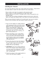
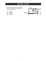
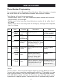
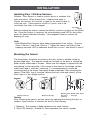
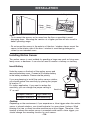
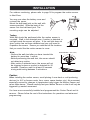
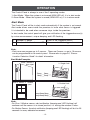
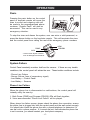
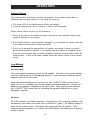
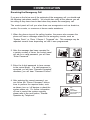
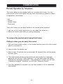
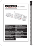
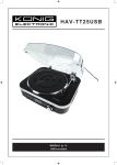
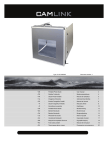
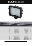
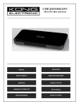
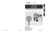
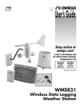
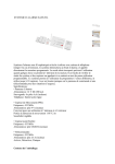
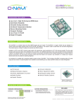
SEC-ALARM200
WIRELESS ALARM SYSTEM
-1-
Safety precautions:
CAUTION
To reduce risk of electric shock,
this product should ONLY be
opened by an authorized technician
when service is required. Disconnect the product from mains and ther
equipement if a probleem should occur. Do not expose the product to
water or moisture.
RISK OF ELECTRIC SHOCK
DO NOT OPEN
Maintenance:
Clean only with a dry cloth. Do not use cleaning solvents or
abrasives.
Warranty:
No guarantee or liability can be accepted for any changes and
modificatieons of the product or damage caused due to incorrect use
of this product.
General;
Designs and specificatiën are subject to change without notice.
All logos brands and product names are trademarks or registered
trademarks of their respectieve holders and are hereby recognized as
such.
Attention:
This product is marked with this symbol. It means that used
electrical and electronic products should not be mixed with
general household waste. There is a separate collectors
systeem for these products.
Copyright ©
-2-
INTRODUCTION
7
8
12
]
11
1
2
10
9
4
3
5
6
15 16 17
14
18
13
19
1.
2.
3.
4.
5.
6.
7.
8.
9.
10.
Zone LEDs
Numeric Keypad
Arm button
Status button
Mute button
Panic button
Power LED
Arm LED
Program LED
System Low Battery LED
11. Built-in Siren and Speaker
12. Antenna
13. Programming button
14. Buzzer Mode Selector
15. Phone Jack for external phone
16. Line Jack for telephone line
17. Adapter socket
18. Battery Compartment
19. Language Selector (only available for
models with multiple languages)
-3-
INSTALLATION
Installing the Console
You must first determine where the control panel will be located. Please follow
the criteria below to select the ideal location for the control panel.
- Place it within a few feet of an electrical outlet and phone jack
- Place it where it is easily accessible by you and other users
- Place it away from any doors or windows which could be accessed by nonintended users
- Place it away from extreme temperature sources such as oven, stove and
away from large metal objects which could affect the wireless performance
After you have selected a location for the control panel, you are now ready to
connect all the necessary wires and ready to power up the unit.
1. Plug in the AC adapter to a nearby electrical
outlet and plug the other end to the socket
labeled “DC 12V” on the back of the control
Panel. You should hear 3 beeps and
“System Phone Failure” indicating the
phone line is not connected. PWR, ARM
and PROG LEDs should be flashing, LO
BATT LED should be on.
2. Remove the battery cover on the bottom
of the control panel with a Phillips screw
driver, and insert 4 AAA alkaline batteries
into the battery holder (note the polarity).
After inserting the batteries, the LO BATT
LED should be off.
3. Connect the phone line from the telephone
jack to the back of the control panel where
it marks “LINE”. PWR will stay on and
PROG LED will stop flashing.
4. [OPTIONAL] If you have another telephone
that will be using the same telephone jack,
you may connect this telephone to "PHONE"
outlet of the the control panel by a phone
cord. (not provided).
5. Rotate the antenna to the upright position to
ensure the best signal reception.
-4-
1
4
3
2
INSTALLATION
6. For models with multiple languages,
select the desired language based
on the setting below.
[1][2][3][4]-
German
Spanish
French
English
Language
selector
-5-
INSTALLATION
Phone Number Programming
You can program up to 5 Emergency Phone Numbers. When the system is in panic,
the control panel will call these phone numbers and announce its status.
The following will need to be programmed:
- Phone memory (from 1 to 5), this is where the phone numbers will be stored
- Phone number, up to 29 digits.
- Redial count, this is how many times that phone number will be called, from 1
to 9 times.
- Repeat count, this is how many times the emergency message will be repeated,
from 1 to 9 times.
Step
Keys
Function
Description
Note
Enter master password to
Enter
Programming programming mode
mode
3 beeps for valid
password. 1 long beep
for invalid password.
You will hear [Enter
phone memory].
1
[PROG]
[MPIN]
2
[1]
Select phone
number
programming
3
[1] to [5]
Enter phone
memory
During emergency, phone
memory 1 will be called first,
then phone memory 2, 3, 4, and
5. So phone memory 1 has
higher priority.
4
[Phone
number]
+ [Arm]
Enter phone
number
Phone number can be up to 29
digits.**
You will hear [Enter
Redial].
5
[1] to [9]
+ [Arm]
Enter Redial
count
Redial is the number of times
that phone number will be
called. Each phone number
can have a different redial
count, from 1 to 9 times.
You will hear [Enter
Repeat].
6
[1] to [9]
+ [Arm]
Enter Repeat Repeat is the number of times You will hear [Phone
that voice emergency message Accepted] indicating the
count
will be played, from 1 to 9 times.
It is recommended to set up
the repeat time to 5 or more.
phone number and its
settings have been
programmed successfully.
**Note:
You may enter a 3-second pause between digits by pressing [Mute] if needed.
You may also enter consecutive multiple pause periods. For example, you may
enter a phone number: (123)-456-7890 [Mute] 1234. After the phone number
(123)-456-7890 is dialed, it will wait for 3 seconds, then dial 1234, which can be
a password to a paging system, or an access code for a phone dialing system.
-6-
INSTALLATION
Phone Number Programming
You can program up to 5 Emergency Phone Numbers. When the system is in panic,
the control panel will call these phone numbers and announce its status.
The following will need to be programmed:
- Phone memory (from 1 to 5), this is where the phone numbers will be stored
- Phone number, up to 29 digits.
- Redial count, this is how many times that phone number will be called, from 1
to 9 times.
- Repeat count, this is how many times the emergency message will be repeated,
from 1 to 9 times.
Step
Keys
Function
Description
Note
Enter master password to
Enter
Programming programming mode
mode
3 beeps for valid
password. 1 long beep
for invalid password.
You will hear [Enter
phone memory].
1
[PROG]
[MPIN]
2
[1]
Select phone
number
programming
3
[1] to [5]
Enter phone
memory
During emergency, phone
memory 1 will be called first,
then phone memory 2, 3, 4, and
5. So phone memory 1 has
higher priority.
4
[Phone
number]
+ [Arm]
Enter phone
number
Phone number can be up to 29
digits.**
You will hear [Enter
Redial].
5
[1] to [9]
+ [Arm]
Enter Redial
count
Redial is the number of times
that phone number will be
called. Each phone number
can have a different redial
count, from 1 to 9 times.
You will hear [Enter
Repeat].
6
[1] to [9]
+ [Arm]
Enter Repeat Repeat is the number of times You will hear [Phone
that voice emergency message Accepted] indicating the
count
will be played, from 1 to 9 times.
It is recommended to set up
the repeat time to 5 or more.
phone number and its
settings have been
programmed successfully.
**Note:
You may enter a 3-second pause between digits by pressing [Mute] if needed.
You may also enter consecutive multiple pause periods. For example, you may
enter a phone number: (123)-456-7890 [Mute] 1234. After the phone number
(123)-456-7890 is dialed, it will wait for 3 seconds, then dial 1234, which can be
a password to a paging system, or an access code for a phone dialing system.
-7-
INSTALLATION
Note:
- It’s not recommended to program 911, fire station or any emergency services
phone numbers into any of the phone memories without their approvals.
- Ensure to program a valid phone number and write down the programmed
phone number on the System Setting Information provide on the back of this
user's instructions.
- You may quit programming by pressing [PROG] button at any time.
- If no phone number is programmed, the ARM LED will continue to flash.
Testing Phone Numbers:
After you have programmed all the phone numbers, you should verify you have
programmed the phone numbers correctly. This can be done by triggering the
alarm silently by entering the duress password, so it dials to the programmed
phone numbers without sounding the alarm.
Note:
You must inform the recipients of the programmed phone numbers, so they know
what to expect when they receive the phone call from the control panel during an
emergency. These recipients should know the password to your control panel if
you expect them to have remote access of your control panel. For more information regarding receiving the emergency call, please refer to page 23.
1. Press [Arm], you should hear beeping from the control panel.
2. Press [3838]. Beeping will stop, and the control panel will start to dial the first number.
3. The called party should receive the call. Pick up the call and say “Hello”, an
emergency message “System Panic” will be played. If the programmed phone
doesn’t ring, ensure the phone number is programmed correctly, or reprogram
this phone number again.
4. After the emergency message has been played for several times (depending on
how many times it was programmed), the called party will hear “Enter Password”.
5. Enter either the master password or secondary password. If the correct
password is accepted, you will hear “Password Accepted”, otherwise, you will
hear “Password Failure”.
6. Press [0][#] on the telephone to hang up.
7. The control panel will start to dial the next programmed phone number.
Note:
- Refer to page 23 [Receiving the Emergency Call] for more info on how to react
to an emergency call.
- The password is treated as a confirmation of the emergency message. Once a
valid password is entered, the control panel will not call that number again, it
will proceed to the next number.
- If any one of the called parties disarms the control panel, the control panel will
not continue to dial the remaining phone numbers.
- After calling all the programmed phone numbers, the control panel will be back
to the previous operation mode.
-8-
INSTALLATION
Installing Door / Window Sensors
Window / Door Sensor is used to monitor doors or windows that
open and close. When these doors / windows are open or
closed, the sensors will transmit a signal to the control panel to
notify the user. These sensors consist of 2 parts, one is the
transmitter, the other is the magnet.
Transmitter
Magnet
Before installing the sensor, remove the battery isolator by pulling out the yellow
tab. Once the isolator is removed, the corresponding zone LED on the control
panel will flash and buzzer will beep. If the magnetic contact is closed, the
beeping will stop.
Note:
- Both Window/Door Sensors have been programmed at the factory. They are
Zone 1 Sensor 1 and Zone 2 Sensor 1. Trigger the sensor and listen to the
beeping and zone LED to determine which one is zone 1 and which is zone 2.
Mounting the Sensor
The transmitters should be mounted on the door frame or window frame by
double sided tape. The magnet should be mounted on the door or window by
either double sided tape or screws. Make sure the magnet is aligned with the
red marking on the transmitter. If the surface of the frame is flat enough, doublesided foam tape is sufficient, otherwise, it is recommended to screw the
mounting plate to the frame, then apply double sided tape. After mounting the
sensor, if the AAA+ logo is inverted, remove the front cover and rotate it so the
AAA+ logo is in the upright position.
Magnet on the left
Magnet on the right
Mounting plate Double-sided Sensor
foam tape
and screws
(optional)
Testing:
After mounting the sensor, test the sensor by opening and closing the door or
window. Open the door or window will result in the followng:
1. Beeping - The number of beep represents the zone number.
2. Zone LED flashing - Number of flash represents the sensor number.
-9-
INSTALLATION
2. Single flash
1. Beep___Beep___
Beep___Beep___
............
Note:
- Try to mount the sensors as far away from the floor as possible to avoid
damaging them. Mounting the sensors at a higher position will also result in
better operating range.
- Do not mount the sensor to the exterior of the door / window, always mount the
sensor to the interior side of the door / window to avoid being damaged or
stolen by non-intended users.
Installing Motion Sensor
The motion sensor is most suitable for guarding a large area such as living room,
family room, or bedroom. It can also be used to monitor a hallway or stairway.
Insert Battery
Undo the screw on the back of the motion sensor and
remove the battery cover. Connect a 9V alkaline battery
to the battery connector. Please note the polarity.
If you are planning to install the motion sensor outdoor,
you should reduce the sensitivity by placing the jumper
at location “2”.
For indoor application, if you want to reduce the
sensitivity, you can change the jumper setting to
Sensitivity
“2” as well.
Jumper Location 1
Jumper Location 2
High Sensitivity
Low Sensitivity
Caution:
Depending on the environment, if you experience a false trigger when the motion
sensor is placed outdoors, you should relocate it or even place it indoors. Wind
blowing at a tree, or direct sunshine could cause a false trigger. Therefore, if the
location at where the motion sensor is mounted could cause a false trigger, you
should change the mounting location for such sensor.
10––-13
INSTALLATION
For outdoor monitoring, please refer to page 30 to program the motion sensor
to Alert Zone.
You may now close the battery cover and
re-insert the screw.
Mount the ball-head joint on the wall with
screws provided. Slide the back of the
sensor into the ball-head joint. The
mounting angle can be adjusted.
Testing
Walk test should be performed after the motion sensor is
mounted. Walk in the detected area, if motion is detected, a
red light inside the sensor will glow. If the red light does not
glow, motion has not been detected and you may need to
re-position the sensor. Ensure you walk test all the locations
that you would like the motion sensor to cover.
Note:
- Perform the walk test after you have inserted the
battery for more than 1 minute.
- Before performing the walk test, the sensor should
not detect any motion.
- After motion is detected once, the sensor will not
be triggered unless no motion is detected for 20
seconds. Therefore, wait for at least 20 seconds
during walk testing between 2 activations.
DETECTING AREA:
14
(Unit = meter)
1.2M
55°
55°
11°
12
10
8
6
22°
27°
22°
4
2
M
12°
SENSOR
0
1
2
3
4
5
6
7
8
9
10
11
12
13
Caution:
When installing the motion sensor, avoid placing it near heat or cold producing
devices (i.e. A/C or furnace vents, fans, ovens, space heaters, etc). Air movement,
especially caused by changes in temperature may trigger the Motion Sensor and
cause false alarms. Please carefully test your Motion Sensor so that it will only be
triggered by wanted movement.
You have now successfully installed and programmed the Control Panel and its
sensors. Please follow the rest of the instructions for operations and advanced
programming.
- 11 -
OPERATION
The Control Panel is always in one of the 2 operating modes:
1. Alert Mode - When the system is not armed (ARM LED off), it is in alert mode.
2. Alarm Mode - When the system is armed (ARM LED on), it is in alarm mode.
Alert Mode
The Control Panel will be in alert mode automatically if the system is not armed.
Alert mode allows users inside the premises to know what sensor is triggered.
It is intended to be used when someone stays inside the premises.
In alert mode, the control panel will give you notification of the triggered sensor(s)
by voice announcement, unique beeping and LED flashing.
1
Number of beeps
Zone of the triggered sensor
2
Number of flashes of zone LED
Sensor number of the triggered sensor
Note:
- Each zone can program up to 2 sensors. There are 5 zones, so up to 10 sensors
can be programmed to the control panel. Please refer to page 34, "Sensor
Location Selection Guide" for detail information.
Alert Mode Examples
Zone 1 Sensor 1
door open
2. Single flash
1. Beep___Beep___
Beep___Beep .....
Zone 3 Sensor 2 window
open
2. Double flash
1.
Beep Beep Beep___
Beep Beep Beep___
Note:
-For Door / Window sensor, alert notification (beeping and LED flashing) will
continue until the sensor is in closed position, i.e. closing the window or door.
-For Motion Sensor, the alert notification (beeping and LED flashing) will last for 20
seconds for every detected movement.
-–
12 -
OPERATION
Mute
When the alert beeping becomes undesired, you can terminate the beeping in 3
different ways:
1. Mute button - Manual mute by pressing the
mute button
Pressing the mute button will temporary
disable the beeping for all the activated
sensors. For example, if a window with a
window sensor will be open for a long period
of time, the continuous beeping may become
undesired. Pressing the mute button will
temporary disable the beeping for this
sensor only, it will still beep if other sensors
are triggered. This sensor will beep again
if this window is closed, and then opened.
Mute Button
Buzzer Mode Selector
2. Change the buzzer mode - Disable Beeping
The beeping can be disabled for all
zones by changing the buzzer mode
selector.
- If the buzzer mode selector is at "I", beeping is enabled.
- If the buzzer mode selector is at "II", beeping is disabled.
If beeping is disabled, all sensor alert beeping will be disabled, however, the
voice announcement and LED flashing will still function.
3. Enable Auto-Mute in Advanced Programming
If this feature is enabled for that zone, beeping will be terminated automatically
after 15 seconds . Refer to "Advanced Programming" - Auto Mute" on page 29
for more information on how to enable this feature.
- 13 -
OPERATION
System Status
The control panel continuously monitors the system status as well as all the
sensors status. It will monitor occurrences such as triggered sensors, low
battery sensors, malfunction sensors, or phone line failure etc.
In order to check the system status, user can press the “Status” button on the
control panel, voice announcement will be made regarding the system and
sensor status. When the “Status” button is pressed, you will be notified if any of
the following events is occurring:
-
System armed or disarmed
Any triggered sensors
Any sensors with low battery warning
Any sensors with failure warning
Phone line failure
Refer to page 20 for more details regarding system failures.
Arming the System
You should arm the system when you are the last person to leave the house. By
arming the system, the control panel will call the preprogrammed emergency
phone numbers and the siren will sound when break-in occurs.
Caution: Only arm the system when nobody is expected to be inside the premises.
When someone is expected to be within the premises, the system should not be
armed.
To arm the system, follow the procedures below:
Exit delay 45 seconds
OR
Beep Beep
1. Press [Arm] on the control 2. Leave the premises
panel or keychain remote.
within 45 seconds.
45 seconds later
ARM LED on. System
Armed
3. After 45 seconds.
System will be armed.
1. Press [Arm] button on the control panel when no sensors are triggered.
You can also use the keychain remote to arm the system by pressing arm
button on the remote.
- 14 -
OPERATION
Note:
- The control panel cannot be armed if there are triggered sensors. Make sure
all sensors are in closed position, i.e. (close all doors, windows, no movement
should be detected etc).
- The control panel can be armed if there are sensors with low battery or failure
warning.
2. After pressing the “ARM” button, the “ARM” LED will flash and you will have 45
seconds to leave the premises, this is called the exit delay. You will hear
beeping during the exit delay interval. The beeping rate will change from slow
to fast, the faster the beep rate, the less time you have left to leave the premises
before the siren sounds.
3. When the exit delay expires, the control panel will announce “System Armed”,
beeping will stop and the ARM LED will be on steadily. This indicates the
system is now armed.
Note:
The control panel can also be armed remotely when nobody is home, with a touch
tone phone. Please refer to “Remote Operation by Telephone” on page 24.
Disarming the system
If a sensor is triggered while the control panel is armed, such as entering a house
with an armed control panel, an entry delay will be triggered. User is allowed to
disarm the control panel during the 30-second entry delay. If the control panel is
not disarmed within 30 seconds, siren will sound immediately and emergency
calls will be made. To disarm the control panel, follow the instructions below.
Entry delay 30 seconds
Beep Beep
Arm LED flashes
Beep Beep
OR
1. Entering the premises 2. Enter password within
will trigger the entry
30 seconds or press the
delay.
disarm button on the
keychain remote.
Arm LED off
System
Disarmed
3. Once the system is
disarmed, the Arm
LED will be off.
1. During the entry delay, the system will beep for 30 seconds, the ARM LED will
flash during this entry delay interval. The faster the beep, the less time you
have left to disarm the control panel before the siren sounds.
- 15 -
OPERATION
2. You must enter a valid password, either the Master Password, or Secondary
Password to disarm the system before entry delay expires. The system can
also be disarmed by pressing button 3 on the keychain remote.
3. When a valid password is entered, you will hear “System Disarmed” and the
entry delay beeping will stop, the ARM LED will be off.
Note:
- The control panel can also be disarmed remotely when nobody is home, with a
touch tone phone. Please refer to “Remote Operation by Telephone” on page 24.
- If 3 consecutive incorrect passwords are entered, alarm will sound immediately,
the control panel will be in panic mode, and start calling the emergency phone
numbers.
Disarming a triggered control panel
If "System Panic" is announced from the control panel after it has been disarmed,
that means the alarm was triggered when it was in armed mode. Follow the
procedures below to set the control panel back to standby mode.
1. If the alarm was caused by sensor(s), there will be flashing LEDs and
beeping indicating which sensor(s) triggered the alarm. You may want to
check the condition of the triggered sensor(s), the sensor(s) may be damaged
if there were break-ins.
2. You need to reset the sensor manually by triggering it twice, i.e. open and
then close a door / window sensor, or walk in front of the motion sensor. The
LED representing that sensor will stop flashing after it receives the signal
from the sensor.
3. You must now enter the password again on the control panel or press the
disarm button on the keychain remote, as an acknowledgement of the alarm
event. This will set the control panel back to standby mode.
Disarming under Duress
If you are forcibly compelled to disarm the control panel, you may enter the Duress
Password. Entering the duress password will terminate the entry delay, i.e. no
more entry delay beeping. But the control panel will silently call the emergency
phone numbers for help. The called party will hear the voice announcement
“System Panic”.
Note:
- The default duress password is [3838].
- 16 -
OPERATION
Panic
Pressing the panic button on the control
panel or keychain remote will cause the
siren to sound and outgoing calls will
be made to the preprogrammed phone
numbers, “System Panic” will also be
announced. This can be used in any
emergency situation.
OR
To stop the siren and disarm the system, user can enter a valid password, or
press the disarm button on the keychain remote. This will terminate the siren
and the control panel from calling the rest of the emergency phone numbers.
ARM
DISARM
PANIC
AUX
- Control other Skylink receiver
such as Garage Door Receiver
System Failure
Control Panel constantly monitors itself and its sensors. If there are any trouble
conditions, the control panel will advise the user. These trouble conditions include:
- Phone Line Failure
- Sensor Failure (loss of supervisory signal)
- Low Battery – Control Panel
- Low Battery – Sensors
Phone Line Failure
When the phone line is disconnected or malfunctions, the control panel will
instantly notify the user by:
1. Both Power [PWR] and Program [PROG] LEDs will flash together;
2. Voice announcement “Phone Line Failure” will be played.
When phone line failure occurs, please check the phone line connection, ensure
the phone line is plugged into both the control panel and the wall socket securely.
You should also check the phone line with a normal telephone to determine if it
can dial out to a phone number. If it cannot dial out, that indicates the phone line
is not in service, you should contact your local phone company.
- 17 -
OPERATION
Sensor Failure
The control panel constantly monitors its sensors, if the control panel fails to
communicate with any sensors, it will notify the user by:
1. The zone LED of the failed sensor will be on steadily;
2. Voice announcement “zone X sensor Y failure” will be played.
When sensor failure occurs, try the following:
1. Check if the sensor is located at where it should be, and whether there is any
physical damage to the sensor.
2. If the failed sensor is not physically damaged, try to activate the sensor and see
if the control panel reacts to such activation.
3. If not, try to remove the sensor from its location, and bring it closer to control
panel and activate the sensor. It is possible that the sensor is installed too far
from the control panel and it cannot establish a steady communication with the
control panel. If this is the case, please install the sensor closer to the control
panel.
Low Battery
Control Panel
The control panel is powered mainly by the adapter. However, during power outage,
it will be powered by the 4 AAA backup batteries. Under standby conditions, these
batteries can last for 48 hours.
When the backup batteries are running low, the “LO BATT” LED on the control
panel will be on, indicating you should replace the backup batteries. Ensure all 4
batteries are replaced altogether at the same time. After replacing the batteries,
the “LO BATT” LED should be off, indicating the backup batteries are in good
operating condition.
Sensors
All of the sensors are battery powered. Depending on the operating condition and
environment, the battery life varies from 9 months to 2 years. 9V alkaline battery is
used for the motion sensor, the battery life is approximately 9 months. Door /
Window Sensor operates on a Lithium CR-2032 battery, with battery life of approximately 2 years.
- 18 -
OPERATION
When the sensor is running low in battery, the sensor will send a wireless low
battery signal to the control panel. The zone LED representing that sensor will be
on steadily, indicating sensor(s) in that zone is in trouble condition. Control Panel
will also have an announcement to advise the user the trouble condition is low
battery, such as “zone X sensor Y low battery”, where X and Y represent the zone
and sensor number. Please replace the battery of that sensor.
Keychain Remote
The battery of the keychain remote (Alkaline, Type 23A, 12V) needs to be replaced
when either one of the followings occurs:
1. The LED on the keychain doesn’t flash or on when a key is pressed; or
2. The operating range starts to decrease.
To replace the battery:
1. Undo the two screws on the back of the transmitter.
The bottom case will then come off.
2. Using a small screwdriver or pen, pry out the old
battery from one end.
3. Place the new battery in position. A diagram in the
battery compartment indicates which end is positive
and which is negative.
-
4. Close the battery cover and reinsert two screws.
+
- 19 -
COMMUNICATION
Receiving the Emergency Call
If you are on the list as one of the recipients of the emergency call, you should read
the following instructions carefully. You should also notify all the persons you will
be calling so they know how to react when they receive the emergency call.
The control panel will call you when there are emergencies such as break-ins,
smoke, fire events, or someone at home needs assistance.
1. When the phone rings at the calling location, the person who answers the
phone will hear a message related to the emergency events, such as
“System Panic”, or “Zone 1 Sensor 1 Triggered” etc. This message may be
repeated several times depending on how it was programmed.
2. After the message has been repeated for
a certain number of times, the control panel
will ask for a valid password, you will hear
“Enter Password”.
3. Enter the 4-digit password to have access
to the control panel. If a valid password is
accepted, you will hear “Password Accepted”,
otherwise, you will hear “Password Failure”.
Zone 1
Sensor 1
Triggered
Enter
Password
4. After entering the correct password, you
can follow the “Phone Command” instructions to perform the required tasks, such
as disarm, turn on / off devices or check the
system status etc. For further information
of how to control the system remotely,
please refer to the next section, "Remote
Operation by Telephone".
- 20 -
-Arm
-Disarm
-Check status
-Control lighting etc.
-Disconnect
COMMUNICATION
COMMUNICATION
Remote Operation by Telephone
The control panel can be operated while you are away from home. You can
have access to the control panel with any touch tone phone to perform a variety
of operations, listed below.
- Arm
- Disarm
- System status
- Disconnect
There are 2 ways you can have access to the remote phone operation:
1. You can call the control panel when you are away from home; or
2. When the control panel calls you during emergency.
To access the control panel away from home
Calling in when you are away from home
1. Call your home phone number, or the number that the phone line of the control
panel is connected to.
2. Hang up after the second ring.
3. Wait at least 10 seconds, but not more than 40 seconds, then call the phone
number again.
4. The control panel will pick up the phone call and request for a valid user
password, you will hear “Enter Password”. You can enter either the Master
Password or Secondary Password. If the password is correct, you will hear
“Password Accepted”, otherwise, you will hear “Password Failure”.
5. Once the password is accepted, you can have access to all the operations
listed below.
- 21 -
COMMUNICATION
Table 1: Remote Phone Operations
SYSTEM OPERATION
PHONE COMMAND
DESCRIPTION
Check system status
[8]+[#]
You will hear system status announcement
Arm
[7]+[#]
You will hear [System Armed]
Disarm
[9]+[#]
You will hear [System Disarmed]
Disconnect
[0]+[#]
Phone line disconnect
- 22 -
ADVANCED PROGRAMMING
Advanced Programming allows users to customize the control panel to react
differently under different conditions. Features such as:
-
When a sensor is triggered, the control panel can beep or alarm
Beeping can be terminated automatically after a fixed period of time for some sensors
Some sensors can be programmed to beep only, never alarm
When a door is open, turn lights on
Program additional sensors and remotes
Programming Summary
COMMAND
DESCRIPTION
[PROG] + [1]
Program Phone Numbers
[PROG] + [2]
Program Password
[PROG] + [3]
Learn Sensors
[PROG] + [4]
Learn Keychain
[PROG] + [5]
Beep / Alarm Setting
[PROG] + [6]
Auto Mute Setting
[PROG] + [7]
Event Trigger Setting
[PROG] + [8]
Alert Zone (Bypass) Setting
[PROG] + [9]
Erase Sensors
[PROG] + [0]
Erase Keychain or Keypad Transmitters / Control Modules
Follow the instructions below to have access to Advanced Programming.
Beep / Alarm
User can customize the audio warning so that when a sensor is triggered, the
control panel may beep or alarm may sound instantly. Depending on whether the
control panel is armed or disarmed, the audio warning is different.
System Disarmed (Alert Mode)
If a zone is set to “Beep”, the control panel will beep when a sensor is triggered,
until the sensor is deactivated. Motion Sensor activation will not cause any
beeping unless the zone for the motion sensor is programmed as a "Bypass
Zone" (see page 30)
If a zone is set to “Alarm”, alarm will sound instantly when a sensor is triggered.
Alarm will stop when the sensor is deactivated, or reaches a 3-minute time out period.
-–
23 -
ADVANCED PROGRAMMING
System Armed (Alarm Mode)
If a zone is set to “Beep”, the control panel will give entry / exit delay.
If a zone is set to “Alarm”, the siren will sound immediately without entry delay
- Alarm Mode (System Armed): If a sensor is triggered (i.e. opening a door) with
the alarm setting on, the siren will sound immediately without entry delay, it is
called “Instant Alarm”. The siren will not stop until the siren timeout or a valid
password is entered. Control panel will call the emergency phone numbers to
notify the users of the alarm situation.
When a sensor is triggered, there are 4 options:
ZONE SETTING
OPERATING MODE
BEEP
ALARM
Disarmed (Alert)
1) Beep
2) Alarm sounds immediately
Armed (Alarm)
3) Entry / Exit Delay
4) Alarm sounds and calls
preprogrammed phone
numbers immediately
Factory Default: All zones were programmed to Beep at the factory.
Y
-
Caution:
It is not recommended to program an outdoor sensor to Alarm mode, which may cause
false alarm. For outdoor sensors, they should be programmed into an Alert Zone,
please refer to page 30 for details.
–
- 24 -
ADVANCED PROGRAMMING
Follow the procedures below to program the beep / alarm setting.
Step
Keys
Function
Description
Note
1
[PROG]
[MPIN]
3 beeps for valid password.
Enter Programming Enter master
password to
1 long beep for invalid
mode
programming mode password.
2
[5]
Select Beep /
Alarm Setting
3
Set to Beep:
[1] to [5]
4
[PROG] when Terminate programming mode.
finished.
Select which
zone you would
like to Beep or
Set to Alarm: Alarm.
[6] to [0].
BEEP
After [5] is entered, some zone
LEDs will flash or stay on.
This indicates whether that
zone is set to beep or alarm.
Refer to the
diagram below to
select the appropriate setting.
PROG LED will be off, and
you will hear 3 beeps.
ALARM
This row :
Buttons for Beep
Zone 1 Button [1] Button [6]
Zone LED : Flash
Zone 2 Button [2] Button [7]
Zone 3
Button [3]
Button [8]
Zone 4 Button [4] Button [9]
Zone 5
Button [5]
If Alarm is set for that zone,
that zone LED will be on. If
Beep is set, the LED will
flash. You are allowed to
make multiple changes before
terminating programming
mode.
This row :
Buttons for Alarm
Button [0]
Zone LED : ON
Example:
If you would like to change the setting for zone 5 from “Beep” to “Alarm”, simply
press [0] at step 3.
This will change the zone 5 setting to “Alarm”.
- 25 -
ADVANCED PROGRAMMING
Auto Mute
When a sensor is triggered in alert mode, audio warning will be emitted, either
beep or alarm. For example, if a door is opened, the beep will not stop until the
door is closed. If the door is open for 2 hours, the beep will go on for 2 hours.
There are times that this is not desired. With the auto mute feature enabled, the
beep will go on for only 20 seconds. After that, even if the sensor remains open,
the beep will stop only the zone LED will flash to indicate the sensor is triggered.
Beep will go on again if the sensor is closed and opened again.
Note: Auto Mute only functions when the control panel is in alert mode (disarmed).
If the control panel is in alarm mode (armed), a triggered sensor will result in
entry delay or instant alarm.
Factory Default: This feature was disabled for all zones at the factory.
To enable auto mute feature, follow the instructions below.
Step
Keys
Function
Description
Note
Enter master
3 beeps for valid
password to
password. 1 long beep
programming mode for invalid password.
1
[PROG]
[MPIN]
Enter Programming mode
2
[6]
Select Auto Mute
Enable / Disable
3
Select which
Refer to the diagram
Disable
Auto Mute: zone you would below to select the
like to enable /
appropriate setting.
[1] to [5]
disable auto mute.
Enable
Auto Mute:
[6] to [0].
4
[PROG]
when
finished.
After [6] is entered, some
zone LEDs will flash or
stay on. This indicates
whether Auto Mute is
enabled or disabled.
Terminate
programming
mode.
If auto mute is enabled,
that zone LED will be on.
If it is disabled, the LED
will flash. You are allow
to make multiple changes
before terminating
programming mode.
PROG LED will be off, and
you will hear 3 beeps.
- 26 -
ADVANCED PROGRAMMING
This row :
Buttons to
Disable Auto Mute
ENABLE
DISABLE
AUTO MUTE AUTO MUTE
Zone 1 Button [1]
Button [6]
Zone 2 Button [2]
Button [7]
Zone 3 Button [3]
Button [8]
Zone 4 Button [4]
Button [9]
Zone 5 Button [5]
Button [0]
Zone LED : Flash
This row :
Buttons to
Enable Auto Mute
Zone LED : ON
Alert Zone (Bypass Zone)
As explained earlier, the control panel can operate in 2 different modes, 1) Alert
Mode, 2) Alarm Mode. In alarm mode, when a sensor is triggered, the control
panel will either give a 30 seconds entry delay, or siren will sound immediately
(with instant alarm). However, there are sensors that you do not want to trigger
the alarm when the system is armed. Such as an outdoor sensor, or any other
sensors that you only want to give you alert notification. Under such circumstances, zone(s) can be programed to react only when the control panel is in
alert mode, these zones will be automatically bypassed when the control panel
is in alarm mode. These zones can also be considered as "Bypass zones".
It is recommend to enable alert zone if:
- You do not consider the sensors in that zone an emergency
- Sensors in that zone are located outdoors
- When nobody is home, you do not want to know the status of the sensor(s) in
that zone
Factory Default: This feature was disabled for all zones at the factory.
- 27 -
ADVANCED PROGRAMMING
To enable alert zone feature, follow the instructions below.
Step
Keys
1
[PROG]
[MPIN]
Enter Programming mode
Function
2
[8]
Select Alert
Zone.
3
Disable
Select which
Alert Zone: zone you
[1] to [5]
would like to
select as Alert
Enable
Zone.
Alert Zone:
[6] to [0].
4
[PROG]
when
finished.
Description
After [8] is entered,
some zone LEDs will
flash or stay on. This
indicates whether alert
zone is selected.
Refer to the
diagram below to
select the
appropriate
setting.
Terminate
programming
mode.
Zone 1 Button [1]
Button [6]
Button [7]
Zone 3 Button [3]
Button [8]
Zone 4 Button [4]
Button [9]
Zone 5 Button [5]
Button [0]
If alert zone is selected,
that zone LED will be on.
If it is not selected, the
LED will flash. You are
allow to make multiple
changes before terminating programming mode.
PROG LED will be
off.
This row :
Buttons to
Disable Alert Zone
DISABLE
ENABLE
ALERT ZONE ALERT ZONE
Zone 2 Button [2]
Note
Enter master
3 beeps for valid
password to
password. 1 long beep
programming mode for invalid password.
Zone LED : Flash
This row :
Buttons to
Enable Alert Zone
Zone LED : ON
- 28 -
ADVANCED PROGRAMMING
Learn Keychain
Additional keychain can be programmed to the control panel.
Maximum of 5 keychain can be programmed to the control panel.
- Keychain should be programmed to Device 6 to Device 0.
Follow the instructions below to program remote(s) to remote location(s) 6, 7, 8,
9, or 0, which is the bottom row of the numeric keypad of the control panel.
Step
Keys
Function
Description
Note
1
[PROG]
[MPIN]
Enter Program- Enter master
password to
ming mode
programming mode
3 beeps for valid
password. 1 long beep
for invalid password.
2
[4]
Select learn
remote
programming
After [4] is entered, some
zone LEDs will flash or
stay off. The zone LEDs
represent whether that
zone is already occupied
by another remote.
** See Table A below.
3
[6] to [0]
Select remote Select a remote
location [6], [7],
location
(Max. 5 remotes) [8], [9] or [0].
After you have selected
the remote location, that
zone LED will be on.
Trigger remote
Activate the
remote by
pressing any
one of the
buttons.
ZONE LED
DESCRIPTION
4
Once the signal is
transmitted to the
Control Panel, that
signal which will
be stored.
You will hear
[Device X Accepted],
where “X” is the remote
location.
Off
Zone is not occupied by any remote
Flashes twice
This zone is occupied by another remote. Programming another
remote to this zone will overwrite the previous remote.
F
** Table A: Zone LED status for learning keychain.
- 29 -
ADVANCED PROGRAMMING
Remote [6] is represented by zone LED 1
ZONE LED
REMOTE LOCATION
1
6
2
7
3
8
4
9
5
0
Erase Keychain / Keypad Remotes
Step
Keys
1
[PROG]
[MPIN]
Enter
Programming
mode
2
[0]
Select erase
remote
programming
After [0] is entered, some
zone LEDs will flash or stay
off. The zone LEDs
represent whether that zone
is occupied by any remote.
** See Table B below.
To erase
an occupied
remote, press
[6] to [0].
Select remote Select a remote
location [6], [7],
location you
would like to [8], [9] or [0].
erase
After you have selected the
remote location, you will hear 3
beeps and verbal confirmation
[Device X Empty Memory],
where X is the remote location
you have selected.
3
Function
Description
Note
Enter master
3 beeps for valid
password to pro- password. 1 long beep
gramming mode for invalid password.
ZONE LED
DESCRIPTION
Off
Zone is not occupied by any remote
Flashes twice
This zone is occupied by a remote. You msy select this zone to erase
this remote
** `Table B: Zone LED status for erasing keychain remote(s).
- 30 -
ADVANCED PROGRAMMING
Learn Sensors
You can program up to 10 sensors to the control panel. There are 5 zones on
the control panel, each zone can program up to 2 sensors. Before programming a sensor, you must decide which sensor location (zone number and
sensor number) you would like to program the sensor to. It is strongly recommended that you refer to “Sensor Location Selection Guide” before deciding
which sensor location you would like to program the new sensors to. Some
features you may need to consider are: 1) Beep/Alarm setting, 2) auto mute, 3)
alert zone , 4) event trigger. Explanation for each feature can be found in the
following pages in Advanced Programming:
1. Beep/Alarm Setting - Page 26
2. Auto Mute - Page 29
3. Alert Zone - Page 30
4. Event Trigger - Page 42
Sensor Location Selection Guide
You can program up to 10 sensors to the control panel. There are 5 zones and
maximum 2 sesnors per zone. The 4 features mentioned above are Zone
dependent features meaning both sensors in that zone will operate based on
the setting for that zone. So if you program 2 sensors into one zone, those 2
sensors will react in the same manner for those zone dependent features. For
example, if you enable the Auto-Mute feature for zone 1, both zone 1 sensor 1,
and zone 1 sensor 2 will have this feature enabled. It is not possible to enable a
zone dependent feature for sensor 1 only, but not sensor 2.
Therefore, the followings are some suggestions of how you should select the
sensor location.
1. Check all the zone dependent features, and determine if you would like to
enable any one of them.
2. If you decide not to enable any zone dependent features and keep the
factory default setting, you can simply program the sensor to any sensor
location based on your own preference. Omit the following steps and
proceed to "Learn Sensor - Continue".
3. If you decide to enable some of the zone dependent features, check Table C
below. Circle the zone dependent feature selections. If there are features
that you would like to enable for more than 2 sensors, you need to select
more than one zone for those features.
- 31 -
ADVANCED PROGRAMMING
zone 1
Beep / Alarm
Y/N
Disabled / On / Off
Alert
Y/N
zone 2
zone 3
Beep / Alarm
Beep / Alarm
Y/N
Y/N
Disabled / On / Off
Disabled / On / Off
Y/N
Y/N
zone 4
zone 5
Beep / Alarm
Beep / Alarm
Y/N
Y/N
Disabled / On / Off
Disabled / On / Off
Y/N
Y/N
Table C
4. Once you have filled out the table, it should look something like this.
SENSOR 1
SENSOR 2
Location
Location
zone 1
zon e 2
Kitchen Motion
z one 3
zone 4
Backyard Motion
Back Door
Basement Motion
zone 5
ZONE DEPENDENT FEATURES
Beep / Alarm
Beep /Alarm
Beep /Alarm
Auto Mute
Y/ N
Y/ N
Event Trigger
Disabled On /Off
Disabled On / Off
Alert
Y/ N
Y/ N
Beep /Alarm
Beep /Alarm
Y/ N
Y/ N
Disabled On / Off
Disabled On / Off
Y/ N
Y /N
Beep / Alarm
Y/ N
Disabled On / Off
Y/
N
You may refer to each column representing the zone dependent feature, to program
each zone with the selected feature. For example, Auto Mute feature is only enabled
for zone 3, when you are in the auto mute programming, you should enable this
feature for zone 3 only, the rest of the zones should have this feature disabled.
Repeat this step for all 4 zone dependent features during programming.
5. You may now follow the procedure below "Learn Sensor Continue" to program
the sensor(s) to the desired zone(s).
Learn Sensors - Continue
Step
Keys
1
[PROG]
[MPIN]
Enter Program- Enter master
password to
ming mode
programming mode
3 beeps for valid
password. 1 long beep
for invalid password.
2
[3]
Select learn
sensor
programming
After [3] is entered, some
zone LEDs will flash
once, or twice, some will
be off. The zone LEDs
represent whether that
zone is already occupied
by another sensor.
**See Table D next page.
3
[0] to [9]
Select sensor
location
After you have
Refer to the diagram
selected the zone, that
below to select the
sensor location, which zone LED will be on.
includes the zone and
sensor number.
Trigger sensor
Once the sensor is
activated, the signal
will be transmitted
to the Control Panel
which will be stored.
4
Function
Description
- 32 -
Note
You will hear [Zone X
Sensor Y Accepted ],
where X and Y are the
zone and sensor numbers
you have selected.
ADVANCED PROGRAMMING
SENSOR 1
This row :
Buttons for
Sensor 1
SENSOR 2
Zone 1 Button [1] Button [6]
Zone LED :
Flash once
Zone 2 Button [2] Button [7]
Zone 3
Button [3] Button [8]
Zone 4 Button [4] Button [9]
Zone 5
Button [5]
This row :
Buttons for
Sensor 2
Button [0]
Zone LED :
Flash twice
Erase Sensors
Proceed to the following to erase a sensor.
Step
Keys
Function
Description
Note
1
[PROG]
[MPIN]
Enter
Enter master
3 beeps for valid password.
Programming password to
1 long beep for invalid
mode
programming mode password.
2
[9]
Select erase
remote
programming
After [9] is entered, some
zone LEDs will flash or
stay off. The zone LEDs
represent whether that zone
is occupied by any sensor.
**See Table D below.
3
To erase an
occupied
sensor, press
[1] to [0].
Select the
Refer to the table
sensor you below to select the
would like to remote location.
erase
After you have selected the
sensor, you will hear 3 beeps
and verbal confirmation
[Zone X Sensor Y Empty
Memory], where X and Y
are the zone and sensor
numbers you have selected.
ZONE LED
DESCRIPTION
Off
Zone is not occupied by any sensor
Flashes once
This zone is occupied by sensor 1.
Flashes twice
This zone is occupied by sensor 2.
Flashes once,
This zone is occupied by sensors 1 and 2.
then twice
** Table D: Zone LED status for erasing sensors.
- 33 -
TROUBLE SHOOTING
Control Panel
Questions
Solutions
Why I can’t arm my system?
Make sure none of the sensors are
triggered. You can check this by the zone
LEDs, none of them should blink.
I cannot arm the system even when no
sensor is triggered, and the ARM LED
is off.
You need to disarm the system again by
either entering the password or disarm by
keychain remote. Although the ARM LED
is off, but the system is not completely
disarmed after an alarm was triggered.
Refer to page 19 on how to completely
disarm a control panel after an alarm has
been triggered.
Why the ARM LED keeps flashing?
That means you have not programmed any
emergency phone numbers. For instructions
on how to program emergency phone
numbers, please see page 10.
How do I exit programming mode
when I’m in the middle of it?
You can press the programming button on
the side of the unit to quit programming
anytime.
When a sensor is triggered, the alarm
sounds instantly even it is not armed,
why is that?
You have programmed that sensor in alarm
mode, instead of beep mode. Please refer
to page 26 for instructions of how to program
it back to beep mode.
When the alarm is triggered, why
the control panel won’t call all the
programmed phone numbers? It
always stops before calling the
last number.
The control panel will stop calling when it
is disarmed by any one of the recipients.
Disarm can also be done locally thru the
keypad on the control panel by entering a
valid password.
Why the control panel doesn’t beep
when a sensor is triggered, while
only the zone LED flashes?
You have placed the buzzer mode selector
on the side of the control panel to “II”, this
will disable the beeping. Placing it to “I” will
enable the beeping.
The control panel is in armed mode,
why activating a sensor will not cause
an alarm, or call any emergency phone
number?
If the triggered sensor is programmed in the
Alert Zone (Bypass Zone), alarm will not
sound, and emergency call will not be made
if this sensor is triggered. The control panel
will only respond when it is disarmed, in
alert mode.
- 34 -
TROUBLE SHOOTING
Sensors
When a sensor is triggered, the
control panel doesn’t respond at all,
what is the problem?
- Make sure the battery in the sensor is
installed properly, pay attention to the
polarity.
- Make sure the sensor is learned to the
control panel. Follow instructions on
page 34 on how to learn a sensor.
- You may try to bring the sensor closer to
the control panel, ensure it is not out of
the operation range.
My motion sensor sometimes gets
triggered by itself, how can I prevent
that?
Ensure the motion sensor is not facing
direct sunlight, nor any A/C or furnace
vents. You may also reduce the sensitivity
to low. If your motion sensor is located
outdoors, you may want to relocate it.
After mounting the door sensor, it
doesn’t work anymore.
- Please ensure the magnet is aligned with
the red marking on the transmitter.
- If you are mounting the sensor on to a
metal door or window, a spacer may be
required to avoid magnetic interference
caused by the metal door / window.
- Make sure the sensor is within the operation
range of the control panel by bringing it
closer to the control panel.
My motion sensor is not very
responsive, sometimes when I walk
by it, the control panel doesn’t respond,
but sometimes it does.
The motion sensor is designed to detect the
“First Motion”. First Motion means no motion
is detected within the past 20 seconds,
and if a motion is then detected, that is the
“First Motion”. So if you continue to walk
in front of the motion sensor, it will only
pick up the first motion. Unless you wait
for 20 seconds, then walk again, the control
panel will respond. Otherwise, the control
will only respond to the first motion.
- 35 -
SYSTEM CONFIGURATION
Master Password
____________________
Secondary Password
____________________
Duress Password
____________________
ZONE
Example
SENSOR 1
Front Door
SENSOR 2
Front Window
BEEP / ALARM AUTO MUTE
Beep / Alarm
Y/ N
EVENT TRIGGER
Disabled On/ Off
5
Phone number settings
PHONE MEMORY
Example
PHONE NUMBER
321-123-4567
REDIAL COUNT
5
REPEAT COUNT
5
1
2
3
4
5
Keychain / Keypad Remotes settings
KEYCHAIN / KEYPAD LOCATIONS
Example
OWNER (KEYCHAIN) / LOCATION (KEYPAD)
Keychain Owner - John
6
7
8
9
0
Control Modules settings
CONTROL MODULES
Example
6
LOCATIONS / APPLIANCES
Family room lighting
7
8
9
0
- 36 -
ALERT
Y/ N
Declaration of conformity
We,
Nedis B.V.
De Tweeling 28
5215MC ’s-Hertogenbosch
The Netherlands
Tel.: 0031 73 599 1055
Email: [email protected]
Declare that product:
Brand:
König Electronic
Model:
SEC-ALARM200
Description:
Wireless alarm system
Is in conformity with the following standards
EN 60950-1: 2001
EN 50371: 2002
EN 300 220-3 V1.1.1 (2000-09)
EN 301 489-3 V1.4.1 (2002-08)
And complies with the requirements of the European Union Directives.
‘s-Hertogenbosch, 12-11-2008
Mrs. J. Gilad
Purchase Director