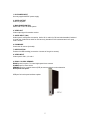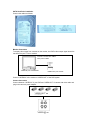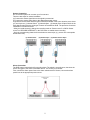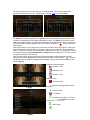
1
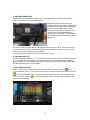
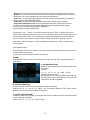
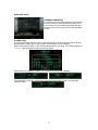
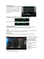
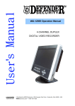
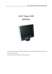
SEC-DVRMON20 4CH DVR MONITOR Short description guide of the DVR monitor. For full details of using the DVR monitor, refer to advanced manual. MANUAL ANLEITUNG MODE D’EMPLOI GEBRUIKSAANWIJZING MANUALE MANUAL DE USO HASZNÁLATI ÚTMUTATÓ KÄYTTÖOHJE BRUKSANVISNING NÁVOD K POUŽITÍ Description top panel: MENU/POWER: UP: DOWN: +: -: A) Long press: turn on or turn off the LCD monitor (Stand-by mode) B) Short press: used for menu of the monitor (not DVR) / move the cursor left or right. Select the parameters of the sub menu upwards. Select the parameters of the sub menu downwards Increase the volume or increase the value of the parameter in the sub menu. Reduce the volume or reduce the value of the parameter in the sub menu. Menu interface: When you need to adjust the parameters for the LCD monitor, you can short press “Menu/Power”. The menu will be display on the LCD screen. Then short Press “Menu/Power” to move the cursor leftwards or rightwards to select the option that user want to modify. Press “UP” of “Down” to move the cursor upwards or downwards. Then, press “+” or “-“ to increase value or reduce value. After finished the setting, press the “Menu/Power” several times to conform and exit. PICTURE: “BRIGHT”: 0~100. “CONTRAST”: 0~100. “COLOR”: 0~100. AUDIO: “VOLUME”: 0~100. FUNCTION: Press the button “UP” or “DOWN” to change the display mode “NORMAL & DOWN” of the LCD monitor. “ZOOM”: 16:9、4:3. SYSTEM: In this menu interface, users can choose the video format of display. “S-ROLOC”: AUTO、NTSC、SECAM & PAL. PRESET: In this menu interface, users can close the screen automatically in two ways. First, sets for the time of dormancy, the screen will be closed automatically in stipulated time. 2 “SLEEP”: 0~240 minutes. The value is increased or decreased by ten. The value of “sleep” indicates how long the LCD monitor will be turned off automatically if “OFF-TIME” is not set. Second, sets for closedown time and time of starting the LCD monitor, the screen closes and reveals at corresponding time point. “TIME”: --: --, the current time of system. “OFF-TIME”: --: --, the time of the screen turning off automatically. “ON-TIME”: --: --, the time of the screen turning on automatically. When modify “TIME、OFF-TIME、ON-TIME”, press “+” to adjust the value of minute and press "—“ to adjust the value of hour. Description front panel: 1 2 3 4 8 5 6 7 9 11 10 12 13 14 15 1. CH1 , CH2 , CH3 , CH4, QUAD Channel selection of QUAD display. Also cursor buttons for navigation through the DVR menu. 2. REWIND (REW) Rewind picture during playback. To stop rewind, press the REW button again. 3. PAUSE Pause picture during playback. To continue playback, push the PLAY button. 4. PLAY Playback of recordings Note: playback will start with the oldest unread video data and then continue playing. 5. FORWARD (FWD) Fast forward during playback. There are three levels of fast forward playback. 1) Play two times faster (x2) than the normal play. 2) Play three times faster (x3) than the normal play. 3) Play four times faster (x4) than the normal play. Note: to change the fast forward playback speed level, press the FORWARD button again. 6. STOP To stop playback. 3 7. RECORD (REC) To start manual recording. To stop recording, press REC button again. 8. HDD (Hard Disk Drive) LED (RED) System is recording or in playback mode. 9. POWER (PWR, GREEN) System power is ON. 10. IR EYE Receiver for remote control signal. 11. MENU/ESC (ESCAPE) Enter the menu. Escape for exit the menu. 12. UP To select a field in the menu, upwards 13. SELECT (SEL) / EDIT To change values in main menu or sub menu setting. 14. DOWN To select a field in the menu, downwards 15. PTZ (Pan, Tilt, Zoom) To enter PTZ control Note: The fast forward and rewind playback speeds will vary depending on the frame rate and record quality settings, as well as the number of channels recorded. Description back panel: 7 1 2 3 8 9 4 5 6 4 1. DC POWER INPUT Use only supplied AC/DC power supply. 2. AUDIO OUTPUT Audio for playback. 3. MAIN POWER SWITCH Switch ON or OFF the DVR system. 4. VIDEO OUT Video output signal for another monitor. 5. AUDIO INPUT (1&2) Audio input for microphone connection. Audio1 IN is audio for CH1 and also hearable if switched to quad view. Audio2 IN is audio for CH2 and only hearable if CH2 is selected and not if quad view is chosen. 6. PS2/MOUSE Connection for mouse (included). 7. HDD POSITION Position for HDD installing (remove the 4 screws of the grid to access). 8. VIDEO INPUT Video input for CH1, 2, 3 and 4. 9. RS485 / ALARM / SENSOR RS485 power line ports. To control high-speed dome camera. ALARM input for alarm device SENSOR input for 4 motion sensors (PIR) to start recording by motion detection Description side panel: USB port for back-up and software update 5 Description remote control: 1.CH1↑ Select CH1 or move cursor up 2.CH2↓ Select CH2 or move cursor down 3.CH3← Select CH3 or reduce value 4.CH4→ Select or increase value 5.QUAD 6.◄◄ (Z-) 7.► (F+) Quad view 8.►► (Z+) Forward or zoom+ or channel auto sequence 9. ● Manual recording or stop manual recording or 10. ▌▌ (F-) Pause or focus- 11. ■ 12. PTZ 13.Menu/ESC 14.Select/Enter 15.UP 16.DOWN Stop playing or stop dome running Rewind or zoom- Play record list or focus+ switch Level scan 6 PTZ switch Enter or exit setup menu Modify item or increase value Move up cursor Move down cursor GETTING STARTED Install a hard disk drive into your DVR. Connect cameras (up to 4) to DVR. Connect other peripheral devices (mouse, external motion sensors or alarm) if necessary. And PS/2 Mouse must be connected to DVR before startup system. Plug the power cord into the power jack on the wall. Start TV Monitoring and Recording. Make sure that a hard disk drive and camera(s) are properly installed. The hard disk (IDE) jumper setting must be set to “master” jumper setting. If the power is turned off while recording (i.e. a power failure), the DVR will enter “Power Recovery” modes at start up, detect that it has been shut down, and then reinitiate the recording process. HARDWARE SETUP IDE Hard Disk Drive Installation (A) Make sure that HDD Jumper setting as “Master” Before installing hard drive, set jumper as “Master”. The master jumper setting varies depending on the hard drive manufactures. Refer to manufacture’s manual for master jumper setting. For example, the model of HDD is Seagate. (B) Connect the ribbon cable (IDE) cable & power cable Back side of hard disk 7 SATA Hard Drive Installation Connect the cables as follows. Monitor Connection To display video image from cameras on the monitor, the DVR’s video output signal should be transferred to your TV set or monitor. Connect a monitor with “VIDEO OUT” ports on DVR “VIDEO IN” port on MONITOR “VIDEO OUT” port on DVR Connect “VIDEO IN” of the monitor to “VIDEO OUT” of the DVR system. Camera Connection Connect between “VIDEO IN” of your DVR and “VIDEO OUT” of camera with video cable and plug in the camera’s power adapter. “VIDEO OUT” on CAMERA “VIDEO IN” 8 on Sensor Connection Our 4 CH DVR system can connect up to four sensors. There are two steps for sensor installation. (a) Connect the sensor signal lines to the signal input terminal. (b) Connect the sensor power lines to the appropriate power source. In general, there are three different types of sensors available in the home electrics store, where you can buy them. (1) Normal-Close. (2) Normal-Open. (3) Normal-Close & Open. Below is the brief diagram about how the each type of sensor is installed into DVR. The procedure for sensor install action is as shown below. * After you install sensor(s), change the recording mode as “Sensor record” or “MD & Sensor record” on “RECORD SCHEDULE” in the DVR menu to enable sensor recording. * Only the corresponding channel will record when a sensor trips, (e.g. sensor one corresponds with channel one). (1) Normal-Close (2) Normal-Open (3) Normal Close & Open Alarm Connection The DVR has an internal switch for sounding alarm. The switch is normally open, but when the sensor is triggered, the alarm is activated as well. The circuitry is as follows. First, connect the alarm power lines to the alarm switch terminal. Second, connect the alarm power lines to the appropriate power source. DVR Rear Panel ALARM 9 Mouse Connection Connect PS/2 mouse with the port below on the system. And PS/2 Mouse must be connected to DVR before startup system. DVR Power Connection Connect a DVR power adapter to the adapter jack at the rear panel of DVR unit. And turn the power switch on. It will boot up the system. If users install a new hard disk drive, it will ask for HDD formatting before a system starts to run (Below Fig). Choose format option pressing “PLAY” button. Below is the information of input/output voltage for the power adapter. Input: AC 100-240V, 50/60Hz, 1.5A Output: DC +12V == 5A 5. SETUP After installing a new hard drive on the system, user had better to format the hard disk drive first. If the system includes login window, and there will be three password levels in the system, including admin (highest), operator, and guest (lowest). If the user does not login the system, he can only view live video display. 10 The system allows up to four user accounts. The administrator can set up the login name, password and level for each user. (Please refer to Section 5.6.2 for Account Setup.) The admin can operate everything. The operator can operate anything except examining user accounts, formatting HDD and modifying his password level. The guest can operate live video display and image playback, or modify some parameter value that is independent of recording. If user has no right to modify parameter value, there will be an identifier “ ” on top right corner of the screen. After system boot-up, hold a right mouse click button and there will be login window. Hold a left mouse click button to click the order of “Account”, and input correct account. Then left click the order of “Password” and input correct password. At last left click “Login” to enter system. There is one factory-preset login “account/password” “admin/111111” at admin level. The user can use it to login the system for the first time. After login the system, hold a right mouse click button and there will be suggestive window options on the monitor (Fig (a)). Hold a left mouse click button to click the icon “ ”. Or press the MENU button to make any changes of DVR settings. You will see the screen below on the monitor (Fig (b)). Suggestive window options: Channel 1 view Channel 2 view Channel 3 view Channel 4 view All channel view ● Manual recording or Stop manual recording Fig (a) ► Play record list PTZ Switch Channel auto sequence. The icon “ ” won’t display if the order of “auto sequence” is “OFF”. Menu option Fig (b) 11 Logout The DVR Front Panel or Remote Control Press the “UP” or “DOWN” key on the DVR front panel or remote control to move the cursor. Press “SELECT” button on the front panel or remote control in order to change the settings. In the MAIN MENU, the cursor “ ” will be shown on the screen right next to each sub menu. To previous, press “MENU” button on the front panel or remote control. The Mouse Control Move the mouse up or down to move the cursor. Hold a left mouse click button to change the settings. Click a right mouse to previous. CAMERA Use this option for video color adjustment for each channel (1,2,3,4). Go to DISPLAY option to enable or disable for screen display of each camera. Modify camera name of each channel that user wants to. RECORD Use this option to choose the channel (1,2,3,4) for recording. Only selected channel will be recorded no matter how many camera channels are displayed on the screen. 12 A: [RECORD FRAMERATE] Change the record frame rate for each channel. The higher the record frame rate, the more natural movement you will see while playback. Independent each channel frame rate adjustment is possible. System default value is 12 frames per second with each channel, which means the system will record 48 frames per second with all channels. User can set frame rate as 3~25 frames per second with each channel. The max value of total frames per second with all channels is 50 frames. Press button [SEL]/ [CH4] or hold the left mouse button to click icon “► to increase the record frame rate for each channel. Press button [CH3] or hold a left mouse button to click icon “◄ to decrease the record frame rate for each channel. If you make the record frame rate off, the channel won’t record. B: [RECORD QUALITY] Choose record quality among 1 / 2 / 3. The best record quality is 3, and the lowest record quality is 1. The higher the record quality is, the higher the video image quality is well you playback. Higher quality cost more hard disk space. Record frame rate, record quality and hard disk space will affect total record time of DVR system. C: [RECORD SCHEDULE] Notice: To start motion record, make sure the period that you intend to record is “ ” in the “record schedule” menu. To start sensor record, make sure the period that you intend to record is “ ” in the “record schedule” menu. And to start motion & sensor record, make sure the period that you intend to record is “ ” in the “record schedule” menu. The time period 00:00:00 is the same period as 24:00:00. 13 - Grey bar: No record will be made for this time period if user can’t activate manual recording. - Red bar: The time period with a red bar will activate continuous recording mode (Time record) unless there is any manual stopping during recording during that time. - Green bar: The time period with a green bar for built-in motion recording (MD). (See also the following chapter “MOTION DETECTION”) - Yellow bar: The time period with yellow bar will activate external sensor recording. - Half-yellow and half-green bar: The time period with half-yellow and half-green bar will activate the combination of built-in motion (MD) recording and external sensor (Sensor) recording. (See also the following chapter “SENSOR”) [Using keypad or remote control button] Press button「Up」/「Down」to move the prompt, then press「SEL」to adjust video record method during each time period every day. User can adjust the same record method during some time periods synchronously, move the prompt first and press [QUAD] button on the DVR front panel or remote control, then move the prompt to enlarge area(CH1 for upwards、CH2 for downwards、CH3 for leftwards、CH4 for rightwards), and then press「SEL」to adjust video record method. [Using Mouse button] While holding a left mouse click button, move the mouse to enlarge area and then single left click to adjust video record method. To previous, to save the parameters that user sets up. ALARM Using SELECT button or hold a left mouse button to click icon “◄ / ►, adjust parameters of each option. A: [ALARM DURATION] It sets the alarm duration time (in seconds) after alarm is activated. Value at “05、10、15、20、25、30、CONT、OFF”(in seconds). Default at “OFF”. By changing the value in the ALARM DURATION, you can adjust how long the alarm will last in seconds. The alarm device should be installed. B: [BUZZER DURATION] It sets the buzzer duration time (in seconds) after alarm is activated. Value at “05、10、15、20、25、30、CONT、OFF”(in seconds). Default at “OFF”. When “buzzer duration” is “cont”, the buzzer will work continuously. C: [EVENT REC DURATION] It sets the record time of duration (in seconds) after sensor recording or motion recording or MD & sensor recording is activated. Value at “05、10、15、20、25、30”(in second). 14 D: [SENSOR] Activate / deactivate or choose the type of sensor. There are three different modes for sensor setting: N.C (NORMAL-CLOSE) & N.O (NORMAL-OPEN) & NONE. Select “None” to deactivate sensor recording or if there was no sensor installed in DVR system. Chose the type of sensor (N.O or N.C) installed in DVR. E: [MOTION DETECTION] [CHANNEL] Select the channel (1,2,3,4) for recording mode by internal motion. [SENSITIVITY] It adjusts the sensitivity of the built-in motion sensor on the DVR system while recording. The higher the number, the lower the sensitivity is. Value at “1、2、3、4、Off”. The maximum sensitivity level is 1. [MOTION AREA] Use this option to select the range of motion detection area. Use the keypad button, remote control button, or mouse click to assign the area. The keypad and mouse control instructions are below. [Using keypad or remote control button] Press [SEL] once to pitch on the area, press [SEL] twice to cancel the area. CH1 - Up / CH2 - Down / CH3 - Left / CH4 - Right [Using Mouse button] While holding a left mouse click button, move the mouse to select, deselect, or reselect the motion detection area for recording. By the way, the area only can be selected from up to down and from left to right. When the block is covered by blue shadow, it’s active to record. When the block is transparent, it can’t be recorded. After completed the motion area setting, press “MENU” button or hold a right mouse click button to exit. To start Motion Record, user must complete the “Motion area” setup. SCREEN [BORDER] User can make the white borderline around each channel to appear or disappear by using this option to be “on” or “off”. [AUTO SEQUENCE] This is for auto screen switch rotation. Value at “Off、1~10(in seconds)”. Default at “Off”. [VIDEO ADJUSTMENT] You can move the entire video screen up, down, left, and right using this option. Keypad assignment in the front panel or remote control is below: -CH1 for up, CH2 for down, CH3 for left, CH4 for 15 right. Mouse function: Hold a right mouse click button, there will be some icons on the screen as follows “ ”. Hold a left mouse click button to click each icon to select. -“▲for up, ▼ for down, ◄ for left, ► for right, “ ” for ESC. AUDIO Make the record “ON” to enable sound recording when a microphone device is attached in AUDIO INPUT port on the system. Adjust volume for speaker and the intensity level of sound recording. To make the sound enabled for speaker, leave the mute “OFF”. SYSTEM Fig (c) Fig (d) In this menu, you can see the information of the hard disk drive installed on the system, change the system password, adjust keypad tone, browser event list or adjust current time on the system. If user login the system at admin level, the menu bar will be displayed as Fig (c). The user can enter into the order of “Account” to examine all user accounts, add or delete user that he wants to (Please refer to section 5.6.2 for account setup). If user login the system at operator or guest level, the menu bar will be displayed as Fig (d). The user can only modify its own password. (Please refer to 5.6.3 for password setup) 16 HARD DISK SETUP [OVERWRITE ENABLED] If you choose Yes, recording continues and overwrites previous recording when hard disk drive space is full. If you choose No, the recording stops when the hard disk drive is full. It won’t record until “overwrite enable” is “Yes”. [FORMAT HDD] If you format the hard disk drive, all the video data stored on the hard disk drive will be deleted. Remind that the system has no restore option once the hard drive is formatted. When you choose this option, it will ask for password before formatting. The default password is “111111”. Type the password and press any key button. When HDD is successfully formatted, you will see the message below blinking. If the password is incorrect, you will see the below message blinking. Then try to type right password again. 17 ACCOUNT SETUP Only user log in the system at Admin level, the Account Setup allows the administrator to add new users, delete existing ones, and modify the user’s name/password/level. The system allows up to 4 user accounts. [Account]/[Password] In setup Menu display, move the cursor to change the highlighted option to Account, and then press [SEL] to call up Account/Password as shown. All numbers, letters and sign in the pane can be used as user account or password. Press 「SEL」to input value, and move the prompt to the option of “ENTER”, press 「SEL」to confirm. — CH1 for up, CH2 for down, CH3 for left, CH4 for right, Press “Shift” for change characters. [Level] Move the cursor to change the highlighted option to Level, and then press [SEL] to adjust user level (operator/guest). 18 PASSWORD SETUP The default password is 111111. All numbers, letters and sign in the pane can be used as password. Press 「SEL」to input value, and move the prompt to the option of “Enter”, press 「SEL」to input current password. — CH1 for up, CH2 for down, CH3 for left, CH4 for right. And the same operation measure to input new password and confirm password. When password change succeed, user will see the below message blowing. When password change fail, user will see the below message blowing. CLEAR ACCOUNT INFO If you choose ON, the account information will be cleared when you logout the system. If you choose OFF, the account information will be kept when you logout the system. Logout “Logout” can be set as “1~10(in minutes)、Off”. It decides how much time the system will logout automatically if user can’t operate the system beyond the period. KEYPAD TONE Make the keypad tone “ON” or “OFF” to enable or disable keypad tone during operating. TIME SET You can adjust the current time, date and year at any time. Set the current time so that the video back-up data can be played without time shifting later on. There are three types of date, as follows: *** YYYY/MM/DD (2009/06/13 - year/month/day). *** MM/DD/YYYY (06/13/2009 - month/day/year). *** DD/MM/YYYY (13/06/2009 - day/month/year). Time format is as below. *** 01:00:00 - hour: minute: second 19 To move the cursor on the screen, use “UP” and “DOWN” key on the DVR front panel or remote control and then press “SELECT” button to change the numeric value. Once you finish time setting, press “MENU” button. Then press “DOWN” key and “SELECT” button to apply the new time set. Or move the mouse to move the cursor up and down, hold a left mouse click button to change the numeric value. Once you finish time setting, hold a right mouse click button to return. Then move the mouse to the order of “Apply” to left click to apply the new time set. EVENT LIST EVENT LIST function enables playback by event. On the Event List menu, it shows all past recorded video, start time and end time of each recorded video, and etc showing recording year/date/time in list. The HDD can be stored 300 pieces of event in it at most. If the events are over 300 pieces, user can play previous event according to input time period if the data hasn’t been overwritten. To playback by EVEN LIST, using [UP]/[DOWN] or channel number (CH3 for Page Up or CH4 for Page Down) key on the front panel or remote control, select the event that you want to playback and press “PLAY” button. Another way, move the mouse up and down or click the left mouse button (“◄ for Page Up or ► for Page Down), select the event that you want to playback and double click the left mouse button. Then it wills playback the recording video data. PTZ SETUP Adjust the RS485 setting depending on the PTZ camera that you have. Our DVR system supports PELCO-D protocol and PELCO-P protocol. Then we can see the diagram that is on the left. For example, we select the channel 1 to set up. Dome’s address is 1. Protocol makes use of PELCO-D. Baud rate is 2400 and Dome’s speed is 7. CHANEL: Select a camera channel where PTZ camera is connected. ADDRESS: Dome’s address “0-255” (PELCO-D) and “0-31” (PELCO-P). PROTOCOL: Including “PELCO-D”, “PELCO-P”. Set the protocol according to the dome’s protocol. BAUD RATE: Press “SEL” button to select the value 1200, 2400, 4800, 9600, 19200bps. SPEED: Having “1-10” to select. PRESET: If protocol is PELCO-D, preset includes “1-32”. If protocol is PELCO-P, preset includes “1-255”. When it displays 0, it suggests that the place’s preset is not using. 20 Button function On the Front Panel or Remote Control: 「Select」:Make sure the setting. 「Up」「Down」:Move the cursor. 「REC」: Auto scan. 「Ch1」「Ch2」: Move the dome upwards and downwards. 「Ch3」: Move the dome leftwards or Reduce Value 「Ch4」: Move the dome rightwards or Increase Value. 「STOP」:Stop the dome running. 「REW」「FWD」:Zoom. 「Pause」「Play」: Focus. Mouse function: Left Mouse: Click the icon “► or ◄ to adjust value. Right Mouse: Previous. Preset setup: User must set preset at first. The address, protocol and baud rate of DVR is consistent with Dome’s. You can make use of buttons to control dome and save the preset. If user wants to call preset, user can modify the value of preset to come true. Press「Select」button to finish the order of “call preset”. User can perform auto scan when he saves the presets within cruise locus. Then he needs to press 「Select」button to finish the order of “auto scan”, the dome will run all along unless user presses「STOP」button to stop it. PTZ Mode: Enter into PTZ mode and hold a left mouse click button, there will be a piece of message on the screen (Right FIG). Icon function: “▲▼►◄: Move the dome upwards、downwards、leftwards and rightwards. “■: Stop the dome running. “ 、 ”: Focus. “ 、 ”: Zoom. “ ”: Auto scan. “ ”: Previous. 21 Attention: User can start-up automatic scout in “PTZ SETUP” menu or PTZ mode. It doesn’t stop when user exits. If user wants to stop scouting, press 「STOP」button in PTZ mode. During live view, user can press「PTZ」button to enter PTZ mode, and then user can operate to control the dome according to the method of above paragraphs. F/W UPGRADE This menu is for firmware upgrade of DVR system through USB host (USB memory stick) connection, you can simply upgrade the system once you connect the USB memory stick that contains a firmware file. [CAUTION]: 1. Do not turn off the system while the system is upgrading. Otherwise, it will cause the breakdown of the system that needs a special recovery process. 2. If you don’t install a HDD in the DVR, the system can’t be upgrade. 3. Before the system is upgrade, you must stop recording. LANGUAGE Our system supports multi-language OSD. As a whole it includes two types of language system (western and east). The language is provided with user’s requirement. In western language user can choose either English、Italian、Polish、Spanish 、France、Greece、German、Dutch 、Portuguese or Turkish for display on the screen. In east language user can choose either Chinese、English、Japanese、Russian or Bulgarian for display on the screen. On the menu of “Language”, you can move the cursor to change it by pushing “SELECT” button on the front panel or remote control, and also can move the mouse to single left-click to select the language. Western Language (optional) Eastern Language (optional) EXIT After you change setting on DVR menu, you need to confirm the changes under EXIT menu. [EXIT & SAVE CHANGE] Save change and go back to main screen. [EXIT & DISCARD CHANGES] No change and go back to main screen. [LOAD SETUP DEFAULT] Load default setting. 22 PLAYBACK WITH TIME SEARCH FUNCTION This is an enhanced playback option, which enables the user manually to adjust a specific starting time for playback. [Keypad Control]: In order to playback with time search function, press "PLAY” button on front panel or remote control first. And then press “SELECT” key to change the value of the playback start date & time and press “PLAY” button again. The playback will start from the date & time indicated by the user. [Mouse Control]: Hold a right mouse click button and left click the icon “►. And then press the left mouse button to change the value of the playback start date & time and press the right mouse button. Then hold a left mouse button to click “Search”, the playback will start from the date & time indicated by the user. BACKUP via USB memory stick Our 4-channel DVR system has an enhanced back-up feature so that it’s possible to transfer the video data image recorded on the hard drive to USB memory stick drive. Before you back up a stream of video data, have the USB memory stick to be ready and attaché them into DVR system. In order to save the video data with these back-up devices, you should first start with playback. And then press “MENU” button. Use “UP” key or “DOWN” key move the prompt, then press “SELECT” button to set start time and the end time of the recorded video data, which will be saved on back-up devices. If you want to setup the end time faster, you can press the button [►►FWD] to change the play speed that you want, and then press [DOWN] to select end time again. After setting the time of backup, move the prompt to the option “USB copy”, then press “SELECT” button to backup the video data on USB stick. After playback, press “MENU” button. Then using “UP” and “DOWN” key to set the time period of recorded video data that you want to save on the back-up devices. USB copy: Move the prompt to “USB copy”, and press “SELECT” button or hold a left mouse click button to back up a stream of video data on USB memory stick. 23 It will take a few minutes to write the video data on USB memory stick. The file size number is going up until it’s done with the message below. WRITING… Then it will show the following message on the screen. FIXATING… Take out the USB memory stick and attach it into your PC when it’s done. Press “PLAY” button to continue with a system. To view the video image saved on back-up devices on the computer, you need our software provided with this package. RECORDING LENGTH Video System is “PAL”. Estimate record time basing on 320G Byte HDD. The highest record quality is 3 and the lowest record quality is 1. Record Speed 50F/Sec 25F/Sec REC Quality DATA RATE (GB/Hour) Record Time (Hour) 3 4.4 73 2 2.8 114 1 2.3 139 3 2.4 133 2 1.6 200 1 1.3 246 24 PLAYBACK WITH BACK-UP VIDEO DATA ON PC Install 1). Put the Driver Program CD in your CD-ROM. 2). Go for installing by setup. 3). Set up the install directory. 4). Execute: Start >Program >VxViewer >Vx4SLPlayer. Program Interface Double click icon “ ” on desktop to run the program. 25 Button Function 1. Open File 2. Fast Backward 3. Play Reverse 4. Previous Frame 5. Pause 6. Next Frame 7. Play 8. Fast forward 9. Still Capture 10. Split 1 11. Split 4 12. Volume Scroll Bar 13. Mute On/Off 14. Playing Scroll Bar 15. Minimize the window 16. Close the window 1) Click “ ” to play the video recorder in “*.VVF” format. 26 2) Still Capture Click “ ” to still capture. Click the right mouse button to select “Options…” to setup path for still capture. Click the left mouse button to select folder that you want to, for example select the folder as “E:\VOC 4CH\backup”. 3) In “Options” window, you can setup other menu selection such as “General & On screen display date/time format”. Always on top (A): The client window will always display on top of all the windows. Use DirectDraw: If your PC’s graphic card supports DirectDraw, images can be displayed via the method DirectDraw on your PC’s graphic card. Show playback time (T): The playback time will display on screen during play backing. On the menu selection “On screen display date/time format”, you can adjust the date/time format displayed on screen that you want to. 4) Press the keyboard “F1” or click the right mouse button to select option “About Viewer F1”, you can see the version of current client. 27 5) Translate “VVF File Format (*.VVF)” into “AVI File Format (*.AVI)”. According to the below figures, first click the right mouse button to select the option “Export”, and then click the left mouse button you will see the window “Export To AVI”. Secondly select channels you want to export, you can choose the audio to export whether or not. Thirdly click “ ” to select input file and output file, and click “ ” to select video compression mode. Finally click “ ” to start, and progress will be showed at percentage. Note: 1、When selecting video compression mode, user had better to test the compression that he selects is matching with his computer whether or not. Or else the transposition AVI file will be failed possibly. 2 1 Audio: The audio will be backup if the video data include audio. 2)Audio: The audio won’t be backup. 6) Capture If you want to save moiety of VVF file format (*.VVF) on your computer rapidly, you must make sure the playback view be in pause state. Drag playing scroll bar to select start time, click the right mouse button to select the option “Capture”, then left click “Mark In”. Drag playing scroll bar ahead to select end time, click the right mouse button to select the option “Capture”, then left click “Mark Out”. Last left click “Export” and there will be a window “Capture” on screen. The “Output Size” is the size of output file. Left click “ ” to setup save path. Then left click “ ”. 28 7) Open Disk… User can playback the record data in the HDD directly through the client software. User can install the HDD to PC directly. Click the option “Open Disk…”, and there will be a dialog of “Disk Select”. Select the HDD including video data to play. 29 SPECIFICATION ITEM DESCRIPTION Video Format NTSC / PAL Operation System Linux Camera Input Channel 4 channel Composite BNC Video Output Channel 1 channel Composite BNC NTSC Recording Frame Rate PAL Record Mode Display Resolution Recording Max 60 fps (Total) Max. 30 frames/s (Each Channel) Max.50 fps (Total) Max. 25 frames/s (Each Channel) Time schedule, Motion detection, Sensor activated, Motion detection & Sensor activated NTSC:720 x 480 PAL:720 x 576 NTSC: 640×224 PAL: 640×272 Compression Method HDD Support Sensor, Alarm Video Quality: Low@13K Bytes; Enhanced MJPEG Normal@ 16K Bytes; High@20K Bytes. Over SATA or IDE ATA –100 Interface 1.0TBytes HDD×1 4 Input (Normal Open / Normal Close) 1 Output (Alarm) (12 Pin DIP Switch) Camera Signal Loss Alarm 2 Pin for RS485 control Pan/Tilt/Zoom PTZ、RS485、 YES PELCO-D、PELCO-P Audio Input 2 Channel Composite RCA Audio Output 1 Channel Composite RCA USB YES OSD For media Backup and software upgrade Support multi-language 38KHZ Remote Control Unit Optional PS/2 Mouse Optional Power Input 100-240VAC/DC 12V , 5A(Adapter supplying) Length 300mm * Width 290mm * Height 70mm Dimension 30 APPENDIX System Connect Sketch Map Fitting Come Along With DVR 1. Power Adapter 1pcs 2. Power Cord 1pcs 3. Remote Control (Optional) 1pcs 4. User Manual 1pcs 5. USB Drive CD 1pcs 6. Mouse (Optional) 1pcs 7. Batteries of Remote Control 1pcs 31 Used the compatible USB Stick. In case the noise occurs on USB line due to a variety of reasons such as power noise, it might cause the error while data transferring process. In this case, it requires re-transfer the date on memory stick. If the device can process things normally for this kind of exceptional case, things are okay. However, for some case, it doesn’t operate normally. For example, in case of PC, it might not cause any problem under this kind of situation because it is immune to process this kind of exceptional cases. However, in case of our products, they work only with the limited resources, which end up with restore-impossible situation. WORKING DEVICE LIST MAKER SONY SAMSUNG TRANSCEND APACER SANDISK FLEX KINGSTON KINGSTON LEMON MODEL MICROVAULT (SOK-USM1GJ) SUM-LCB1 JF V30 Weblink (SYE5003358) CRUZER micro FD-02 Data Traveler Data Traveler LEMON USB Drive 32 SIZE 1GB 1GB 2GB 2GB 4GB 1GB 2GB 1GB 1GB Safety precautions: Do not expose the product to water or moisture. Maintenance: Clean only with a dry cloth. Do not use cleaning solvents or abrasives. Warranty: No guarantee or liability can be accepted for any changes and modifications of the product or damage caused due to incorrect use of this product. General: Designs and specifications are subject to change without notice. All logos brands and product names are trademarks or registered trademarks of their respective holders and are hereby recognized as such. Keep this manual and packaging for future reference. Attention: This product is marked with this symbol. It means that used electrical and electronic products should not be mixed with general household waste. There is a separate collections system for these products. 33 Declaration of conformity / Konformitätserklärung / Déclaration de conformité / Conformiteitsverklaring / Dichiarazione di conformità / Declaración de conformidad Megfelelőségi nyilatkozat / Yhdenmukaisuusvakuutus / Överensstämmelseförklaring / Prohláení o shodě / Declaraţie de conformitate / Δήλωση συμφωνίας ______________________________________________________________________________________ We, / Wir, / Nous, / Wij, / Questa società, / La empresa infrascrita, / Mi, / Me, / Vi, / Společnost, / Noi, / Εμείς, Nedis B.V., De Tweeling 28, 5215MC, ’s-Hertogenbosch The Netherlands / Niederlande / Pays Bas / Nederland / Paesi Bassi / Países Bajos / Hollandia / Alankomaat / Holland / Nizozemí / Olanda / Ολλανδία Tel. / Tél / Puh / Τηλ. : 0031 73 5991055 Email / Couriel / Sähköposti / e-post: [email protected] Declare that product: / erklären, dass das Produkt: / Déclarons que le produit: / verklaren dat het product: / Dichiara che il prodotto: / Declara que el producto: / Kijelentjük, hogy a termék, amelynek: / Vakuutamme, että: / Intygar att produkten: / prohlauje, e výrobek: / Declarăm că acest produs: / Δηλώνουμε ότι το προϊόν: Brand: / Marke: / Marque: / Merknaam: / Marca: / Márkája: / Merkki: / Märke: / Značka: / Μάρκα: König Electronic Model: / Modell: / Modèle: / Modello: / Modelo: / Típusa: / Malli: / Μοντέλο: SEC-DVRMON20 Description: / Beschreibung: / Description: / Omschrijving: / Descrizione: / Descripción: / Megnevezése: / Kuvaus: / Beskrivning: / Popis: / Descriere: / Περιγραφή: EN: 10" MONITOR WITH INTEGRATED 4 CHANNEL HARDDISK RECORDER Is in conformity with the following standards: / den folgenden Standards entspricht: / est conforme aux normes suivantes: / in overeenstemming met de volgende normen is: / è conforme ai seguenti standard: / es conforme a las siguientes normas: / Megfelel az alábbi szabványoknak: / Täyttää seuraavat standardit: / Överensstämmer med följande standarder: / splňuje následující normy: / Este în conformitate cu următoarele standarde: / Συμμορφώνεται με τις ακόλουθες προδιαγραφές: EN 55022:2006 (Class B), EN 61000-3-2:2006, EN 61000-3-3:1995/A1:2001/A2:2005, EN 55024:1998/A1:2001/A2:2003, IEC 60065:2001, EN 60065:2002;A1:2006 EU Directive(s) / EG-Richtlinie(n) / Directive(s) EU / EU richtlijn(en) / Direttiva(e) EU / Directiva(s) UE / EU direktívák / EU Toimintaohje(et) / Eu Direktiv(en) / Směrnice EU / Directiva(e) UE: / Οδηγία(ες) της ΕΕ 2004/108/EC, 2006/95/EC ‘s-Hertogenbosch, 23-12-2009 Mrs. / Mme. / Mevr. / Sig.ra / D. / Fru / Paní / Κα : J. Gilad Purchase Director / Einkaufsleiterin / Directrice des Achats / Directeur inkoop / Direttore agli acquisti / Director de compras / értékesítési igazgató / Ostojohtaja / Inköpsansvarig / Obchodní ředitelka / Director achiziţii / Διευθυντής αγορών Copyright © 34