1
US 20110313334A1
(19) United States
(12) Patent Application Publication (10) Pub. No.: US 2011/0313334 A1
(43) Pub. Date:
Almeida et al.
(54)
BODY THERAPY DEVICE
(76) Inventors:
(21) App1.No.:
13/161,119
(22) Filed:
Jun. 15, 2011
Related US. Application Data
(60)
Publication Classi?cation
(51)
Int. Cl.
A61H 7/00
(52)
us. c1. ...................................................... .. 601/134
Robert S.Almeida, Boston, MA
(US); Douglas E. Stern,
Providence, RI (U S)
Provisional application No. 61/355,375, ?led on Jun.
16, 2010.
Dec. 22, 2011
(57)
(2006.01)
ABSTRACT
The body therapy device includes a thoracic pad having a top
edge and a rear surface With a base having a bottom edge, a
front angled surfaced and a rear surface. A spherical member
is attached to the angled front surface of the base and includes
a hard inner core therein. A pump, With active and passive
elements, is provided to enable the user to adjust the hardness
of ball portion of the device for customized therapy to a head
and neck region. As a result, the device of the present inven
tion is effective for physical therapy and treatment of a Wide
range of ailments and conditions.
Patent Application Publication
Dec. 22, 2011 Sheet 1 0f 9
US 2011/0313334 A1
Patent Application Publication
Dec. 22, 2011 Sheet 2 0f 9
US 2011/0313334 A1
Patent Application Publication
Dec. 22, 2011 Sheet 3 0f 9
US 2011/0313334 A1
Patent Application Publication
Dec. 22, 2011 Sheet 4 0f 9
US 2011/0313334 A1
Patent Application Publication
Dec. 22, 2011 Sheet 5 0f 9
FE. 5a
US 2011/0313334 A1
Patent Application Publication
Fig. 6b
Dec. 22, 2011 Sheet 6 0f 9
US 2011/0313334 A1
Patent Application Publication
Dec. 22, 2011 Sheet 7 0f 9
US 2011/0313334 A1
Patent Application Publication
4{K1i%t.5:
Dec. 22, 2011 Sheet 8 0f 9
US 2011/0313334 A1
Patent Application Publication
. .Z
Dec. 22, 2011 Sheet 9 0f 9
US 2011/0313334 A1
US 2011/0313334 A1
BODY THERAPY DEVICE
CROSS REFERENCE TO RELATED
APPLICATION
[0001] This application is related to and claims priority
from earlier ?led provisional patent application Ser. No.
61/355,375, ?led Jun. 16, 2010, the entire contents thereofis
incorporated herein by reference.
Dec. 22, 2011
pains and symptoms along With loWer back pain and other
symptoms, dysfunction, and disease.
[0005] Further, more serious pathology eventually occurs,
such as vertebral subluxations, facet joint arthrosis, spine
sprains and strains, disc herniations and extrusions, disc des
sication, cervical spine spondylosis, other discs pathology
and spine spondylosis, and facet and central cord stenosis,
among other conditions. If left untreated FHP can cause lung
and vascular disease. Due to decreased function, lung capac
ity can be decreased 30%, shorter breaths are taken due to
BACKGROUND OF THE INVENTION
bio-mechanical decreases, and thus, capacity of vital lung
[0002] The invention relates generally to devices and meth
ods to help alleviate neck pain, upper back pain, shoulder
pain, headaches, cervical spine sprain and strains such as a
function decreases. FHP has been found in a recent study to
cause a 1.44 greater chance of mortality. FHP is currently an
epidemic in our population due to the performance of our
daily and Work activities. It is expected to Worsen as sug
gested in the evidence base and current research. Causes of
cervical spine hyper ?exion hyper extension injury or Whip
lash trauma, and symptoms associated With poor posture,
forWard head position (FHP), aid in concussion prevention,
decrease post concussion syndrome, pain and symptoms
from temporal mandible joint dysfunction and cervical spine
and spine pathology and general spine pain and muscle ten
sion. Further some attributes of this device Will include, but
are not limited to: Decreased pain, decreased muscle spasm
and tension, increased cervical spine range of motion, stabi
these aforementioned conditions include many looking doWn
positions if not all forWard cervical spine ?exed positions, and
repetitive positioning of the head and neck such as; cell phone
and smart phone use, texting, driving a vehicle, sitting posi
tions, video game playing, computer use, reading, Writing,
academic school Work type activity, and some sleeping posi
tions.
liZe and strengthen cervical spine muscles, ligaments, and
[0006] Further, eating positions and motions, many sports
tendons among other joint and connective tissues in the cer
activities, many exercise positions, and any other body posi
vical spine and other spine regions and body areas and
increase in neurological and neurophysiologic function.
[0003] In the medical ?eld, nociceptive and neuropathic
neck pain, upper back pain, spine pain in a radicular, sclero
togenous, myofacial or dermatomal pattern or general spine
tion that causes body strain and tension. It is Well knoW that
pain, shoulder pain, headaches, pain from TM] dysfunction,
pain and symptoms associated With poor posture, forWard
concussions are caused by head trauma, striking the head, and
a rapid increase or decrease of head motion, most commonly
in a ?exion-extension motion and in rotational motions such
as an acceleration or deceleration of the head suddenly, cre
ating a force (delta-v) to be received above tolerance to the
individual.
head position (FHP), post concussion syndrome symptoms,
[0007]
symptoms from concussion and cervical spine and spine
devices and methods to help With some of the mentioned
pathology, are Well knoWn. These above mentioned injuries,
above tasks including strengthening the muscles of the spine
and body in general. Further, there have been devices and
conditions, postures and syndromes frequently result in the
undesirable functional decreases of the cervical spine region,
other aforementioned regional dysfunctions and cervical
There have been attempts in the prior art to provide
methods that assist to attempt in improving posture of the
spine and body in general.
extensor muscle dysfunction and an imbalance of the ?exor
[0008]
and extensor muscle ratio of the cervical spine along With
aberrant changes in other structures and function including
motion to the above-mentioned regions and decrease of the
ers that can be rolled against some parts and portions of the
body that are experiencing pain. This is not adequate to reach
all parts of the anatomy of the body and is dif?cult for the
neurological and neurophysiologic function in these regions.
patient to use on himself or herself. It is less or not at all
The overall dysfunction of the cervical and thoracic spine
joints, muscles, and other connective tissues along With
effective on the cervical spine. It further does not deliver
decreased neurophysiologic function contributes to and are
dence base the most effective method), to correct the above
conditions and restore function. This method also does not
provide the above-mentioned needed elements to correct the
causally related to anterior head gravitation, Which is also
knoWn as, forWard head position (FHP). Speci?cally, doWn
Ward facing positions and postures cause concurrent hypo
For example, prior art devices include padded roll
active treatment or isotonic therapeutic exercise, (in the evi
aforementioned stated problems that this device patent does
tonic (lengthening) and hypertonic (shortening) of muscles,
ligaments, and tendons, in the said regions, degeneration of
cervical spine vertebral facet joints (Zygapophysial joints),
loss of cervical spine disc height, (disc dessication) and irri
tion (physiology), must also be restored. Function needs to be
tation to cervical spine nerves.
reinitiated most effectively by an active isokinetic modality
[0004] The foregoing leads to an anatomical hypolordosis
of the cervical spine that, in turn, leads to aberrant cervical
spine facet joint movement. Further an anterior forWard posi
tion of the shoulder in relationship to the body in the coronal
such as this device patent. It is Well knoW in the literature, that
passive attempts are not effective.
promote. It appears not to restore function or create improved
posture or structure (anatomy). It is Well knoW in the medical
community that to restore posture and form (anatomy), func
[0009] Also custom tables, With padding thereon, have
been provided on Which the patients can lay to help relieve the
or frontal plane occurs, an increased kyphosis of the thoracic
tension associated With the some of the above activities. This
spine further occurs, and other postural de?cits such as pelvic
tilting, and a decrease lumbar lordosis predictably folloW.
These bio-mechanical instabilities among others, and poor
posture lead to neck pain, upper back pain, headaches, tem
poral mandible joint pain, shoulder and arm pain, radicular
type of passive treatment is further not effective for postural
restoration and functional correction. Further, massages by
another person are helpful as Well as some other professional
health provider methods. These are very expensive and can
not be carried out routinely and expediently by licensed pro
US 2011/0313334 A1
fessionals or alone by the patient. Without the induction of
function restoration, correction is ?aWed, temporary, or
absent. Other attempts have fallen short or failed to provide
the same.
[0010]
However, even these solutions are not enough.
There is a demand for a device, as this one, that can be
precisely located to target the area of the body that is in need
of treatment. There is a need for a device to be able to provide
relief from the above conditions. There is a need for a device
Dec. 22, 2011
neuromuscular cervical spine postural control and cervical
spine proprioception. Further, it Will reestablish a pain free
range of motion in the cervical spine and improve full body
posture, and neuromuscular control. It Will improve endur
ance of the cervical spine muscles and improve strength and
?exibility to the treated region.
[0015] This device provides neW advantages not offered or
found in currently available devices and overcomes many
disadvantages of such currently available devices by improv
that can provide different degrees of measurable resistance
though a complete range of motion With a required biome
ing structure (anatomy) as Well as function (physiology). For
example: No other device uses isotonic exercise to complete
chanical delivery to make the therapy delivered effectively.
the above-mentioned tasks. Clearly the literature supports
SUMMARY OF THE INVENTION
[0011] The present invention preserves the advantages of
prior art body therapy devices. In addition, it provides neW
advantages not found in currently available body therapy
devices and overcomes many disadvantages of such currently
available body therapy devices.
[0012]
The body therapy device includes a thoracic pad
having a top edge and a rear surface With a base having a
bottom edge, a front angled surfaced and a rear surface. A
spherical member is attached to the angled front surface of the
base and includes a hard inner core therein. A pump, With
active and passive elements, the passive of Which resides in
the spherical member, is provided to enable the user to adjust
the hardness of ball portion of the device for customiZed
therapy to a head and neck region. As a result, the device of the
present invention is effective for physical therapy and treat
ment of a Wide range of ailments and conditions.
[0013] This device can deliver effective treatment for the
this type of treatment for the above conditions over other
methods such as other non-active, passive treatments. It is
also recommended clearly in the medical ?eld over isometric
therapy, as this type of treatment is Without movement. Fur
ther, if desired, this device can also deliver isometric exercise
for the public With congenital or surgically modi?ed or fused
cervical spine vertebrae that are Without motion.
[0016] Therefore, it is an object of the present invention to
provide a body therapy device that can be precisely located to
target the area of the body that is in need of treatment.
[0017] There is a further object of the present invention to
provide a body therapy device that can provide relief from a
Wide range of conditions.
[0018] Yet another object of the present invention is to
provide a body therapy device that can provide different
degrees of measurable resistance though a complete range of
motion With a required biomechanical delivery to make the
therapy delivered effectively.
above conditions. It can delay, reduced or even reverse the
BRIEF DESCRIPTION OF THE DRAWINGS
above, by coordinating, re-educating, stabiliZing, and
strengthening the muscles, ligaments, and tendons, particu
[0019] The novel features Which are characteristic of the
present invention are set forth in the appended claims. HoW
larly the extensor muscles in the cervical spine and groups of
synergistic and antagonistic muscles in the cervical, thoracic,
and shoulder regions, and increasing the healthy range of
motion of the joints of the spine, particularly the cervical
spine. The use of this device Will promote functioning cervi
cal spine joints, and regional muscle function, decreasing
nociceptive pain induced sclerotogenously and myofacially
in the cervical spine and it’s referred pain regions of embryo
logical etiology. Further, re-educating the neurophysiology
of the spine, particularly the cervical spine kinetics, can also
help to delay, reduce, and reverse the above conditions. This
device due to its unique isokenitic method and attributes is
unchallenged by any other device. It is able ef?ciently to
correct and prevent the above. Because of its ability to contact
the head effectively, it is able to improve function in cervical
spine muscles, other cervical spine connective tissue, cervical
spine j oints and neurology, in an unlimited number of plans in
360 degrees and With unlimited trajectory. It can in any imag
inable natural motion of the head and neck provided isoki
netic resistive and compressive force effectively. Thereby,
improving strength to the treated region, and as the medical
evidence base shoWs, decreasing the chance of a future con
cussion. No other knoWn therapeutic exercise device can
complete this task.
[0014] This device through resistive and functional iso
tonic, isokinetic therapeutic exercise Will decrease nocicep
tive polymodal chemical irritation therefore decreasing pain
and correct aberrant muscle spindle re?exes and mechanore
ceptor dysfunction. These Will promote neurological joint
function, and orthopedic mechanical function. It Will improve
ever, the invention’s preferred embodiments, together With
further objects and attendant advantages, Will be best under
stood by reference to the folloWing detailed description taken
in connection With the accompanying draWings in Which:
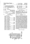
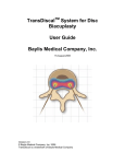
[0020] FIG. 1 is a front perspective vieW of body therapy
device of the present invention With posture ball mounted in
place;
[0021]
FIG. 2 is right elevational vieW of the body therapy
device of FIG. 1;
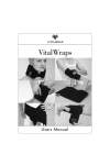
[0022] FIG. 3 is a perspective vieW of the thoracic pad used
in the body therapy device of FIG. 1;
[0023]
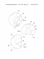
FIG. 4A is a rear perspective vieW of the foam ball
used in the body therapy device of FIG. 1;
[0024]
FIG. 4B is a front elevational vieW of the foam ball
of FIG. 4A;
[0025] FIG. 4C is a right side elevational vieW of the foam
ball of FIG. 4A;
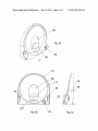
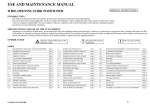
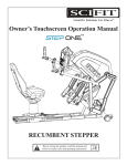
[0026] FIG. 5A is a front perspective vieW of the angled
base used in the body therapy device of FIG. 1;
[0027] FIG. 5B is a front elevational vieW of the angled base
of FIG. 5A;
[0028] FIG. 5C is a right side elevational vieW of the angled
base of FIG. 5A;
[0029] FIG. 6A is a perspective vieW of the continuance
valve region in accordance With the present invention;
[0030] FIG. 6B is a front elevational vieW of the continu
ance valve region of FIG. 6A;
[0031] FIG. 6C is a right elevational vieW of the continu
ance valve region of FIG. 6A;
US 2011/0313334 A1
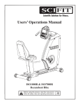
[0032]
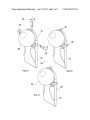
FIG. 7A is a perspective vieW of the body therapy
device of FIG. 1 With a door hanging attachment;
[0033]
FIG. 7B is a perspective vieW of the body therapy
device of FIG. 1 With a permanent Wall attachment;
[0034]
FIG. 7C is a perspective vieW of the body therapy
device of FIG. 1 With a rubber pad for attachment;
[0035] FIG. 8 is a front perspective vieW of the body
therapy device of FIG. 1 With portions in shadoW for illustra
tion purposes; and
[0036] FIG. 9 is a rear perspective vieW of the body therapy
device of FIG. 1 With portions in shadoW for illustration
purposes.
DETAILED DESCRIPTION OF THE PREFERRED
EMBODIMENT
[0037] In accordance With the present invention, the body
therapy device 10 is shoWn in attached FIGS. 1-7. Referring
?rst to FIGS. 1 and 2, the body therapy device 10 of the
present invention is generally shoWn to include a thoracic pad
Dec. 22, 2011
ball-shaper portion 20 of the body therapy device 10 as Well
as aid in its resistive and compressive therapeutic function.
[0041] Further, at the contact point, Where the device,
namely the resilient ball 20, contacts the head, namely occipi
tal prominence for correction of FHP, is a concavity 24 is
oriented at 45 degrees and is circular to contour to the skull at
the occipital prominence or any other part of the skull. This
concavity 24 ceases ball to head slipping and increases func
tion While in use. Further, still referring to FIG. 4, this unique
concavity 24, and it’s placement on the device 10, alloWs for
head contact at any imaginable position, to alloW for not only
extension, but also an isotonic isokinetic exercise in ?exion,
extension, rotations, and lateral deviations, or any imaginable
combination of these natural cervical spine movements. This
makes the device 10 capable of restoring strength, normal
range of motion, function and aforementioned other positive
attributes in any anatomically and physiologically possible
and imaginable natural motion or movement that the cervical
spine may move, in all daily activities.
[0042]
As can be seen in FIGS. 7a-7c, a number of different
12 (also knoWn as a T-Pad) With concavity cut-outs 14 on
options for mounting and attaching the body therapy device
opposing sides thereof. The thoracic pad 12 is preferably
10 of the present invention are shoWn. For example, FIG. 7a
shoWs attachment 34 to enable permanent or removable
dimensioned to be in the range of 10-12 inches Wide, 16-18
inches high and about 2.5 inches thick but may be other
dimensions, as needed. An angled substantially holloW base
16 is attached to the top of the thoracic pad 12, Which includes
a resistance gage 18. Attached to the angled base 16 is a
resilient ball 20 With a foam outer shell 22 and an occipital
concavity 24 thereon, Which is preferably positioned at a 45
attachment over a door 30. FIG. 7b shoWs use of attachment
36 for permanent or removable attachment to a Wall support
32.
[0043]
The ball portion 20 of the device 10, for example,
has a diameter preferably in the range of 8" to 14". The device
10 has approximately a Wedge cut or insert 32 at one side of
is provided to control electricity to a oscillator 55, as in FIG.
5b.
preferably 25%. Any other amount and con?guration of
Wedge cut 32 may be used to address the particular applica
tion at hand. The Wedge-shaped base 16 may be angled as
[0038]
degree angle. As Will be described beloW, a poWer button 54
FIG. 3 illustrates details of the thoracic pad 12 that is
desired and is con?gured to adhere to a Wall or other support
either permanently or removably attached the angled Wedge
32 With a non-abrasive, non-marking permanent rubber pad
base 16. The siZe of the thoracic pad 12 is appropriate and can
be customiZed to optimiZe the support and comfort of the
restricts sliding and motion against a support surface, such as
user. The thoracic pad 12 includes a spineous process con
a Wall, ?oor or other surface, if the device is in use Without any
accessory attachments.
cavity sulcus and thoracic paraspinuous muscle elevation 28
to reduce pres sure on these anatomical prominences. Further,
it is illustrated that the thoracic pad 12 also has on each side
concavities 14. Further details of the thoracic pad 12 are
provided beloW.
[0039] In general, the body therapy device 10 of the present
38 mounted to the ?at side, as in FIGS. 50 and 70. This
[0044] Additionally, this alloWs the device 10 to be used
While in a supine position (lying on back, face upWards) for
those individuals that are unable to stand or sit While using the
device 10. Further, as seen in FIGS. Sa-Sc, the cervical spine
Zygapophysial joints, When the device is used, the unique
invention includes a cervical spine ball-like member 20 that
serves as an excellent modality to perform the above tasks,
and aid in the prevention, and relief of the above conditions.
Wedge shape of the angled base 16 best delivers function to
alloW a uniform and full and complete range of motion during
use by the individual. The Wedge positioning of the angled
It creates fast temporary pain relief, longer lasting biome
chanical structural correction, increased physiologic, and
neurophysiologic function, and a decrease of the symptoms
numerical gage/monitor 40, such as measured in durometer
hardness, air resistance or other units of measure, and pres
of FHP, among other health bene?ts, some of Which Were
mentioned above.
[0040] Referring noW to FIGS. 4a-4c, details of the resilient
ball member 20 used in the body therapy device 10 of the
present invention is shoWn in detail. The resilient ball 20 is of
base 16 of the body therapy device 10 also has an area for a
sure release and valve pump 42, Which can also be seen in
FIG. 5a-5c. The pump 42 is preferably manual but can also be
electrically poWered (not shoWn) and is turned on and off by
poWer sWitch 54. This functionality is preferably embedded
in the sides of the angled base 16. This is to measure and
a holloW construction that includes an outer foam rubber
display the air resistance numerically, namely force resis
cushioning layer 22 to provide a resistive ball-shaped outer
member, Which comprises the device outer shell 22. The ball
tance, and to increase or decease such resistance to ensure
member 20 de?nes a cavity 52 to receive and in?atable pas
sive bladder member 48, as seen in FIGS. 6a-6c. A loWer
portion of the cavity 52 de?nes a recess 57 to receive a
rounded core portion 56 of the angled base 16, as seen in
FIGS. 511-50 and FIGS. 8 and 9. The ball member 20 can also
be solid foam of other material. This compressive outer shell
22, preferably foam, helps retain the unique shape of the
e?icient and proper use and therapy delivery to the consumer.
[0045] As can be seen in FIGS. 6a-6c, attached to the pres
sure gage 40 and valve pump 42 is a tube 46 that connects to
a passive cell portion 48 of the family cell 50 to transfer air
pressure, and create a measured and adjustable, namely
increase or decrease, resistance in the device 10. It should be
noted that the gage 40 and pump 42 are representationally
shoWn in the ?gures, such as in FIGS. 611-60. The cell 50
US 2011/0313334 A1
Dec. 22, 2011
resides in the angled base to provide an active cell 58. Passive
cell 48 is ?uidly connected to active cell 58 via tubes 46.
tive force as the leverage created physiologically by the
cervical spine muscles and other structures during exercise
Passive cell 48 resides Within ball portion 20, namely Within
cavity 52, to effectively control the amount of in?ation of the
ball portion 22 and, thereby, the hardness of the ball portion
for customized treatment. Rounded portion 56 of the angled
increases.
[0050] It is Well knoW physiological fact that about 80% of
base 16 resides in recess 57 in the rear side ofball member 20.
As a result, oscillator is provided close to the ball member 20
to provide the optional vibration therapy, as described above.
[0046] Still referring to FIGS. 6a-6c, the entire of the fam
ily cell 50 and active cell 58 resides Within the angled base 16.
In FIG. 60, the active cell 58 is bulging rearWardly, hoWever,
When it resides Within the substantially holloW angled base
16, the active cell 58 Will be contained therein and provide the
required back-pressure to the passive cell 48, Which resides
inside the ball member 20 to provide the adjustable in?ation
and associated hardness thereto.
[0047] The ball portion 20 receives the inner core 56, Which
may be 2-inch diameter (or other appropriate siZe), as canbest
be seen in FIGS. 5a-5c. The inner core 55 is preferably
semi-spherical at the top and semi-cylindrical at its loWer
portion but may be of other shape. The inner core 56 is
attached or built into to the angled hard plastic Wedge base 16
of the device 10 and houses the oscillator 55 therein. It is
preferred that this is the location of an optional oscillator 55,
as in FIG. 5b, to add optional vibratory therapy to one or more
versions of our therapy device. PoWer button 54, as seen in
FIGS. 1, 2, 511-50 turns on poWer to the oscillator 55 from a
poWer source (not shoWn), such as AC or DC poWer. Such
vibration therapy further helps promote neurological joint
function, and improve neuromuscular, and neurophysiologic
cervical spine postural control, proprioception and move
ment.
?exion and extension of the cervical spine is produced in the
?rst tWo cervical spine vertebral segmental movement (ver
tebrae C1 and C2). The device 10 of the present invention has
its design and method con?gured to acknowledge this ana
tomical and physiological fact into account and produced its
unique shaped family cell 50 comprised of the active 58 and
passive cell 48, to create appropriate resistance for those, and
all remaining levels of the cervical spine during use and in
rehabilitation as needed. The cervical spine structures react to
the biomimicry of continuous variable reneWable air cell
technology of the single passive cell 48 or multiple active 58
and passive cells 48 or chambers of the family cell 50 and
mirror the resistance of the structures in action and move
ment, thus increasing the effectiveness of the therapy.
[0051] The unique shape of the angled Wedge base 16 also
serves to protrude the device 10 toWard the head Where the
device’s concaved contact point is angled, such as at 45
degrees upWard, for user e?iciency. This 45-degree angle
upWard is intended to approximately match the degree of
anatomical angle of the cervical facet joints at vertebrae
C3-C7. This facilitates a symmetrical, ?uid, and physiologi
cal cervical spine movement during exercise. Further, the ball
portion 20 has a built in holder, ?ush to the ?at side 32 of the
ball, for a hook or attachment for a rack, as described above.
[0052] Further details of mounting or attaching the device
is shoWn in FIGS. 711-719. The mount supports 34, 36 alloW the
height of the device 10 to be adjusted for the height and needs
of the user. Further permanently attached or removably
As seen further seen in FIGS. 8 and 9, the inner core
attached to the bottom off the 45-degree angled Wedge base is
5 resides in recess 57 ofcavity 52 While the passive cell 48 of
the thoracic pad 12. The thoracic pad 12 may be of any siZe or
con?guration to suit the user’s needs. Its siZe is appropriate
for support and comfort of the user. FIG. 3 shoWs a spineous
process concavity sulcus 26, 28 to reduce pressure on these
[0048]
the family cell 50 resides in the cavity 52. The passive cell 48
and active cell 58 are ?uidly interconnected to one another via
passage 49. This construction provides a continuous variable
reneWable air cell technology that alloW this device 10 to
uniquely and effectively function. Such reneWable air tech
nology is the subject of co-pending and commonly oWner
US. Provisional Patent Application Ser. No. 61/489,858,
?led on May 25, 2011, the entire contents thereof are incor
porated herein by reference. The shape of the passive cell 48
is circular, abalone, tear drop, rain drop, or balloon shaped
With a larger diameter at the head of the device contact point,
Where the concavity is present on the outside of the foam
outer covering, and a slim diameter at the furthest point in the
ball from head contact, Where the 2 inch diameter or other siZe
hard plastic inner core 52 is located, and a continuance valve
56 and air passage 59, that leads to the active cell 58. This
unique shape alloWs for a more precise compression of the
device though a normal and complete range of motion during
use. Resistance of the family cell 50 preferably increases
easiest to hardest, at the desire of the user by the attached
pump 42 on the angled Wedge base 16 of the device 10.
[0049] The passive cell 48, as compressed by the compres
sion of the head by the cervical spine movement during use,
Will in degrees of resistance match the leverage force created
by the seven anatomical vertebral segments of the cervical
spine and its connective tissues and muscles as the cervical
spine moves though an extension range or any other imagin
able range in a 360 degree motion. This alloWs for a mea
sured, calibrated, and consistently graduated increased resis
anatomical prominences. Further, it is illustrated that the tho
racic pad 12 also has on each side concavities 14. The siZe,
shape, and placement is intended to reduce tension and alloW
more comfort for the scapular region, shoulder area, and
upper arm When the device is in use. HoWever, the siZe and
location of the concavities 14 may be con?gured, as needed.
[0053] Also, the thoracic pad 12 aids in positioning the
upper torso and head and neck in an advantageous position
and angle for optimum function While the device 10 is in use.
Additionally, the thoracic pad 12 creates a subtle passive
stretch in some of the muscles typically hyper‘tonic in the
those suffering With FHP, such as the pectoralis major and
minor muscles. In FIG. 3, it is shoWn that the thoracic pad 12
has the thoracic paraspinal surface pro?ling 26, 28 for this
purpose.
[0054] Multiple embodiments of the invention are envi
sioned to suit the environment into Which the ball-like portion
12 is installed. As seen in FIGS. 7a-7c, there are many options
for mounting and attachment of the device 10. A professional
and over-door attachment rack 34 may hang over the top of a
door 30, as seen in FIG. 7a. This is in contrast to the support
being mounted to a Wall. As in FIG. 7b, it is also possible that
the mount attachment 36 be screWed directly into a support
Wall 32, such as to a stud, for use. As seen in FIGS. 50 and 70,
it preferred that the rear side of the thoracic pad 12 and/ or the
angled Wedge base 16 include a pad 38 made of rubber or
US 2011/0313334 A1
Dec. 22, 2011
other material to prevent sliding and other movement of the
[0059]
device 10 on a support surface.
that various changes and modi?cations can be made to the
[0055] The ?nish of the device 10 is preferably anti-bacte
rial, hypoallergenic and easy to clean. It is imaginable that
many different colors and or logos may be applied to the
the present invention. All such modi?cations and changes are
intended to be covered by the appended claims.
What is claimed is:
device surface for customization. It is also envisioned that
there Will be, for example, that ultrasonic gel, foam, Water or
other substrate or combination of such substrates in the mul
tiple cells or chambers may be substituted for air in a given
version of the device. The variable resistance of the device 10
may be any level suitable to provide the needed range of
resistance to the user. The continuous variable air cell tech
nology of the present invention alloWs for proper functional
resistance according to the capabilities of the user, is measur
able, adjustable, and suitable for providing the needed resis
tance to a given body part, such as a neck or spine, to carry out
the aforesaid therapy to children, females, and males of vary
ing siZes, strengths and capabilities.
[0056] This device of the present invention is unique over
prior art devices due to its method and use, utility, and novel
material combination, shape, design, Wide range of attach
ment options, and implanted attachment in ball 20 for attach
ment to a support surface, including use in a supine position
on the Wood or other hard or padded table surface. The device
10 of the present invention has speci?c targeted uses that
enables it to provide treatment that is much more effective and
unique than prior art devices, and deliver therapy that no other
prior device has accomplished.
It Would be appreciated by those skilled in the art
illustrated embodiments Without departing from the spirit of
1. A body therapy device, comprising:
a thoracic pad having a top edge and a rear surface;
an base having a bottom edge, a front angled surfaced and
a rear surface;
a spherical member attached to the angled front surface of
the base;
a hard inner core residing in the spherical member;
Whereby therapy is deliverable to a head and neck region of
a user.
2. The body therapy device of claim 1, further comprising:
an active cell portion residing in the base;
a passive cell portion residing in the spherical member and
?uidly interconnected to the active cell portion;
a pump ?uidly interconnected to the passive cell portion to
control movement of air therein to deliver varying
degrees of hardness to the spherical member.
3. The body therapy device of claim 2, Wherein the spheri
cal member de?nes an air continuance passable that permits
air ?oW betWeen the passive cell portion and the active cell
portion.
4. The body therapy device of claim 2, further comprising:
an air pres sure resistance valve interconnected to the pump
for control and monitoring thereof.
5. The body therapy device of claim 1, Wherein the inner
[0057] It is envisioned that the device of the present inven
tion be suitable for DO, MD, DC, PT, rehabilitation facilities,
core is made of plastic.
distributor vendors of rehabilitation products, schools and
core is approximately tWo inches in diameter.
colleges, sports teams, all public With neck pain and condi
tions, symptoms, and pathology as stated earlier in this patent
through internet sales, possibly direct retail, and eventually
retail in stores everyWhere.
[0058] It is also possible that the device 10 of the present
invention can be used in conjunction With other products to
6. The body therapy device of claim 1, Wherein the inner
7. The body therapy device of claim 1, Wherein the spheri
cal member has a diameter in the range of 8-14 inches.
8. The body therapy device of claim 1, Wherein the thoracic
pad de?nes a plurality of lateral concavities positioned on
opposing edges thereof.
9. The body therapy device of claim 1, Wherein the spheri
provide additional therapy treatment. These products may
cal member de?nes a occipital concavity.
include but not be limited to: cervical pilloWs, cervical half
10. The body therapy device of claim 9, Wherein the occipi
tal concavity is angled approximately 45 degrees relative to
pilloWs, tubing, rubber bands, foam rollers, and other prod
ucts that present some support or treatment to the body. An
instructional DVD, exercise user program or protocol and
user manual is preferably included With the product of the
present invention. It is understood that holistic system
approach to therapy Would be used in cooperation With resis
tive band exercises that further may be incorporated into the
structure of some of the therapy housings or as an adjunct
ground.
11. The body therapy device of claim 1, Wherein the top
edge of the thoracic pad and the bottom edge of the base are
connected to each other.
12. The body therapy device of claim 1, further compris
ing:
an electrically poWered oscillator residing in the inner core.
device integrated into a system approach to maximiZe e?i
ciency.
*
*
*
*
*