1
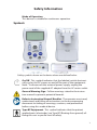
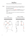
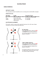
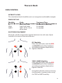
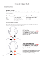
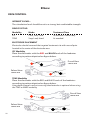
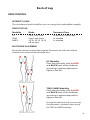
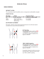
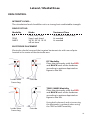
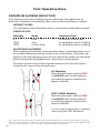
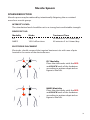
NexWave
User’s Manual
1
NexWave
Table of Contents
Contact Information / Customer Service / Supplies / Support
4
About the NexWave5
Safety Information6
Electrodes and Lead Wires Setup9
Programming Instructions12
Preprogrammed Modes13
Controls15
Operating Instructions16
Protocols17
Indications, Contraindications and Warnings
31
Precautions and Adverse Reactions
40
Troubleshooting41
Specifications and Accessories42
Electrodes, Batteries, and Cleaning43
Warranty44
3
Zynex® Medical
Contact Information
CUSTOMER SERVICE866-940-7030
Supplies:
To order more electrodes or other accessories
Technical Support:
Questions or problems with using your device
Device Return:
Order a postage paid return envelope to return your
device at no charge
MAIN OFFICE800-495-6670
303-703-4906
Billing Questions:
Questions regarding insurance benefits and
covered benefits for Durable Medical Equipment
(DME) or questions about an Explanation of
Benefits form you received in the mail.
FAX NUMBER800-495-6695
303-347-9153
MAILING ADDRESS
Zynex Medical, Inc.
9990 Park Meadows Drive
Lone Tree, CO 80124-6739
USA
[email protected]
WEBSITEwww.zynex.com
European Representative
Zynex Europe
Fælledvej 1, Box 19 BDO
DK-5100 Odense C
Denmark
4
0470
About the NexWave
The NexWave is a multiple-mode stimulator which allows users a choice of
treatment options. This device incorporates Interferential Current (IFC), Transcutaneous Electrical Nerve Stimulation (TENS), and Neuromuscular Electrical
Stimulation (NMES).
Interferential Current (IFC)
The left channel (channel 1) produces a signal at a frequency of 4000 Hz. A
slightly higher frequency (4001-4128 Hz) is produced by the right channel
(channel 2). When applied to the skin, the signals from the two channels “interfere” with each other, and create a difference frequency which is felt during
treatment. The skin is 100 times less resistant to electrical stimulation using
this method. Consequently more of the stimulation energy reaches the nerve
and muscle fibers and hence becomes more productive. With more stimulation reaching the affected area, IFC is recommended to be applied 3-4 times
a day for 30-40 minutes per treatment. IFC therapy requires the use of both
channels (four electrodes).
Transcutaneous Electrical Nerve Stimulation (TENS)
TENS delivers electrical impulses through the skin in the range of 1-125 Hz.
TENS treatments can range from 10 minutes to many hours and can be applied as needed for pain relief. Patients can use one or two channels (two or
four electrodes) for TENS therapy.
Neuromuscular Electrical Stimulation (NMES)
NMES delivers electrical impulses to muscular motor points at a frequency of
35 Hz. The output is set to a level which causes muscular contraction. These
impulses are turned on for a period of 10 seconds, and turned off for a period
of 10 seconds, 20 seconds, or 30 seconds. The outputs ramp up for 3 seconds,
remain at the desired level for 10 seconds, ramp down for 1 second, and
remain off for 10, 20, or 30 seconds. Recommended use is 3-4 times per day
for 20-30 minutes per treatment. Patients can use one or two channels (two or
four electrodes) for NMES therapy.
Important: This device must be ordered or prescribed by a licensed physician.
5
Safety Information
Equipment Classification
As per the International Electrotechnical Commission standard IEC
60601-1, and the European standard EN 60601-1, Medical Electrical
Equipment, General Requirements for Basic Safety and Essential Performance, the NexWave is classified as follows:
· Type BF Equipment
A Type BF piece of equipment is one that provides a particular
degree of protection against electric shock, particularly regarding allowable leakage current. Type BF applied part is one that is
floating above ground and is isolated from all other parts of the
equipment.
· Medical Device Directive (MDD) Classification
The NexWave a Class IIa medical device per the European Medical
Device Directive.
· Internally Powered Equipment
When the NexWave is powered by the internal, 9 VDC, MN1604,
battery it is classified as Internally Powered Equipment.
· Class II Medical Equipment
When powered by the external, 12 VDC, medical grade, power
supply, the NexWave is classified as Class II Medical Electrical (ME)
Equipment. Note: When the external power supply is connected
to the NexWave device, the power supply is considered part of
the ME equipment.
· Electromagnetic Compatibility
Conforms to IEC 60601-1-2.
· Temperature
Operating temperature range: 0° - 40° C (32° - 104° F)
Storage temperature range: -20° - 70° C (-4° - 158° F)
· Water Ingress
Ordinary equipment. This device does not have protection
against ingress of water.
· Flammable Anesthetics
This device is not suitable for use in the presence of a flammable
anesthetic mixture with air, or in the presence of a flammable
anesthetic mixture with oxygen or nitrous oxide.
6
Safety Information
Mode of Operation
This device is suitable for continuous operation.
Symbols
Safety symbols shown on the device above are defined below.
On/Off. This symbol indicates that the labeled switch electronically cycles the DC power on and off for part of the equipment.
Note: To disconnect the external power supply, unplug the
power cord of the supplied AC adapter from the AC mains outlet
General Warning Sign. Follow warnings stated in the instruction manual to prevent potential hazards.
Refer to Instruction Manual/Booklet. The operator must read,
understand, and follow all instructions in the accompanying
document including all warnings, cautions, and precautions
before using this medical device.
Type BF Equipment. This symbol indicates that the patient
applied parts (electrodes) are Type BF (floating from ground) offering the user a specific level of safety.
7
Waste Electrical and Electronic Equipment (WEEE). This
product may contain substances known to be hazardous to the
environment or to human health. It should be disposed of properly (for example, at your local waste collection administration or
recycling plant) and in accordance with local ordinances.
Service and Calibration
· Do not remove the cover. There are no user serviceable parts.
Refer all service to authorized personnel. No modification of the
equipment is allowed.
· No preventative inspections are required. Factory testing and
calibration ensure equipment accuracy and response. Contact
Zynex Medical for factory re-calibration if necessary.
8
NexWave
Electrode and Lead Wire Setup
Step 1
Open electrode package and remove electrodes from package.
Keep electrodes on plastic backing.
Note: Only Zynex Medical electrodes are approved for use with
the NexWave. P/N 300027 are provided standard. Sterile electrodes, P/N 300100, are optionally available (for U.S. only). See
Accessories on page 42.
Electrode Connector
Plastic Backing
Electrode
Step 2
Insert lead wire pin connectors into electrode connectors as
shown below. RED lead wire connectors on one side and BLACK
lead-wire connectors on the other side.
IFC modality requires all 4 electrodes (2 channels)
TENS and NMES modalities can
use 2 electrodes (1 channel) or 4
electrodes (2 channels)
9
NexWave
Electrode and Lead Wire Setup (continued)
Step 3
Remove each electrode from the plastic backing and place on
the treatment site according to the type of modality selected.
Electrode Arrangement
When using the IFC modality, RED and BLACK lead wires must
be placed in a crisscrossed pattern as shown in the diagram
below.
TENS or NMES shall not be crisscrossed and can be placed in a
side-by-side pattern.
IFC
Crisscrossed Pattern
10
TENS or NMES
Up and Down Pattern
NexWave
Electrode and Lead Wire Setup (continued)
Step 4
Plug lead wires into the top of the device. The IFC modality
requires both sets of lead wires to be connected (channel 1 and 2).
TENS and NMES can use 1 set (Channel 1) or 2 sets
(Channel 1 and 2) of lead wires.
Step 5
Proceed to page 16 to start treatment or page 12 to program
device.
Channel 1
Channel 2
11
NexWave
Device Programming Instructions
Turn device on by pressing the black On/Standby button
1.
Select desired Modality by pressing the “IFC”, “TENS”, or “NMES”
button once.
2.
Continue to press the selected modality button until arrow is next to
desired program.
3.
Press Treatment Timer button until desired treatment time is set on
screen.
Device is now ready to use.
On / Off
Button
Modality
Buttons
Treatment
Timer Button
12
NexWave
Preprogrammed Modes
Interferential Current (IFC)
Mode
Description
Low-High
The frequency of channel 2 sweeps between 4001 Hz
and 4128 Hz every 15 seconds, while the channel 1
frequency remains fixed at 4000 Hz.
Low
The frequency of channel 2 sweeps between 4001 Hz
and 4010 Hz every 15 seconds, while the channel 1
frequency remains fixed at 4000 Hz.
Combo
Combo consists of three 2 minute cycles which repeat
over the duration of the treatment.
1st cycle - Low Mode: as described above.
2nd cycle - High Mode: like Low Mode, but channel 2
sweeps between 4064 Hz and 4128 Hz.
3rd cycle - Muscle Mode: The frequency of channel 2 is
fixed at 4064 Hz, and the frequency of channel 1 is fixed
at 4000 Hz. Both channels are cycled on and off simultaneously at 6 second intervals.
Transcutaneous Electrical Nerve Stimulation (TENS)
Mode
Description
Sweep
The frequency is decreased linearly from 125 Hz to 11
Hz over a 4 second span. During this time, the pulse
width is increased linearly from 120 µs to 300 µs. Then
the frequency is decreased from 10 Hz to 1 Hz over a
two second span. The pulse width is constant at 300 µs.
Then the frequency is increased linearly from 11 Hz to
125 Hz over a four second span. During this time, the
pulse width is decreased linearly from 300 µs to 120 µs.
Lmd
Frequency sweeps between 66.7-100 Hz and back again
over 12 seconds. Pulse width linearly decreases to 150
µs when frequency is sweeping up and increases back
up to the nominal pulse width of 300 µs when frequency is sweeping down.
Hmd
Same as Lmd, but with a frequency shift interval of 2
seconds.
13
Neuromuscular Electrical Stimulation (NMES)
14
Mode
Description
30:10
Preset 10 seconds on and 30 seconds off time, 35 Hz
frequency, 480 µs pulse width, 3 second ramp-up,
1 second ramp-down, both channels cycle simultaneously.
20:10
Same as above, but with 20 second off time.
10:10
Same as above, but with and 10 second off time.
NexWave
Device Controls
Display
Lead Wire Connection
Channel 1
Lead Wire Connection
Channel 2
Uses electricity from
wall socket instead of
9 V battery
A/C Adapter
Input
Turns Unit On/Off
On/Off Button
Channel 1 Intensity Control
Channel 2 Intensity Control
Up and Down Button
Up and Down Button
Unlock Button Controls
IFC, TENS, NMES
Unlock Button
Modality Buttons
Treatment Timer
Treatment Timer Button
15
NexWave
Device Operating Instructions
Start Treatment:
Before starting treatment electrodes must be placed on the treatment site and
lead wires and electrodes connected to the device. See pages 9-11 and 17-30 for
examples.
1.
Turn NexWave on by pressing On/Standby button once
2.
Increase intensity by pressing Channel 1 Up button until a strong
but comfortable stimulation level is felt. Repeat for Channel 2 if both
lead wires are attached and device is in TENS or NMES mode.
3.
Once desired level of stimulation is set, the unit will automatically
shut off at the preset treatment time shown on the display. If Treatment Timer has been set to No Timer then the device will need to
be shut off manually. Refer to Programming Instructions on page 12 to
adjust Treatment Timer.
4.
To turn off device manually, press the On/Standby button.
Note: Intensity level can be increased or decreased with either Channel 1 or Channel 2
Up and Down buttons when device is set to IFC Mode. If “Check Connections!” message is
displayed on the screen, see “Display Alerts” below.
During Treatment:
IMPORTANT: Button controls lock after 20 seconds of inactivity. To unlock
button controls, press Unlock button.
Increase Intensity:
To increase intensity press the Up Intensity button for either channel until the desired
level of stimulation is felt. While in IFC mode, pressing either channel Up Intensity button will increase the stimulation level.
Decrease Intensity:
To decrease intensity press the Down Intensity button for each channel until desired
level of stimulation is felt. While in IFC mode, pressing either channel Down Intensity
button will decrease the stimulation level.
Display Alerts:
Check Connections: Lead wire(s) and/or electrode(s) may not be attached properly.
Check all connections and try again (see page 41). If problem persists, call Technical
Support (see page 4).
Low Battery: Replace battery immediately or connect the A/C adapter.
16
Locked: Stimulation level and mode cannot be changed until Unlock button is pressed.
Radicular Back Pain-Sciatica
PAIN CONTROL
INTENSITY LEVEL:
The stimulation level should be set to a strong, but comfortable strength.
DEVICE SET-UP:
Modality
Mode
Treatment Time
TENS
Swp, Lmd, Hmd
As needed
ELECTRODE PLACEMENT Option 1
Electrodes should follow the dermatomal pattern related to the affected nerve
root within the spinal segments involved.
TENS Modality
Place the electrodes with the RED and
BLACK ends of the leadwires according to
pattern depicted on figure to the left.
ELECTRODE PLACEMENT Option 2
Electrodes should follow the dermatomal pattern related to the affected nerve
root within the spinal segments involved. OVERLAPPING Techniques may vary.
17
Lumbar Back
PAIN CONTROL
INTENSITY LEVEL:
The stimulation level should be set to a strong, but comfortable strength.
DEVICE SET-UP:
Modality
Mode
IFC
LoHi, Low, Cmb
TENS
Swp, Lmd, Hmd
NMES
30:10, 20:10, 10:10
off:on time
Treatment Time
40 minutes 4 times/day
As needed
As needed
ELECTRODE PLACEMENT
Electrodes should surround the targeted treatment site with area of pain
located in the center of the electrode area.
IFC Modality
Place the electrodes with the RED
and BLACK ends of the leadwires
according to pattern depicted on
figure to the left.
TENS / NMES Modality
Place the electrodes with the RED
and BLACK ends of the leadwires
according to pattern depicted on
figure to the left.
Using both channels and crisscrossing
the electrodes is optional when using
the TENS or NMES modality.
18
Thoracic Back
PAIN CONTROL
INTENSITY LEVEL:
The stimulation level should be set to a strong, but comfortable strength.
DEVICE SET-UP:
Modality
Mode
IFC
LoHi, Low, Cmb
TENS
Swp, Lmd, Hmd
NMES
30:10, 20:10, 10:10
off:on time
Treatment Time
40 minutes 4 times/day
As needed
As needed
ELECTRODE PLACEMENT
Electrodes should surround the targeted treatment site with area of pain
located in the center of the electrode area.
IFC Modality
Place the electrodes with the RED
and BLACK ends of the leadwires
according to pattern depicted on
figure to the left.
TENS / NMES Modality
Place the electrodes with the RED
and BLACK ends of the leadwires
according to pattern depicted on
figure to the left.
Using both channels and crisscrossing
the electrodes is optional when using
the TENS or NMES modality.
19
Cervical / Upper Back
PAIN CONTROL
INTENSITY LEVEL:
The stimulation level should be set to a strong, but comfortable strength.
DEVICE SET-UP:
Modality
Mode
IFC
LoHi, Low, Cmb
TENS
Swp, Lmd, Hmd
NMES
30:10, 20:10, 10:10
off:on time
Treatment Time
40 minutes 4 times/day
As needed
As needed
ELECTRODE PLACEMENT
Electrodes should surround the targeted treatment site with area of pain
located in the center of the electrode area.
IFC Modality
Place the electrodes with the RED
and BLACK ends of the leadwires
according to pattern depicted on
figure to the left.
TENS / NMES Modality
Place the electrodes with the RED
and BLACK ends of the leadwires
according to pattern depicted on
figure to the left.
Using both channels and crisscrossing
the electrodes is optional when using
the TENS or NMES modality.
20
Shoulder
PAIN CONTROL
INTENSITY LEVEL:
The stimulation level should be set to a strong, but comfortable strength.
DEVICE SET-UP:
Modality
Mode
IFC
LoHi, Low, Cmb
TENS
Swp, Lmd, Hmd
NMES
30:10, 20:10, 10:10
off:on time
Treatment Time
40 minutes 4 times/day
As needed
As needed
ELECTRODE PLACEMENT
Electrodes should surround the targeted treatment site with area of pain
located in the center of the electrode area.
IFC Modality
Place the electrodes with the RED
and BLACK ends of the leadwires
according to pattern depicted on
figure to the left.
TENS / NMES Modality
Place the electrodes with the RED
and BLACK ends of the leadwires
according to pattern depicted on
figure to the left.
Using both channels and crisscrossing
the electrodes is optional when using
the TENS or NMES modality.
21
Elbow
PAIN CONTROL
INTENSITY LEVEL:
The stimulation level should be set to a strong, but comfortable strength.
DEVICE SET-UP:
Modality
Mode
Treatment Time
IFC
TENS
LoHi, Low, Cmb
Swp, Lmd, Hmd
40 minutes 4 times/day
As needed
ELECTRODE PLACEMENT
Electrodes should surround the targeted treatment site with area of pain
located in the center of the electrode area.
IFC Modality
Place the electrodes with the RED and BLACK ends of the leadwires
according to pattern depicted on figure below.
Dorsal View
same arm
Palmar View
same arm
TENS Modality
Place the electrodes with the RED and BLACK ends of the leadwires
according to pattern depicted on figure below.
Using both channels and crisscrossing the electrodes is optional when using
the TENS or NMES modality.
Dorsal View
same arm
Palmar View
same arm
22
Wrist
PAIN CONTROL
INTENSITY LEVEL:
The stimulation level should be set to a strong, but comfortable strength.
DEVICE SET-UP:
Modality
Mode
Treatment Time
IFC
TENS
LoHi, Low, Cmb
Swp, Lmd, Hmd
40 minutes 4 times/day
As needed
ELECTRODE PLACEMENT
Electrodes should surround the targeted treatment site with area of pain
located in the center of the electrode area.
IFC Modality
Place the electrodes with the RED and BLACK ends of the leadwires
according to pattern depicted on figure below.
Palmar View
Dorsal View
same arm
same arm
TENS Modality
Place the electrodes with the RED and BLACK ends of the leadwires
according to pattern depicted on figure below.
Using both channels and crisscrossing the electrodes is optional when using
the TENS or NMES modality.
Palmar View
same arm
Dorsal View
same arm
23
Hip
PAIN CONTROL
INTENSITY LEVEL:
The stimulation level should be set to a strong, but comfortable strength.
DEVICE SET-UP:
Modality
Mode
IFC
LoHi, Low, Cmb
TENS
Swp, Lmd, Hmd
NMES
30:10, 20:10, 10:10
off:on time
Treatment Time
40 minutes 4 times/day
As needed
As needed
ELECTRODE PLACEMENT
Electrodes should surround the targeted treatment site with area of pain
located in the center of the electrode area.
IFC Modality
Place the electrodes with the RED
and BLACK ends of the leadwires
according to pattern depicted on
figure to the left.
TENS / NMES Modality
Place the electrodes with the RED
and BLACK ends of the leadwires
according to pattern depicted on
figure to the left.
Using both channels and crisscrossing
the electrodes is optional when using
the TENS or NMES modality.
24
Back of Leg
PAIN CONTROL
INTENSITY LEVEL:
The stimulation level should be set to a strong, but comfortable strength.
DEVICE SET-UP:
Modality
Mode
IFC
LoHi, Low, Cmb
TENS
Swp, Lmd, Hmd
NMES
30:10, 20:10, 10:10
off:on time
Treatment Time
40 minutes 4 times/day
As needed
As needed
ELECTRODE PLACEMENT
Electrodes should surround the targeted treatment site with area of pain
located in the center of the electrode area.
IFC Modality
Place the electrodes with the RED
and BLACK ends of the leadwires
according to pattern depicted on
figure to the left.
TENS / NMES Modality
Place the electrodes with the RED
and BLACK ends of the leadwires
according to pattern depicted on
figure to the left.
Using both channels and crisscrossing
the electrodes is optional when using
the TENS or NMES modality.
25
Anterior Knee
PAIN CONTROL
INTENSITY LEVEL:
The stimulation level should be set to a strong, but comfortable strength.
DEVICE SET-UP:
Modality
Mode
IFC
LoHi, Low, Cmb
TENS
Swp, Lmd, Hmd
NMES
30:10, 20:10, 10:10
off:on time
Treatment Time
40 minutes 4 times/day
As needed
As needed
ELECTRODE PLACEMENT
Electrodes should surround the targeted treatment site with area of pain
located in the center of the electrode area.
IFC Modality
Place the electrodes with the RED
and BLACK ends of the leadwires
according to pattern depicted on
figure to the left.
TENS / NMES Modality
Place the electrodes with the RED
and BLACK ends of the leadwires
according to pattern depicted on
figure to the left.
Using both channels and crisscrossing
the electrodes is optional when using
the TENS or NMES modality.
26
Lateral / Medial Knee
PAIN CONTROL
INTENSITY LEVEL:
The stimulation level should be set to a strong, but comfortable strength.
DEVICE SET-UP:
Modality
Mode
IFC
LoHi, Low, Cmb
TENS
Swp, Lmd, Hmd
NMES
30:10, 20:10, 10:10
off:on time
Treatment Time
40 minutes 4 times/day
As needed
As needed
ELECTRODE PLACEMENT
Electrodes should surround the targeted treatment site with area of pain
located in the center of the electrode area.
IFC Modality
Place the electrodes with the RED
and BLACK ends of the leadwires
according to pattern depicted on
figure to the left.
Inside View
Same Leg
Outside
TENS / NMES Modality
Place the electrodes with the RED
and BLACK ends of the leadwires
according to pattern depicted on
figure to the left.
Inside View
Same Leg
Outside
Using both channels and crisscrossing
the electrodes is optional when using
the TENS or NMES modality.
27
Ankle
PAIN CONTROL
INTENSITY LEVEL:
The stimulation level should be set to a strong, but comfortable strength.
DEVICE SET-UP:
Modality
Mode
Treatment Time
IFC
TENS
LoHi, Low, Cmb
Swp, Lmd, Hmd
40 minutes 4 times/day
As needed
ELECTRODE PLACEMENT
Electrodes should surround the targeted treatment site with area of pain
located in the center of the electrode area.
IFC Modality
Place the electrodes with the RED
and BLACK ends of the leadwires
according to pattern depicted on
figure to the left.
ACHILLES TENDON
28
TENS / NMES Modality
Place the electrodes with the RED
and BLACK ends of the leadwires
according to pattern depicted on
figure to the left.
Using both channels and crisscrossing
the electrodes is optional when using
the TENS or NMES modality.
ACHILLES TENDON
Inside View
Same Foot
Outside View
Same Foot
Inside View
Same Foot
Outside View
Same Foot
Inside View
Same Foot
Outside View
Same Foot
Inside View
Same Foot
Outside View
Same Foot
Foot
PAIN CONTROL
INTENSITY LEVEL:
The stimulation level should be set to a strong, but comfortable strength.
DEVICE SET-UP:
Modality
Mode
Treatment Time
IFC
TENS
LoHi, Low, Cmb
Swp, Lmd, Hmd
40 minutes 4 times/day
As needed
ELECTRODE PLACEMENT
Electrodes should surround the targeted treatment site with area of pain
located in the center of the electrode area.
IFC Modality
Place the electrodes with the RED
and BLACK ends of the leadwires
according to pattern depicted on
figure to the left.
TENS / NMES Modality
Place the electrodes with the RED
and BLACK ends of the leadwires
according to pattern depicted on
figure to the left.
Using both channels and crisscrossing
the electrodes is optional when using
the TENS or NMES modality.
29
Post-Operative Knee
PAIN RELIEF & EDEMA REDUCTION
Post-operative pain and swelling may be reduced by the application of
electrical stimulation immediately after surgery and continuing as needed.
INTENSITY LEVEL:
The stimulation level should be set to a strong, but comfortable strength.
DEVICE SET-UP:
Modality
Mode
Treatment Time
IFC
TENS
TENS
Cmb
Swp
Lmd or Hmd
40 minutes 4 times/day
As needed for pain & swelling
As needed for pain & swelling
ELECTRODE PLACEMENT
When applying electrodes in the operating room, sterile electrodes must
be used and placed away from incisions as shown below. Electrodes applied outside the operating room do not need to be sterile and should be
placed around the bandaged area in the pattern shown below.
Electrodes should surround the targeted treatment site with area of pain
located in the center of the electrode area.
IFC Modality
Place the electrodes with the RED
and BLACK ends of the leadwires
according to pattern depicted on
figure to the left.
TENS / NMES Modality
Place the electrodes with the RED
and BLACK ends of the leadwires
according to pattern depicted on
figure to the left.
Crisscrossing the electrodes is optional
when using the TENS Waveform.
30
Protocol based on the following study: The Effects of Home Interferential Therapy on Post-Operative Pain, Edema, and Range of
Motion of the Knee, by Gregg J. Jarit, MD, Karen J. Mohr, PT, SCS, Robert Waller, BS and Ronald E. Glousman, MD Published in Clinical Journal of Sports Medicine, 13:16-20 © 2003 Lippincott Williams & Wilkins, Inc, Philadelphia
Muscle Spasm
SPASM REDUCTION
Muscle spasm may be reduced by intentionally fatiguing the associated
muscle or muscle group.
INTENSITY LEVEL:
The stimulation level should be set to a strong, but comfortable strength.
DEVICE SET-UP:
Modality
Mode
Treatment Time
IFC
NMES
Cmb
10:10 off:on time
40 minutes 3 to 4 times/day
40 minutes 3 to 4 times/day
ELECTRODE PLACEMENT
Electrodes should surround the targeted treatment site with area of pain
located in the center of the electrode area.
IFC Modality
Place the electrodes with the RED
and BLACK ends of the leadwires
according to pattern depicted on
figure to the left.
NMES Modality
Place the electrodes with the RED
and BLACK ends of the leadwires
according to pattern depicted on
figure to the left.
31
NexWave
Indications for Use
Indications
·
·
Interferential Current (IFC)
Management and symptomatic relief of chronic intractable, posttraumatic and post-surgical pain.
This stimulator should only be used under supervision for adjunctive
therapy for the treatment of medical diseases and conditions.
Contraindications
·
·
·
This stimulator should not be used on patients with a cardiac
demand pacemaker.
Electrodes should not be placed so that current will be applied to the
carotid sinus (neck) region or transcerebrally (through the head).
This stimulator should not be used whenever pain syndromes are
undiagnosed until etiology is established.
Warnings
·
·
·
When using the separate external power supply, this medical electrical device does not incorporate a power switch to isolate the system
from the AC mains. Unplug the power cord of the AC adapter from
the AC mains outlet in order to positively disconnect from the AC
mains. Ensure that the AC outlet is easily accessible.
The device is capable of generating current densities for electrodes
exceeding 2 mA RMS/cm2 which may require special attention of the
operator.
Do not exceed 0.5 W/cm2 with recommended electrodes, assuming a
load of 1000 Ω.
· 1” round: Maximum stimulation setting = 50 mA
· 2” round: Maximum stimulation setting = 50 mA
· 2” square: Maximum stimulation setting = 50 mA
·
32
Output waveform/power information:
When delivering stimulation energy, the NexWave in IFC mode is a constant current output device. Therefore its output voltage, current, and
power are dependent upon the load as well as the pulse width and frequency of the output waveform. Using the supplied AC adapter to power
the unit, the maximum peak voltage that the NexWave can produce is
50 V (1000 Ω load). The maximum peak current that the NexWave can
produce is 50 mA (1000 Ω load). The maximum output power that the
NexWave can produce is 2.5 W per channel into a 1000 Ω load, 5 W total.
NexWave
Warnings
Interferential Current (IFC)
Warnings (Continued)
· Maximum peak output voltage (500 Ω load) = 25 V
· Maximum peak output current (500 Ω load) = 50 mA
· Maximum peak output voltage (1 KΩ load) = 50 V
· Maximum peak output current (1 KΩ load) = 50 mA
· Maximum peak output voltage (2 KΩ load) = 50 V
· Maximum peak output current (2 KΩ load) = 25 mA
· Frequency: 4000 Hz nominal
· Duty Cycle: 100%
· Maximum RMS voltage (500 Ω load) = 25 V
· Maximum RMS current (500 Ω load) = 50 mA
· Maximum output power (500 Ω load) = 1.25 W per channel
· Maximum RMS voltage (1 KΩ load) = 50 V
· Maximum RMS current (1 KΩ load) = 50 mA
· Maximum output power (1 KΩ load) = 2.5 W per channel
· Maximum RMS voltage (2 KΩ load) = 50 V
· Maximum RMS current (2 KΩ load) = 25 mA
· Maximum output power (2 KΩ load) = 1.25 W per channel
· The safety of Interferential devices for use during pregnancy or birth has
not been established.
· This device is not effective for pain of central origin.
(This includes headache.)
· This device should only be used under the continued supervision of a
trained physician.
· This device does not have curative value.
· This device offers symptomatic treatment such as suppressing the sensation of pain which would otherwise serve as a protective mechanism.
· The user must keep the device out of the reach of children.
· Electronic monitoring equipment (such as ECG monitors and ECG alarms)
may not operate properly when this device is in use.
· The long-term effects of chronic electrical stimulation are unknown.
· Stimulation should not be applied over the carotid sinus nerves,
particularly in patients with known sensitivity to the carotid sinus reflex.
· Stimulation should not be applied over the neck or mouth. Severe spasm
of the laryngeal and pharyngeal muscles may occur and the contractions
may be strong enough to close the airway or cause difficulty in breathing.
· Stimulation should not be applied transthoracically in that the introduction of electrical current into the heart may cause cardiac arrhythmias.
33
NexWave
Warnings
Interferential Current (IFC)
Warnings (Continued)
·
·
·
·
·
·
Stimulation should not be applied transcerebrally.
Stimulation should not be applied over swollen, infected, or inflamed
areas of skin eruptions, e.g. phlebitis, thrombophlebitis, varicose
veins, etc.
Stimulation should not be applied over, or in proximity to,
cancerous lesions.
The device is capable of generating currents and voltages in excess
of 10 mA RMS and 10 V RMS, respectively. A yellow LED indicator is
provided next to each lead wire connector to show that the unit is
delivering energy for any non-zero value of stimulation output
(1-50 mA).
Simultaneous connection of a patient to high frequency surgical
equipment may result in burns at the site of the stimulator electrodes
and possible damage to the stimulator.
Operations within close proximity (within one meter) of shortwave
or microwave therapy equipment may produce instability in the
stimulation output.
Safety References
Zynex® Medical, Inc. is only responsible for the safety, reliability and function
of the device when repairs and adjustments have been made by persons
authorized by Zynex® Medical, Inc., and the device is used in accordance with
the user’s manual. Repairs and technical safety tests shall only be performed
by authorized personnel.
34
NexWave
Indications for Use
Transcutaneous Electrical Nerve Stimulation (TENS)
Indications
·
·
Management and symptomatic relief of chronic intractable, posttraumatic and post-surgical pain.
This stimulator should only be used under supervision for adjunctive
therapy for the treatment of medical diseases and conditions.
Contraindications
·
·
·
This stimulator should not be used on patients with a cardiac demand
pacemaker.
Electrodes should not be placed so that current will be applied to the
carotid sinus (neck) region or transcerebrally (through the head).
This stimulator should not be used whenever pain syndromes are
undiagnosed until etiology is established.
Warnings
·
·
·
·
When using the separate external power supply, this medical electrical device does not incorporate a power switch to isolate the system
from the AC mains. Unplug the power cord of the AC adapter from
the AC mains outlet in order to positively disconnect from the AC
mains. Ensure that the AC outlet is easily is accessible.
The device is capable of generating current densities for electrodes
exceeding 2 mA RMS/cm2 which may require special attention of the
operator.
Do not exceed 0.5 W/cm2 with recommended electrodes, assuming a
load of 1000 Ω.
· 1” round: Maximum stimulation setting = 100 mA
· 2” round: Maximum stimulation setting = 100 mA
· 2” square: Maximum stimulation setting = 100 mA
Output waveform/power information:
When delivering stimulation energy, the NexWave in TENS mode is a
constant current output device. Therefore its output voltage, current,
and power are dependent upon the load as well as the pulse width and
frequency of the output waveform. The maximum peak voltage that
the NexWave can produce is 100 V (1000 Ω load). The maximum peak
current that the NexWave can produce is 100 mA (1000 Ω load). The
maximum output power that the NexWave can produce is 0.15 W per
channel into 1000 Ω load, 0.30 W total.
35
NexWave
Warnings
Transcutaneous Electrical Nerve Stimulation (TENS)
Warnings (Continued)
· Maximum peak output voltage (500 Ω load) = 50 V
· Maximum peak output current (500 Ω load) = 100 mA
· Maximum peak output voltage (1 KΩ load) = 100 V
· Maximum peak output current (1 KΩ load) = 100 mA
· Maximum peak output voltage (2 KΩ load) = 100 V
· Maximum peak output current (2 KΩ load) = 50 mA
· Pulse width range: 120 - 300 µs
· Pulse frequency range: 1 - 125 Hz
· Maximum RMS voltage (500 Ω load) = 7.07 V
· Maximum RMS current (500 Ω load) = 14.14 mA
· Maximum output power (500 Ω load) = 0.10 W per channel
· Maximum RMS voltage (1 KΩ load) = 14.14 V
· Maximum RMS current (1 KΩ load) = 14.14 mA
· Maximum output power (1 KΩ load) = 0.20 W per channel
· Maximum RMS voltage (2 KΩ load) = 14.14 V
· Maximum RMS current (2 KΩ load) = 7.07 mA
· Maximum output power (2 KΩ load) = 0.10 W per channel
· The safety of TENS devices for use during pregnancy or birth has not been
established.
· This device is not effective for pain of central origin. (This includes
headache.)
· This device should only be used under the continued supervision of a
physician.
· This device does not have curative value.
· This device offers symptomatic treatment such as suppressing the sensation of pain which would otherwise serve as a protective mechanism.
· The user must keep the device out of the reach of children.
· Electronic monitoring equipment (such as ECG monitors and ECG alarms)
may not operate properly when this device is in use.
· The long-term effects of chronic electrical stimulation are unknown.
· Stimulation should not be applied over the carotid sinus nerves,
particularly in patients with known sensitivity to the carotid sinus reflex.
· Stimulation should not be applied over the neck or mouth. Severe spasm
of the laryngeal and pharyngeal muscles may occur and the contractions
may be strong enough to close the airway or cause difficulty in breathing.
36
NexWave
Warnings
Transcutaneous Electrical Nerve Stimulation (TENS)
Warnings (Continued)
· Stimulation should not be applied transthoracically in that the introduction
of electrical current into the heart may cause cardiac arrhythmias.
· Stimulation should not be applied transcerebrally.
· Stimulation should not be applied over swollen, infected, or inflamed
areas of skin eruptions, e.g. phlebitis, thrombophlebitis, varicose veins, etc.
Stimulation should not be applied over, or in proximity to, cancerous
· lesions.
The device is capable of generating currents and voltages in excess of 10
mA RMS and 10 V RMS, respectively. A yellow LED indicator is provided
next to each lead wire connector to show that the unit is delivering
energy for any non-zero value of stimulation output (1-100 mA).
Simultaneous connection of a patient to high frequency surgical equip· ment may result in burns at the site of the stimulator electrodes and
possible damage to the stimulator.
Operations within close proximity (within one meter) of shortwave or mi· crowave therapy equipment may produce instability in the
stimulation output.
Safety References
Zynex® Medical, Inc. is only responsible for the safety, reliability and function
of the device when repairs and adjustments have been made by persons
authorized by Zynex® Medical, Inc., and the device is used in accordance with
the user’s manual. Repairs and technical safety tests shall only be performed
by authorized personnel.
37
NexWave
Indications for Use
Transcutaneous Electrical Nerve Stimulation (TENS)
Indications
·
·
·
·
·
·
Muscle re-education
Prevention or retardation of disuse atrophy
Increasing local blood circulation
Maintaining or increasing range of motion
Relaxation of muscle spasms
This stimulator should only be used under supervision for adjunctive
therapy for the treatment of medical diseases and conditions.
Contraindications
· This stimulator should not be used on patients with a cardiac demand
pacemaker.
· Electrodes should not be placed so that current will be applied to the
carotid sinus (neck) region or transcerebrally (through the head).
· This stimulator should not be used whenever pain syndromes are undiagnosed until etiology is established.
Warnings
38
· When using the separate external power supply, this medical electrical
device does not incorporate a power switch to isolate the system from
the AC mains. Unplug the power cord of the AC adapter from the AC
mains outlet in order to positively disconnect from the AC mains. Ensure
that the AC outlet is easily accessible.
· The device is capable of generating current densities for electrodes
exceeding 2 mA rms/cm2 which may require special attention of the
operator.
· Do not exceed 0.5 W/cm2 with recommended electrodes, assuming a
load of 1000 Ω.
· 1” round: Maximum stimulation setting = 100 mA
· 2” round: Maximum stimulation setting = 100 mA
· 2” square: Maximum stimulation setting = 100 mA
· Output waveform/power information:
When delivering stimulation energy, the NexWave in NMES mode is a
constant current output device. Therefore its output voltage, current, and
power are dependent upon the load as well as the pulse width and frequency
of the output waveform. The maximum peak voltage that the NexWave can
produce is 100 V (1000 Ω load).
NexWave
Warnings
Neuromuscular Electrical Stimulation (NMES)
Warnings (Continued)
The maximum output power that the NexWave can produce is 0.168 W per
channel into a 1000 Ω load, 0.336 W total.
· Maximum peak output voltage (500 Ω load) = 50 V
· Maximum peak output current (500 Ω load) = 100 mA
· Maximum peak output voltage (1 KΩ load) = 100 V
· Maximum peak output current (1 KΩ load) = 100 mA
· Maximum peak output voltage (2 KΩ load) = 100 V
· Maximum peak output current (2 KΩ load) = 50 mA
· Pulse width range: 480 µs
· Pulse frequency range: 35 Hz
· Maximum RMS voltage (500 Ω load) = 6.48 V
· Maximum RMS current (500 Ω load) = 12.96 mA
· Maximum output power (500 Ω load) = 0.084 W per channel
· Maximum RMS voltage (1 KΩ load) = 12.96 V
· Maximum RMS current (1 KΩ load) = 12.96 mA
· Maximum output power (1 KΩ load) = 0.168 W per channel
· Maximum RMS voltage (2 KΩ load) = 12.96 V
· Maximum RMS current (2 KΩ load) = 6.48 mA
· Maximum output power (2 KΩ load) = 0.084 W per channel
· The safety of NMES devices for use during pregnancy or birth has not
been established.
· This device is not effective for pain of central origin. (This includes
headache.)
· This device should only be used under the continued supervision of a
physician.
· This device does not have curative value.
· This device offers symptomatic treatment such as suppressing the sensation of pain which would otherwise serve as a protective mechanism.
· The user must keep the device out of the reach of children.
· Electronic monitoring equipment (such as ECG monitors and ECG alarms)
may not operate properly when this device is in use.
· The long-term effects of chronic electrical stimulation are unknown.
· Stimulation should not be applied over the carotid sinus nerves,
particularly in patients with known sensitivity to the carotid sinus reflex.
39
NexWave
Warnings
Neuromuscular Electrical Stimulation (NMES)
Warnings (Continued)
· Stimulation should not be applied over the neck or mouth. Severe spasm
of the laryngeal and pharyngeal muscles may occur and the contractions
may be strong enough to close the airway or cause difficulty in breathing.
· Stimulation should not be applied transthoracically in that the introduction of electrical current into the heart may cause cardiac arrhythmias.
· Stimulation should not be applied transcerebrally.
· Stimulation should not be applied over swollen, infected, or inflamed
areas of skin eruptions, e.g. phlebitis, thrombophlebitis, varicose veins,
etc.
· Stimulation should not be applied over, or in proximity to, cancerous
lesions.
· The device is capable of generating currents and voltages in excess of 10
mA RMS and 10 V RMS, respectively. A yellow LED indicator is provided
next to each lead wire connector to show that the unit is delivering
energy for any non-zero value of stimulation output (1-100 mA).
· Simultaneous connection of a patient to high frequency surgical equipment may result in burns at the site of the stimulator electrodes and
possible damage to the stimulator.
· Operations within close proximity (within one meter) of shortwave or
microwave therapy equipment may produce instability in the stimulation
output.
Safety References
Zynex® Medical, Inc. is only responsible for the safety, reliability and function
of the device when repairs and adjustments have been made by persons
authorized by Zynex® Medical, Inc., and the device is used in accordance with
the user’s manual. Repairs and technical safety tests shall only be performed
by authorized personnel.
40
NexWave
Precautions and Adverse Reactions
All Modes (IFC, TENS, NMES)
Precautions
· Isolated cases of skin irritation may occur at the site of the electrode
placement following long-term application.
· Effectiveness is highly dependent upon patient selection by a person
qualified in management of pain patients.
· Safety of powered muscle stimulators for use during pregnancy has not
been established.
· Caution should be used for patients with suspected or diagnosed heart
problems.
· Caution should be used for patients with suspected or diagnosed
epilepsy.
· Caution should be used in the presence of the following:
1. When there is a tendency to hemorrhage following acute trauma or
fracture.
2. Following recent surgical procedures when muscle contraction may
disrupt the healing process.
3. Over the menstruating or pregnant uterus
4. Over the areas of the skin which lack normal sensation.
· Some patients may experience skin irritation or hypersensitivity due to
the electrical stimulation or electrical conductive medium. The irritation
can usually be reduced by using an alternate conductive medium, or
alternate electrode placement.
· Electrode placement and stimulation settings should be based on the
guidance of the prescribing physician.
· This device should be kept out of reach of children.
· This device should be used only with the leads and electrodes
recommended for use by the manufacturer.
· This device should not be used while driving, operating machinery, or
during any activity in which voluntary muscle contractions may put the
user at undue risk of injury.
Adverse Reactions
· Skin irritation and burns beneath the electrodes are potential adverse
reactions.
41
Troubleshooting
Problem
42
Solution
Unit stays on even after
treatment ends.
Hold Off button down for 2 seconds to shut
unit off. Otherwise unit will shut off automatically after 5 minutes of no stimulation.
Alternatively you can start a new treatment
session after the last one ends.
Cannot increase level
from its current set-ting.
Press and release Unlock button or turn
level down 1 mA to unlock this safety
feature. Then increase stimulation to the
desired level/intensity. Intensity level is
always locked after 20 seconds of key press
inactivity.
Do not feel the IF
beating frequency in
the center of the four
electrodes.
Check that the lead wires are connected
correctly to the electrodes (red opposite to
each other, black opposite to each other)
Display shows “Check
Connections”
(elec-trode alarm).
Check electrode skin contact. Electrodes
should be fresh and stick well. Use water
if necessary to soften the gel for better
contact. Verify that all four electrodes are
connected to lead wires and that both lead
wires are connected to the unit. Connect
the bare metal pins together to shortcircuit the outputs. If the electrode alarm
ceases the problem is with the electrode
connection integrity.
NexWave
Specifications and Accessories
Interferential Current (IFC)
Amplitude:0-50 mA
Channel 1 frequency:
4000 Hz
Channel 2 frequency:
4001- 4128 Hz
I/F Modes:Low-High, Low, Combo
Muscle Mode:
64 Hz, 6 sec. on, 6 sec. off, ramp up 1 sec., and ramp down 0.5 sec.
Waveforms:Symmetrical biphasic
Transcutaneous Electrical Nerve Stimulation (TENS)
Amplitude:0-100 mA
Frequency:1-125 Hz
Pulse Width:120-300 µs
TENS Modes:
Sweep, Low Modulated, High Modulated
Waveform:Symmetrical biphasic
Neuromuscular Electrical Stimulation (NMES)
Amplitude:0-100 mA
Frequency:35 Hz
Pulse Width:480 µs
NMES Modes:
30:10, 20:10, 10:10
On-Time:10 sec.
Off-Time:
30, 20, or 10 sec.
Ramp Up:3 sec.
Ramp Down:1 sec.
Waveforms:Symmetrical biphasic
Other Specifications
Treatment timer:
10 to 90 minutes, in 10 minute increments, with no timer setting.
Compliance meter:
Records total usage time in minutes and number of times used.
Dimensions:
2.9 x 4.6 x 1.0 in.
Weight:5.8 oz. including battery.
Warranty:
5 year manufacturer’s warranty on
materials and workmanship.
Accessories excluded.
Accessories
Lead wires:
104203, lead wire, black, with black pins.
104204, lead wire, gray, with red pins.
Electrodes:
300027, electrodes, 2” diameter, round, pkg. of four.
00, electrodes, sterile, 2” x 2”, square, pkg. of four.
Power supply:
200112, power supply, medical grade, input 100-240 VAC,
50-60 Hz, 0.5 A max., output 12 VDC, 1.25 A max.
Battery:
130010, battery, 9 V, alkaline, MN1604.
43
NexWave
Electrodes, Batteries, and Cleaning
Electrodes and Skin Care
Proper skin care will help make the use of this device more comfortable and
trouble-free. Prior to treatment, wash the areas where the electrodes will be
placed with mild soap and water and rinse and dry the skin thoroughly. If
necessary, remove excess body hair.
Proper skin care will help make the use of this device more comfortable and
trouble-free. Prior to treatment, wash the areas where the electrodes will be
placed with mild soap and water and rinse and dry the skin thoroughly. If
necessary, remove excess body hair.
Sterile electrodes may be required for some post-operative applications.
Follow directions of the prescribing physician.
Battery Power
One 9 V alkaline battery is used. The battery compartment on the back of the
device opens by sliding the cover downwards. Rechargeable batteries are not
recommended since they have only a short usage time and are not charged
while in the device.
Battery replacement is indicated by the battery icon in the display. Replace
with a new 9 V alkaline battery.
The NexWave operates normally even if the 9 V battery is inserted with
reverse polarity.
Please dispose of used batteries properly.
AC Adapter
The NexWave is supplied with an AC adapter that is plugged into the left side
of the device and then into a 120 or 230 VAC electrical outlet. Note: The supplied AC adapter, Zynex® P/N 200112, mains power requirement is 100-240
VAC, 50-60 Hz, 0.5 A maximum. While plugged in, the device is powered from
the electrical outlet and not the 9 V battery. The battery does not need to be
removed while utilizing the AC adapter.
Device Cleaning
The NexWave case and display window can be cleaned by lightly applying
mild soap to a damp soft cloth or paper towel and using it to wipe the
surfaces clean. Allow the unit to dry thoroughly before using. Do not spray
cleaning solutions directly onto the unit, or immerse it in water or other
liquids.
44
NexWave
Warranty Information
The NexWave device is warranted to be free from defects in material,
workmanship, and structural integrity when subjected to normal domestic
use and service for five years after the original purchase.
During that time, Zynex® Medical, Inc will repair or replace, at its sole
discretion, the NexWave device that has been used in a standard manner. This
warranty does not cover misuse or use contrary to the operating instructions
supplied.
Warranty obligations are limited to replacement or repair of defective parts
and components, at the option of Zynex® Medical, Inc. This Warranty is only
valid for the original purchaser of this product and will not be honored if the
product ownership is transferred or is resold.
To obtain warranty service, please contact Technical Support at the number
listed on page 2 of this manual.
45
Zynex Medical, Inc.
9990 Park Meadows Dr.
Lone Tree, CO 80124
USA
Phone:800-495-6670
303-703-4906
Fax:800-495-6695
303-347-9153
Website: www.zynex.com
Email: [email protected]
European Representative:
Zynex Europe
Fælledvej 1, Box 19 BDO
DK-5100 Odense C
Denmark
300400, Rev.07, 10/15/2012
48