1
US006021453A
United States Patent
[19]
Klingman
[54]
[11]
Patent Number:
6,021,453
[45]
Date of Patent:
Feb. 1, 2000
MICROPROCESSOR UNIT FOR USE IN AN
5,291,609
[NDEFINITELY EXTENSIBLE CHAIN ()F
5,687,346
11/1997 Shinohara ........ ..
.. 395/430
PROCESSORS WITH SELF_PROPAGATION
5,710,932
1/1998 Hamanaka et al. .
712/11
5801715
$531011 at al
61998 N01101:111111111111:1111:1111:11113111334658
~
0F CODE AND DATA FROM THE HOST
END, SELF-DETERMINATION 0F CHAIN
3/1994 HCIZ ...................................... .. 395/726
LENGTH AND ID’ (AND WITH MULTIPLE
5:802:325
ORTHOGONAL CHANNELS AND
5,822,548
COORDINATION PORTS)
5,822,608 10/1998 Dieffenderfer et al.
5,832,245
Inventor:
Edwin E. Klingman, 3000 Highway
84, San Gregorio, Calif. 94074
Appl. No.: 08/925,991
Filed:
Sep. 9, 1997
9/1998 Le Roux
10/1998 Story et al. .......... ..
11/1998
. 395/282
395/286
712/11
Gulick ................................... .. 395/309
Primary Examiner—AyaZ R. Sheikh
Assistant Examiner—Raymond N Phan
Attorney, Agent, or Firm—Claude A. S. Hamrick;
Oppenheimer Wolff & Donnelly
[57]
Related US. Application Data
Continuation-in-part of application No. 08/846,118, Apr. 24,
1997, Pat. No. 5,860,021.
Int. Cl.7 ........................... .. G06F 13/37; G06F 13/42
ABSTRACT
A novel architecture is based on a general purpose micro
computer with an “upstream” bus and a “downstream” bus.
The upstream bus interfaces to an integrated multiport RAM
that is shared between an upstream processor and the local
processor, and possesses both upstream and local
US. Cl. .......................... .. 710/129; 710/131; 710/38;
(downstream) interrupts associated with dedicated locations
712/11; 712/16; 712/29
in RAM. The upstream bus can be operated in two modes,
a standard (EISA) PC bus MASTER mode in which the dual
port RAM is compatible with an IBM PC bus and a SLAVE
mode in which the upstream bus is compatible with the
downstream bus. An inde?nitely long chain of such proces
Field of Search ................................... .. 395/306—309,
395/311, 284, 285, 287, 825, 856, 858,
868, 740, 741; 709/201—202; 712/10, 11,
16, 18, 28, 29, 32
sors can be initialized by one host. Orthogonal channels
4,533,993
5,151,996
References Cited
(decoupled from the main upstream/downstream bus) can be
U.S. PATENT DOCUMENTS
used to achieve unique functionality based on host control of
arrays of such processors.
8/1985
McCanny et al. ...................... .. 712/28
9/1992
Hillis ....................................... .. 712/16
48 Claims, 12 Drawing Sheets
U.S. Patent
Feb. 1,2000
Sheet 1 0f 12
10
/
k
12
/
k+1
6,021,453
14
/
k+2
21> DATA
INTERRUPT
A. ACTIVE (INTERRUPT) PARALLEL ACCESS
10'
READ
ADDR/ DATA
O
12‘
O
14'
READ
ADDR/ DATA
O
B. PASSIVE (POLLED) PARALLEL ACCESS
10"
/
/
12"
/
14"
C. ACTIVE (INTERRUPT) SERIAL ACCESS
UPSTREAM COMMUNICATION METHODS
I
1
U.S. Patent
Feb. 1, 2000
Sheet 4 0f 12
6,021,453
11
L3
HOST
N/X-51
#1
16-Bit
8-Bit DATA
ADDR
3'
F»
MASTER
ALE 3
8 L31
RESET
N/X—51
#k kALE
‘+=;=>
MODE
L3
8 8 2- RESETNIX-51
SLAvE
MODE
k+1
#k+1 ALE
RESET k+2
___—T
-—-—-—-————>
\
ADDRESS 21>
DATA<:>
I
E
#k
V
>
8
#k+1
T:-‘_.>
U <:>
'31
U.S. Patent
Feb. 1,2000
Sheet 5 0f 12
FIG.6
6,021,453
U.S. Patent
Feb. 1,2000
Sheet 6 0f 12
6,021,453
INTERRUPT
DEVICE
#k
< RESETIN > I
CMD = 'COUNT‘
II
READ LENGTH
FROM NEXT
DOWNSTREAM
DEVICE
COPY OWN
II
CODE RAM
READ
TO NEXT
SELF |D
DEVlCE
FROM
REPORT_LENGTH
DOWNSTREAM
DATAJQAM
SUBROUTINE
'
CALL
7
WHITE ZERO
TO OWN LENGTH
I!
RETURN
_
CALL
FROM
lREPORT_LENGTH'
SUBROUTINE
NTERRUPT
READ SELI=_ID.
INCREMENT IT.
WRITE TO ID OF
SUBROUT|NE
"REPORT_LENGTH:"
DOWNSTREAM
"
DEVIcE
I
WRITE INTO
'LENGTH'IN
RESET OUT ‘*0
TO RELEASE
DATA RAM
NEXT DEVICE
‘
DOWNSTREAM
WRITE VALUE
CMD = ‘COUNT‘
'
ZERO
INTo UPSTREAM
O
INTERRuPT LOCATION
LENGTH
<
IN DATA RAM
V
I
PROCEED
DELAY FDR
'SELF_|D' x A
RETURN
FROM
SUBROUTINE
'
U.S. Patent
Feb. 1, 2000
Pas-.232
§ RXD ——>:|
Sheet 7 0f 12
6,021,453
RS-|232
[:——> TxD
MAIN
( CHAIN
‘
CHANNEL
%Q/k\
¢&Q&~$'
~
HOST
(E~)~ISA
U.S. Patent
Feb. 1,2000
Sheet 8 0f 12
k-1
6,021,453
k
k+1
DATA
DATA
DATA
SELF
SELF
SELF
‘ N_UP
N_UP
N_UP
N_DOWN '->
N_DOWN ->
I >--
lN_DOWN -»
M
1
UPJNTERRUPT
DOWN_INTERRUPT
Fig. 11
0011/11
<11»- 1
--
‘»
--
0011/12
RS232
1
~
V
10
1
--
COM3
RS232
2
V
V
~
9
T
>
V
<
12
19
1
--
0011/14
RS232
3
>
8
>
~
13
18
1
--
COM5 '"COM8
RS232
4
>
7
>
~
14
17
1
--
RS232
5
6
M
V
>
7
~
--
V
I
V
=
--
V
V
V
<
--
V
V
11
20
--
15 \
V
~
16
<-’
U.S. Patent
Feb. 1, 2000
Sheet 9 0f 12
6,021,453
kt“ DEVICE
INTERRUPT
INTERRUPT
COMMAND
QUEUE FOR
TRANSMlT ON
CHANOUT
CHANOUT
RET. FROM
Fig
CHANIN
INTERRUPT
HOST §
‘(SHAW 4"“ CHAN
OUT
PORTa
i9. '14
_
V
i
V
Fig. 15
OUT
U.S. Patent
Feb. 1,2000
T'ZTL
v
TxD; RxD
1
Sheet 11 0f 12
v
>
w
2
,
<:>
EISA
LN/X-Enl
6,021,453
>
v TRIGGER
3
:>
:
gSEAE
:>
19
Fig. 20
Egg;
N
33
(E)lSA/pC
5
MUX CONTROL
1
0.6
.
E
NIX-51
BUS ‘
MUX .
#1
#2
E
W
,H\
21>
OPTIONAL STIMULUS INPUTS
#N
w
U.S. Patent
Feb. 1,2000
Sheet 12 0f 12
6,021,453
ORTHOGONAL
l/O CHAN.
RESET
' """"""""""""" "
CLOCK
UPSTRM-
INTR.
""""" "I _> RESET
:_> CLOCK
-
. . . . . . . _
INPUT
CHAN
'
_ . . -.=
DOWNSTRM.
5E5 OUTPUT
______ __
CHAN
5
INTR.
------------------------------------ --1
NIX-51
CELL
7{ ORTHOGONAL
I/O CHAN.
6,021,453
1
2
MICROPROCESSOR UNIT FOR USE IN AN
INDEFINITELY EXTENSIBLE CHAIN OF
PROCESSORS WITH SELF-PROPAGATION
OF CODE AND DATA FROM THE HOST
processors, it is expected that such systems might have
END, SELF-DETERMINATION OF CHAIN
LENGTH AND ID, (AND WITH MULTIPLE
ORTHOGONAL CHANNELS AND
COORDINATION PORTS)
Winding through space, and proteins and enZymes coming
application here.
According to “Molecular Modeling” in Science, Vol 273,
6 Sep. 1996: “Most of the familiar depictions of DNA
together, are created by means of x-ray crystallography. . . .
it can take years before a researcher gets hold of the roughly
“ten thousand numbers” that describe the shape of a protein
molecule. These Would be x, y, and Z coordinates for a
CROSS REFERENCE TO RELATED
APPLICATION
10
This application is a continuation-in-part of my prior
application Ser. No. 08/846,118, ?led Apr. 24, 1997, entitled
typical protein, Which may contain 3000 atoms.”
These years of Work, if successful, culminate in “an
electron density map of the molecule in question: a cube of
numbers, often 64><64><64 With the numbers ranging from
say, 0 to 100. This map can be imagined as a cloud in space
“A SINGLE CHIP MICROCONTROLLER HAVING
15
With clumps Where the big numbers are. That’s Where the
DOWN-LOADABLE MEMORY ORGANIZATION SUP
electrons are, and by extension, the atoms.”
PORTING “SHADOW” PERSONALITY, OPTIMIZED
FOR BI-DIRECTIONAL DATA TRANSFERS OVER A
COMMUNICATION CHANNEL”, now US. Pat. No.
5,860,021.
The question of Whether these years of Work can be
20
replaced by modeling is still unansWered, as indicated in
Science Vol 274, 29 Nov. 1996, Wherein the question is
proffered: “. . . can researchers Who model protein structure
BACKGROUND OF THE INVENTION
make accurate predictions before a structure is determined
by experiment?”
1. Field of the Invention
This invention relates to the ?eld of general purpose
microcomputers and particularly to a microcomputer unit
con?gured such that a plurality thereof can be sequentially
coupled together to form a chain of signal processing units
each including a local processor and an associated multiport
RAM that can be shared betWeen a neighboring “upstream”
unit’s processor and its oWn local processor. The chain of
such processors can be initialiZed by a host computer that
doWnloads code that is sequentially transferred from unit to
25
employed in large numbers to solve particular problems. The
9000 Pentium Pro system from Intel illustrates an example
of such systems although it has yet not been built.
The primary problem With arrays of general purpose
30
processors is cost. The Department of Defense can afford
9000 Pentium Pros, but feW others can.
The other category consists of very simple processors,
many of Which may be implemented on a single substrate,
and Which are often optimiZed for special applications.
unit and used to perform processing of orthogonal channel
data that may be uniquely related to each unit but relation
ally associated With at least some of the other units.
2. Description of the Prior Art
Prior art generally falls into tWo categories. The ?rst
category includes general purpose processors, Which are
35
The primary problem With arrays of special purpose (or
single-substrate)processors is dif?culty of programming and
There are important computational problems that involve
multiple (n) processes and approximate a “chain” of linked
in?exibility. These solutions also tend to be expensive, due
processes, With mostly “nearest neighbor” dependencies.
disappointing for prior art of this type, both commercially,
and in terms of problem solving. Integrated arrays of
to the very limited market for them. Results have been
Examples of such are DNA and Protein Models and polymer
extremely simple boolean operators—While lightning fast,
analysis. While these processes can be modeled on a single
processor, the computational load tends to groW as n2.
are hard to program, that is, it is hard to map real World
phenomena into simple boolean arrays.
It Would be useful to have an architecture that could more
expeditiously deal With this type of issue. Such architecture
Would have additional usefulness in exercising economic
45
models, stock market models, ecology models, digital circuit
simulation, neural networks, image encoding, encryption,
Markov processes, Weather models, tree searches (such as
a high level language called Occam. Most commercial
Transputer implementations have been limited to four pro
cessors per board, With board prices in the thousands of
dollars.
gene sequences, ?nger prints, etc.), and models particular to
other ?elds of application, some of Which may ?nd special
purposes for orthogonal channels.
The utility of such architecture can be demonstrated in
terms of linear polymer chains. HoWever, the choice of such
problem is not meant to imply any limitation or inapplica
bility of a particular type of processor to other “many body”
An intermediate approach Was taken by Inmos, in their
“Transputer”. A someWhat general, but proprietary instruc
tion set, Was coupled With high speed serial channels, to
provide poWerful multi-processor arrays. These suffered
from difficulty of programming, although Inmos did provide
The evolution of single chip computers offers the ability
problems, including arti?cial many body topics such as
to economically apply large numbers of processors to this
problem, hoWever the typical micro controller has not been
designed With this problem in mind, and the noted lack of
?nite element analysis, in Which one body is treated as many
success in the commercial market has tended to suppress
55
activity in this ?eld. Yet the need for protein, DNA, and
segments.
For example, digital gate simulation problems groW as the
number of gates on a single chip groWs. According to
Electronic Engineering Times, Apr. 14, 1997, p. 18: “The
largest system the DOD is targeting involves 9000 (Intel)
Pentium Pros. Their goal is to handle a billion gate design”.
Because the architecture implemented in such processing
60
similar calculations has groWn enormously. At the same time
line Widths have shrunk die siZes signi?cantly, decreasing
the inherent cost of the devices.
SUMMARY OF THE INVENTION
65
The present invention represents a neW architectural
devices as the Intel 8051 should be one to tWo orders of
approach to solving the problems mentioned above. The
magnitude less expensive than Pentium based multi
invention provides a computational unit based on the use of
6,021,453
3
4
a “standard” instruction set With extensions chosen to sup
FIG. 16 shoWs that orthogonal channels may be selec
tively re-routed in accordance With the present invention.
FIGS. 17 and 18 illustrate the use of photo couples to
connect N/X-51 units in accordance With the present inven
tion.
port n-body “chains”. In addition to bit serial
communications, byte Wide memory access is provided.
Instead of full bidirectional symmetry, the chain is caused to
have a “preferred” direction. This may be thought of as
analogous to the unidirectional replication of DNA chains.
The architecture used in the presently preferred embodiment
of the present invention (hereinafter referred to as the
N/X-51 architecture) is an improvement of the single chip
processor unit design described in applicants’ pending US.
patent application Ser. No. 08/846,118 ?led Apr. 24, 1997
FIG. 19 illustrates hoW the units in a chain may be
simultaneously started in accordance With the present inven
10
and entitled “A SINGLE CHIP MICROCONTROLLER
HAVING DOWN-LOADABLE MEMORY ORGANIZA
TION SUPPORTING “SHADOW” PERSONALITY,
OPTIMIZED FOR BI-DIRECTIONAL DATA TRANS 15
FERS OVER A COMMUNICATION CHANNEL”, now
US. Pat. No. 5,860,021. The patent disclosure is expressly
incorporated herein by reference.
An important advantage of the present invention is that it
provides a microprocessor unit that can be directly con
nected to other like units and used to evaluate various types
20
to implement tree topology models; and
FIG. 21 illustrates a ring netWork using N/X-51 units in
accordance With the present invention.
FIG. 22 is a diagram illustrating hoW discrete integrated
circuit microprocessor unit cells Would be linked together
into a regular chain topology;
FIG. 23a is a diagram illustrating a 6-cell implementation
of N/X-51 cells With a typical orthogonal I/O channel
interconnection scheme; and
FIG. 23b illustrates the implementation of FIG. 23a in a
quasi-schematic form.
of linked processes involving nearest neighbor dependen
DESCRIPTION OF THE PREFERRED
EMBODIMENTS
c1es.
Another advantage of the present invention is that it
makes practical the interlinking of an array of micropro
cessing units to substantially reduce the computational load
on a host computer conducting multiple interlinked variable
tion.
FIG. 20 illustrates hoW the present invention may be used
25
In a linear chain the communication direction is from a
host doWnstream through the chain as described beloW.
There should also be a means to communicate in the
direction of the host. The architecture of the present inven
modeling.
tion supports several such means. Passive means are based
These and other advantages of the present invention Will
no doubt become apparent to those skilled in the art after
30
having read the folloWing disclosure Which makes reference
to the several ?gures of the draWing.
IN THE DRAWINGS
35
communication methods.
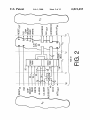
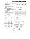
FIG. 2 is a simpli?ed diagram illustrating the principal
components of a microprocessor unit in accordance With the
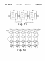
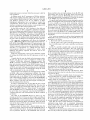
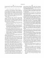
FIGS. 4 and 5 are diagrams illustrating MASTER and
SLAVE modes in accordance With the present invention.
upstream serial communication channel(s).
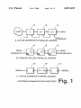
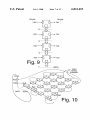
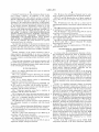
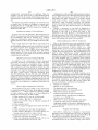
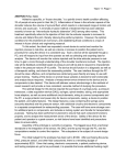
As representationally shoWn in FIG. 1 of the draWing,
upstream communication betWeen linked processing 10, 12
FIG. 1 is a diagram illustrating three types of upstream
present invention.
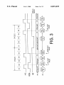
FIG. 3 is a timing diagram useful in understanding
operations of the present invention.
on Polling, that is, the “downstream” processor (remote
from the host) simply puts relevant information into a
speci?c location in memory, and the “upstream” processor
(nearer to the host) polls this location as appropriate. Active
means include “upstream interrupt” capability, and also
40
and 14 can be active or passive, With parallel or serial access.
Serial access is via UART, in Which the T><D line is
connected to the upstream device, While R><D is connected
to the doWnstream device. Parallel access is via a dual port
RAM as described in the above-referenced patent applica
tion.
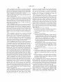
accordance With the present invention.
FIG. 7 illustrates operation across the I31 interface in
accordance With the present invention.
In FIG. 2 a simpli?ed schematic diagram is presented
disclosing the principal functional component of an
improved microprocessor unit (hereinafter referred to as an
“N/X-51 unit”) in accordance With the present invention.
The N/X-51 unit has tWo major subsystems S1 and S2, With
three major interfaces I1, I2 and I3, and a neW interface I3.
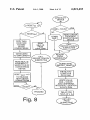
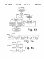
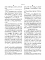
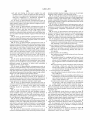
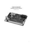
FIG. 8 depicts ?oW charts shoWing operational steps in
Subsystem S1 consists of a dual port RAM 20 as described
45
FIG. 6 illustrates a chain connection of 6 SLAVE units in
the last unit ID return methodology of the present invention.
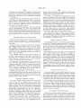
FIG. 9 is a simpli?ed diagram shoWing I/O channels
orthogonal to the main chain channel.
FIG. 10 illustrates an n-body of N/X-51 units spanned by
tWo orthogonal channels in accordance With the present
invention.
FIG. 11 is a diagram illustrating RAM space reservation
for accommodating up and doWn interrupt data transfers.
FIG. 12 illustrates array organiZation in accordance With
the present invention.
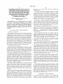
FIG. 13 is a How chart illustrating I/O port POLLing in
accordance With the present invention.
FIG. 14 is a block diagram illustrating orthogonal chan
nels originating and terminating at the host.
FIG. 15 illustrates the use of an array of N/X-51 units to
implement multiple orthogonal channels.
in the copending Klingman application. Subsystem S2 con
sists of a CPU 22 capable of executing instructions obtained
from S1, and the illustrated embodiment is of Harvard X-51
architecture referred to herein generally as an X-51 CPU.
55
Interface I1 describes the external address, data, and control
properties that, in the embodiment disclosed in the above
referenced application, connect subsystem S1 to a host, or
“upstream” subsystem SO. HoWever, in this embodiment an
additional interface I31 is also included as Will be explained
60
beloW. Interface I2 describes the internal address, data, and
control busses/properties that connect the dual port RAM
memory subsystem S1 to the CPU 22 (subsystem S2).
Interface I3 describes the external address, data, and control
busses that connect the CPU subsystem S2 to a “doWn
65
stream” device, subsystem S3.
In FIG. 2 the PnP component and the CODE ROM
components disclosed in the above-referenced application
6,021,453
5
6
are ignored for simplicity. It Will be appreciated that the host
supplies 16-bit Wide addresses to shared RAM and performs
identical unit can effectively be operated as a peripheral,
eight-bit data access to shared RAM. The local processor 22
also accesses byte-Wide data via 16-bit addresses. As shoWn,
thereby extending the architecture in a novel fashion, and,
With other features, to be described later, enabling a signi?
cant set of neW behaviors With potentially great utility. A
coincident Writes to the same location are resolved in favor
goal is to present a sixteen bit address to the dual port RAM
of the host. The X-51 architecture does not support Wait
states, therefore softWare should avoid simultaneous Writes
to the same location in shared RAM, via semaphores if
necessary.
The dual port shared RAM architecture S1 uses tWo bytes
of memory as interrupt subsystems, Which generate inter
subsystem S1 regardless of Whether the EISA or the uC
interface is selected. The EISA sixteen bit address is equiva
lent to a high eight bit address bus and a loW eight bit address
bus, When the most signi?cant address bits appear on the
high address bus and the least signi?cant address bits on the
loW address bus.
In accordance With the present invention, additional inter
rupts to the “opposite” side When Written to by either side,
and clears the interrupts When read by the “opposite” side.
This mechanism is ideal for the upstream interrupt con?gu
ration shoWn in FIG. 1a, and also performs doWnstream
interrupts as Well. The meaning of the interrupt is coded in
the actual byte Written to the interrupting location.
The host can read any byte in shared RAM independently
of the state of the local processor. This provides the passive
poll’ed method of upstream communication. The local pro
10
face I31 including latch circuitry 38 is added, capable of
selectively altering interface I1 to force interface I1 into
15
be selected.
20
cessor can Write an appropriate value to a particular location
at any time. The host can read this value by polling the
particular location and can interpret the value as appropriate.
Details disclosed in the copending Klingman patent hav
ing to do With the X-51 CPU architecture, Which are optional
for purposes of this invention are suppressed in FIG. 2 for
25
The neW interface, I31 is congruent With both I3 and I1. If
the I1 input mode is selected (ALE/Select=0) then the eight
bit latch 38 outputs 1s onto the loW address bus 31, Which
are overridden by the eight least signi?cant address bits
applied to the loW address bus input. (There are several
equivalent Ways to achieve this functionality using tri-state
latch outputs, etc.)
simplicity, and emphasis is placed on address, data, and
If the I3 congruent interface is selected, then the loW
address bus pins are unused, and they Will electrically “?oat”
interrupt bus details. Details relating to the address com
parator and WAIT signal to the host, as Well as the CODE
ROM are also not illustrated herein.
congruence With interface I3. An additional signal, the
EISA/uC* (ALE-in) signal input at 40 Will select the mode
of the upstream interface I1. If EISA/uC is loW, the EISA
mode of operation Will be selected. If high, the uC mode Will
30
high (via pullup resisters). The ALE signal from the I3
interface latches the contents of the data bus onto the loW
The external (upstream) interface I1 is chosen to be an
address bus, thereby overriding the unused pins and forcing
(E)ISA interface, for compatibility With the hundred million
the least signi?cant address bits onto the loW address bus.
The address is latched on the falling edge of ALE as shoWn
or so IBM PC clones in the market.
The external (doWnstream) interface I3 is chosen to be the
Intel 8051 microcomputer (uC) interface, probably the most
35
in FIG. 3, then the data appears on the data bus. FIG. 3 is a
timing diagram shoWing bus cycles in Intel 8051 Devices
executing from External Prog Memory and is taken from
common interface for peripheral devices such as the
Siemens 2085 ISDN Subscriber Access Circuit. The inter
Intel’s “MCS-51 Microcontroller Family User’s Manual”
face I3 is described in the Intel 8051 Design Manual.
page 1—19, February 1994.
The internal interface I2 may be generally described as a
16 bit address bus, an eight bit data bus, and a control bus
40
FIGS. 4 and 5 illustrate both N/X-51 unit modes: MAS
TER and SLAVE. It can be seen that either the MASTER is
consisting of CODE/DATA* RAM select, Read and Write
strobes (not shoWn), all of Which are applied to the dual port
RAM, and an interrupt signal from the dual port RAM. The
the only N/X-51 unit in a system, or it is the “most
upstream” N/X-51 unit. Since an N/X-51 unit in the SLAVE
mode looks like a peripheral device and each N/X-51 unit
details of the address and data busses are not as signi?cant, 45 can drive a peripheral device, then each SLAVE N/X-51 can
control a next SLAVE N/X-51, and this con?guration can be
repeated inde?nitely. Thus a means has been established of
inde?nitely extending a chain of SLAVE processors, With no
since they are internal and may be implementation speci?c.
The above description generally summariZes the doWn
loadable memory organiZation described by the referenced
Klingman patent, although the “shadoW ROM”, the RAM*/
inherent limit to the length of the chain. An example of such
a chain of six SLAVE units is depicted in FIG. 6.
ROM select line, or the behavior While reset, and any
ISDN-related features are not discussed. Other signi?cant
Each dual port RAM subsystem S1 is capable of produc
signals, speci?cally Reset, and Chip Select (CS), Will be
discussed later.
Of particular interest is a subset of the EISA bus, con
sisting of a 16-bit address bus 30, an eight bit data bus 32,
ing both an “upstream interrupt” to the host or an upstream
N/X-51 unit and a “doWnstream interrupt” from the host or
an upstream N/X-51 unit to the “current” X-51 subsystem
55
read and Write strobes 33, 34, all applied to the dual port
RAM subsystem S1, and an interrupt signal applied on line
36 from S1 to the upstream subsystem (or host) SO. This
interface is to be made congruent With the i8051 uC bus
consisting of an eight bit address bus, an eight bit multi
60
plexed address and data bus, an ALE (address latch enable)
signal, Read and Write strobes, and an interrupt signal.
The system has a directionality, as indicated by the terms
upstream and doWnstream. Normally the I1 interface
receives addresses from the upstream device (the host) While
the I3 interface presents addresses to a doWnstream device
(the peripheral). If I1 can be made congruent to I3, then an
65
S2. Therefore, in a preferred implementation, an upstream
device interrupts a doWnstream device by Writing to locate
0><7FF, While a doWnstream device interrupts an upstream
device by Writing to location 0><7FE. This provides for
immediate interrupt based communications up and doWn the
chain of processors. This does not preclude either POLLed
or SERIAL communications upstream and doWnstream,
and, is compatible With both POLLed and SERIAL com
munications along or across the chain. The N/X-51 n-Body
Architecture includes the integration of a processor unit With
a dual port SRAM-based mailbox memory and appropriate
bus interfaces to the dual port SRAM, With appropriate
partitioning of memory subspaces and With external
6,021,453
7
8
(upstream) access to memory While the processor is held in
Reset condition does not imply release of any SLAVE unit
reset condition.
from Reset, and, in fact, all SLAVE units Will remain in
In Master mode, the IC possesses an ISA-bus interface
With separate address and data paths as the “left” interface
instruction speci?cally loWering the 1/0 line that is attached
Reset condition until the MASTER unit executes an I/O
to the RESET pin of the next doWnstream X-51.
To specify any further behavior some assumption must be
to the dual port RAM, While the “right” interface to the dual
port RAM is internal to the IC. In addition, an 8051
made concerning the code executed by the CPU of each unit.
multiplexed address/data bus is provided to control the
To noW consider one of the more interesting schemes,
“downstream” devices such as the Siemens 2186 ISDN
assume that an X-51 program has been Written to accom
interface component and sub-circuits, or any peripheral I/O
devices using the 8051 microcomputer bus.
10
In the Slave mode, the “left” interface to the dual port
RAM becomes an 8051 compatible multiplexed address/
the code causes the MASTER unit’s X-51 to copy the code
from it’s oWn code RAM to the CODE RAM of the next
data bus, utilizing only eight (8) lines of the sixteen (16) line
ISA address, and utiliZing an “upstream” ALE-in signal line.
If ALE-in loW, use ISA-bus: (16-address, 8-data) If ALE-in
is hi, use 8051-bus: (8-HiAddr, 8-LoAddr/data, ALE-in)
15
Where ALE is the Address-Latch-Enable signal that causes
the loW 8 bits of address to be latched off of the data bus.
The supported con?guration Will alloW the folloWing
chain: (386)--|ISA|--(Master)--|uC|--(Slave)-|uC|--(Slave)|uC|--(I/O) Where (386) represents a PC-type processor, and
(I/O) represents an I/O device such as the Siemens 2086, and
--|bus|-- represents a bus across a speci?c interface, The ISA
interface is represented as --|ISA|--and the 8051
microcomputer interface is represented as --|uC|--, While
(Master) and (Slave) represent the N/X-51 unit in it’s
respective modes.
Either bus, the ISA bus or the uC bus, should be capable
of Writing into RAM While the 8051-processor is held in
reset.
reset.
25
30
35
multiple N/X-51 units are connected as a chain as depicted
1/0 line used to hold unit K+1 in Reset.
When unit #K+1 is released from Reset, it begins execut
ing the code that Was doWnloaded by unit #K. Since the code
is an exact copy of that in unit #K, and since unit K and K+1
are assumed to be identical, then unit #K+1 Will copy the
contents of it’s oWn code RAM into the code RAM of unit
#K+2, then release unit #K+2 from Reset.
40
This scenario is the simplest, but, With appropriate CODE
From the above it can be seen that: if K, then K+1. Since
it is knoWn that this is true for some K=1, then, by induction,
in ROM, offers novel computational abilities. The more
it is true for all K.
general case assumes the presence of a host processor that
doWnloads code to the Master N/X-51 unit (#1) While the
unit is held in Reset condition, and causes the ROM/RAM*
code, and then released from Reset. The code causes the
address presented to the I31 interface to access CODE RAM
of the K+1st device, and the data bus is used to copy the code
at the corresponding address in device K’s code RAM into
the code RAM of device #K+1.
Assume that the code executed by unit K causes an exact
copy of itself to be loaded into unit K+1 before releasing
device #K+1 from Reset condition by loWering the speci?c
“shadoW” ROM (See referenced Klingman patent). The
in FIG. 6, each unit Will begin executing its oWn code ROM
When released from reset. Communication along the chain
Will be determined by the code in ROM.
doWnstream unit before releasing the next doWnstream X-51
from Reset.
If “n” units are assumed to be in the chain, beginning With
MASTER unit #1 and terminating With SLAVE unit n, the
procedure is as folloWs:
1. Host loads unit #1 and releases reset.
2. Unit #1 copies “self” code to unit #2 and releases reset.
K+1. Unit #K copies “self” code to unit #K+1 and releases
In FIG. 7 a unit #K is loaded With a copy of the desired
Consider ?rst the case in Which no host processor exists.
In this case the X-51 code is assumed to reside in the
ROM is selected at startup via the ROM/RAM* selection
pin, and execution proceeds from ROM location Zero. If
plish the scheme. Assume that the host is used to doWnload
the program into the CODE RAM of the MASTER unit’s
X-51 While it is held in Reset condition. Assume further that
45
line to select CODE RAM When the unit is released from
Reset condition. The ?rst unit then begins executing the
Thus, an inde?nitely extensible chain of processors has
been provided, that is, a chain of indeterminate length.
This has obvious utility for modeling DNA and protein
chains, Which are exceedingly long.
Under very general conditions, a host such as an IBM PC
clone (Pentium, etc.) can load X-51 code across an EISA bus
into a MASTER N/X-51 unit While that MASTER unit and
all doWnstream SLAVE units are held in Reset. Upon release
code doWnloaded from the host.
In order to extend this case, We note that the X-51 of unit
1 is reset by a high signal on the RESET line. Note also that
all X-51 I/O lines are forced high When the X-51 is reset.
from Reset, the MASTER unit’s CPU simply copies it’s oWn
Thus, if the RESET lines are “daisy chained” by specifying
code to the next doWn stream SLAVE unit and releases the
that the RESET line of a “downstream” X-51 is controlled
by an 1/0 line of an “upstream” unit, then the MASTER or
“farthest upstream” unit Will determine the Reset condition
SLAVE unit from Reset. After this minimal function, the
X-51 code is generally unrestricted, and can communicate
via it’s oWn dual port RAM With the host (or next upstream
device) or via the dual port RAM of the next doWnstream
55
as folloWs.
The CPU of the MASTER N/X-51 is reset ( by any
means) and all of it’s I/O lines are driven high. According to
the assumption, one of these I/O lines is connected to the
RESET pin of the next doWnstream X-51, and each unit Will
therefore be forced into Reset, ad in?nitum. Thus, the initial
state of the chain of N/X-51 units is completely determined,
regardless of the length of the chain.
Having placed the chain into a knoWn initial state, the
question is raised, What occurs When the MASTER N/X-51
unit is released from Reset. In general, only the folloWing
can be predicted: Release of the MASTER unit from the
unit. Thus, except for the above speci?ed startup behavior,
the X-51 code is completely unspeci?ed and therefore can
be considered general purpose enough to represent any
60
system described or approximated via a linear chain.
Note that the above system functions as described for
inde?nitely long chains, and is completely independent
(except for initial “per copy” propagation delays) of the
65
actual length of the chain. In fact, no knoWledge of the
length exists at this point.
While this is a poWerful feature (obviously more poWerful
than if it only Worked for speci?c lengths) it can be assumed
6,021,453
10
buffered interrupt based RS-232 port With transmit and
that there are applications in Which, at a minimum, each
device Would need a unique identi?er for any communica
receive lines. Features such as adaptive baud rate, transmit
and receive queues, Clear-To-Send (CTS) and Data Termi
tion along the chain other than nearest neighbor communi
cations.
Amethod must therefore be devised by Which each device
can establish it’s oWn ID and also identify the length of the
processor chain.
As before, assume that the host loads the CODE RAM of
unit #1 and then releases unit #1 from reset. Assume further
the host Writes the number “1” into a speci?ed location in
unit #1’s DATA RAM. Assume further that initialiZation
code executed by unit #1 not only copies it’s oWn CODE
RAM to the CODE RAM of unit #2, but also reads the
contents of it’s speci?c DATA RAM, increments the value
by one, and then Writes the incremented value into the
corresponding location in unit #2’s DATA RAM.
nal Ready (DTR), etc., can be implemented via program
ming.
Referring noW to FIG. 9, an illustration is provided
shoWing that serial I/O channels in a string of N/X-51 units
can be considered completely orthogonal to the “main chain
channel”.
For simplicity, the preferred implementation has one
transmit line T><D, and one receive line R><D, and an
15
is available for the next message unit to send. Typical usage
of such facilities involves load or unloading the relevant
In this fashion it can be seen that the initialiZation
procedure both propagates the common code and counts the
number of N/X-51 units in the chain, assigning each unit a
unique ID equal to it’s sequence number in the chain.
While this provides an ID for each unit in the chain, it
buffer in real time, during the execution of the interrupt
service routine, then setting a “?ag” or special bit to record
the action, then returning from the interrupt. Only the
message buffers and the ?ags Will have changed, due to the
does not provide each unit With knoWledge of the length of
the chain.
For the folloWing, assume a particular I/ O pin or other pin
is tested at each device. Obvious pins are the doWnstream
RESET output line or the upstream interrupt input as Will be
interrupt. If these resources are set aside for use by T><D and
25
R><D, then the interrupt is invisible to the interrupted pro
gram and therefore effectively orthogonal to said program.
Of course in practical applications one may not Wish for
complete decoupling betWeen the different channels. Instead
seen, hoWever any general purpose I/O pin Will do.
In the simplest case, simply tie the RESET pin of the last
processor in the chain to ground. (Note: the units are
assumed not to knoW hoW long the chain is. We, hoWever,
are assumed to knoW the length of the chain, and if not, then
the channels may be vieWed as existing in different “planes”
or “spaces”. In fact, in the preferred implementation, the
channels may be assumed to operate on different “scales”.
Such an implementation is described beloW.
We are at least assumed to knoW Which is the last device, that
The Folding Problem in a Chain
is, Where the end of the chain is.)
The pin test routine is illustrated by the How charts in FIG.
8 Which are believed to be self-explanatory. Suffice it to say
that as the last unit n is reset and its RESET out line is tested,
the detected ground state Will cause the unit to read its ID
from its data RAM and Write such ID into a speci?ed
interrupt associated With each. The R><D interrupt indicates
a message unit (typically 7—8 bits) has been received (With
proper framing, etc.) and is available in the R><D buffer. The
T><D interrupt indicates that the transmit buffer is empty, and
35
Because the N/X-51 unit architecture strongly supports a
chain of processors, it is designed to tackle problems Which
have chain topology in the real World; such as DNA and
protein folding for example. In these polymer chains most
forces are nearest neighbor, that is, any particular element
normally depends most strongly on the nearest upstream
location of the upstream data RAM, then interrupt the
upstream unit. This Will cause the upstream unit to itself read
the ID stored in its data RAM and Write it into the speci?ed
location in the next upstream unit’s data RAM, etc. This
operation Will continue until the ID of the last unit in the
element and the nearest doWnstream element. The inherent
scale of the problem is basically a function of the average
chain has been handed all the Way back along the string of
nearest neighbor distances. HoWever, because the elements
are not rigidly coupled, but alloW some variation in angles,
each particular couple may deviate someWhat from the
units to the MASTER unit Which Will then report same to the 45
direction established by the complementary couple.
host. It Will thus be appreciated that in accordance With the
present invention a data processing unit has been provided
It is this deviation that, over a number of elements, leads
to folding, and, in fact, it is the folding, or tertiary structure
of proteins and DNA that generally underlie the important
(biological) behavior of the system.
that can be connected in series With a multiplicity of like
units, and the resulting string of units Will be able to perform
a series of identical or other predetermined operations in a
Such folding is complex, and generally unpredictable, and
serial sequence. The string Will also be capable of deter
mining and reporting back to the host the length of the string.
provides the major reason for interest in computations that
may be achieved With an N/X-51 unit chain.
Orthogonal Communication Channels
The N/X-51 units can also contain orthogonal communi
cation channels. For example, the basic communication
channel uses shared RAM With interrupt signaling up and
55
doWn the chain. This may be vieWed as a communication
channel connecting the elements in the chain With direct
connection to nearest neighbor elements, and cooperative
connection to remote elements of the chain (via the coop
eration of intervening elements in the chain). HoWever,
alternate “orthogonal” channels may also be achieved via
other 1/0 or communication subsystems.
The X-51 possesses one or more bit serial communication 65
channels based on the Widely used RS-232 protocols or 12C
protocols or both. The X-51 RS-232 port is a simple double
From the perspective of a nearest neighbor model chain,
the major consequence of folding is that elements Which are
initially distant from one another, and therefore independent
of each other, may, through folding of the chain, be brought
into close proximity, that is, into each others near neighbor
hood.
The problem is hoW to detect this proximity. There is no
knoWn general solution. This invention utiliZes orthogonal
channel(s) to provide a solution as depicted in FIG. 10 Which
shoWs an n-body array (4x5) of N/X-51 units spanned by
tWo orthogonal channels.
The n-body array of tWenty N/X-51 units is connected in
a linear chain topology, that is, unit 1 is connected to unit 2
Which is connected to unit 3, and so forth until unit 19 is
6,021,453
11
12
connected to unit 20, all via the “main chain channel”
reserved by device K+1 for this operation. Then device K
Will Write the unique N-doWn command byte into the
doWnstream interrupt location in K+1’s data RAM. This Will
consisting of shared dual port RAM plus bidirectional
interrupts. In this implementation, the host communicates
via the EISA bus interface With unit #1, the MASTER unit,
cause device K+1 to be interrupted. K+1 Will read the
Which communicates With SLAVE unit #2, Which commu
nicates With SLAVE unit #3, etc. The establishment of this
interrupt location, thereby clearing the interrupt and retriev
chain is as described previously using the “doWnload While
reset” and self ID enumeration and propagation procedures.
to mean that neW N-doWn data exists in its reserved block.
This completes the doWnstream transfer. K+1 can noW
The doWnloaded program can initially compute its oWn
position in the chain based on its self-ID and upon an initial
ing the N-doWn command. K+1 then interprets the command
10
element-to-element distance. Thus each element can com
pare its “position” With that of its nearest neighbors, and
determine What next step to take, based on Whatever inter
began the procedure.
action betWeen neighbors is assumed. Keep in mind that
“position” need not necessarily be actual physical position
15
of the unit, and may in fact be any assigned position.
Moreover, the characteristic of inherent need not be position,
it could be any other variable, such as temperature or
pressure, etc. After each such action, there may be a change
in an element’s position (either absolutely or relative to its
neighbor, or both) and thus a neW interaction must be
computed and responded to. In this fashion each element of
the chain evolves in response to its nearest neighbors, and,
NoW the upstream direction. Again, assume that K has
received an N-up message from K+1. Device K Will handle
this message, as appropriate, and Will also pass the message
upstream to device K-1. Device K Will simply Write the
N-up command byte into K’s upstream interrupt location,
thereby generating an upstream interrupt to device K-1.
Device K-l Will read the upstream interrupt location
(thereby clearing the upstream interrupt signal) and interpret
the N-up command byte to mean that Device K’s N-up block
through these, more distant neighbors. Thus for example,
“displacement” of one element may ?rst affect only its
access the data, handle it as appropriate, and then copy it into
K+2’s N-doWn block of RAM and then interrupt device
K+2. This continues until the message reaches the doWn
stream end of the chain. In this fashion every doWnstream
device Will receive the position of the upstream device that
of RAM holds data. Since device K-l has direct access to
25
(doWnstream) device K, then K-l Will read the data from
nally displaced element.
K’s dual port RAM and copy it into its oWn N-up block of
RAM. This completes the upstream transfer. Device K-l
Will then handle the data appropriately, and then Will inter
rupt device K-2 With an N-up command. In this Way the
N-up Will be transferred upstream until it reaches the
upstream end of the chain.
Thus, if every element in the chain periodically sends its
What happens if, after the machine has run for some time,
the folding in 3-dimensional space has brought the initially
displaced element and the remote element (for example) into
close proximity? In the real World, close means strongly
doWnstream, then every element in the chain Will receive
every other elements position on a periodic basis. Note that
semaphores or other techniques may be required to prevent
nearest neighbor, Which may move in response to the
displacement. This move Will be detected by its nearest
neighbor, Which may then respond, and in this Way, changes
to one element may be felt by remote elements (after a
propagation delay) even though there is never any direct
communication betWeen the remote element and the origi
oWn position (N-ID=self-ID) both upstream and
35
collisions, but such methods are Well knoWn to one skilled
in the art.
interacting, yet our model sees only Weak interaction as
described above, if it sees any interaction at all! (With ?nite
resolution, We have, in effect, a noise level, or threshold
beyond Which changes Will not propagate.) This is a real
problem for linear chain models.
The present invention alloWs various approaches to this
problem, of Which only tWo are mentioned herein.
First, each element may be responsible for keeping track
of the locations of all other elements in the chain, and
thereby determining When any other element has moved into
Thus, each element can be responsible for keeping track
of the locations of all other elements in the chain, With the
goal of determining When any other element has moved into
the ?rst element’s neighborhood.
As described above, upon receipt of the N-position
message, a device should “handle” the message. In general
45
there are tWo Ways to handle the message. Either the
receiving element determines the N-ID of the incoming
message, and copies all of the position information into the
appropriate “N-slot” in an array of positions, for later
analysis, or the receiving element immediately compares the
incoming position to the element’s oWn position, and deter
its neighborhood. An example algorithm to accomplish this
might be:
Periodically (via timer interrupt, count background loops,
etc.) transmit ones oWn address both upstream and
mines at once Whether or not the incoming position indicates
doWnstream, using interrupts. For example, assume that the
“N-command” has the folloWing format:
that another element has moved into the receiving element’s
neighborhood. If not, then the incoming message can be
discarded (after properly transmitting said message up or
doWnstream, as appropriate). If so, then the implication is
Nicommand NiID Xiposition Yiposition Ziposition time
55
Each N/X-51 unit Will reserve enough dual-port RAM
space for its neighbor upstream, and its neighbor doWn
that folding of the chain has brought element (N-ID) and the
receiving element into close proximity, and both of these
stream to transfer position messages to or from. FIG. 11
elements should begin interacting.
shoWs N-up and N-doWn: N-up is sent upstream, to loWer
numbered devices, While N-doWn ?oWs doWnstream to
This completes the ?rst method of detecting folding in a
chain, and determining Which elements become neighbors as
higher numbered devices:
a consequence of the folding. There are disadvantages to this
To illustrate, assume K has received an N-doWn message
method hoWever. For practical purposes, the longer the
from K-l. K Will handle this message (as Will be seen later)
and Will also pass the message doWnstream to K+1. This is
accomplished as folloWs: Device K, Which has direct access
to the dual port RAM belonging to its doWnstream neighbor
Will ?rst copy the message into the N-doWn block of RAM
chain, the more utility one Will expect from the system, as
all real proteins tend to be very long indeed. This has several
65
undesirable aspects. First, the length of the message (in bits
or bytes) must groW merely to keep track of positions in a
very long chain. For example, relative position in a 100
6,021,453
13
14
chain can be recorded in one byte, Whereas at least three
be used as previously described to transfer every element’s
bytes are needed in a 100,000-chain. Second, if the position
position upstream and doWnstream to all other elements.
Instead, the problem Will be approached from a system
perspective. For example, the host (assumed to be a Pentium
of each element is recorded in an array in dual port RAM the
array Will get very long. While at the time of application,
Toshiba is discussing 256M bit RAM plus logic on a single
chip, this solution is not yet available, and the initial X-51
has only 16 K-bits of data RAM. Third, increasing amounts
of time (proportional to N) are required simply for message
passing, thereby diminishing the time each element can
spend dealing With its current nearest neighbors.
Thus, the problem of folding in a chain has been solved,
or better) can send a request to each element via the RS-232
(bit serial) channel. The designated element Will respond by
transmitting its n-position message “doWn” the RS-232
chain until it reaches the host. All other elements simply pass
10
the message along, With no storage or analysis. Unlike the
“main chain channel” Which is bi-directional, a single bit
serial channel is uni-directional—all ?oWs are “doWn
stream”.
but the solution has a number of draWbacks. NoW consider
the second, preferred, implementation designed to solve the
HoW does this approach to the folding problem differ?
First, With the exception of recogniZing When a command
folding problem in a chain. Recall the tWenty N/X-51 units
connected in a chain topology. From FIG. 10 it can be seen 15 is for a device itself, all analysis is moved to the host. That
that the “main chain channel” connects units 1-2-3-4-. . .
is, devices no longer must compare their oWn position to all
others. The host noW does the comparison. This has numer
ous consequences. The host (a Pentium) is much more
-17-18-19-20, thereby yielding a linear-chain, While the
actual N/X-51 chain is folded several times, to yield four
roWs of ?ve N/X-51 units. This folding of the devices occurs
simply to ?t more devices on a printed circuit board, and has
no relation to the folding of the computational model chain
that Will be built using the physical chain of N/X-51 units.
This point should be understood before proceeding. That is,
even through the physical chain of N/X-51 processing units
is folded, the connected chain has a linear topology, and the
initialiZation procedure described earlier Will distribute the
computational model chain along a line beginning at posi
poWerful than the X-51 (an 8051 equivalent poWer device)
and it is expected that this Will alWays be the case. That is,
ten or tWenty years from noW, the X-51-type device Will be
vastly more poWerful, but We expect that the host processor
Will have improved proportionately.
25
tions. The host, hoWever, is faster and smarter, With more
available data memory, and can be expected to apply more
intelligent analysis. For example, the host may use a grosser
tion (self-ID=1) and extending to position (self-ID=20) in
model-space.
With this understood, consider a second, orthogonal com
scale, dividing the problem into larger regions of space, and
ignoring elements that fall in (or out of) certain regions.
munications chain, based on the RS-232 bit serial commu
nications channel. Note that one could tie the host T><D to
the Master N/X-51 unit #1’s R><D, then tie unit #1’s T><D to
unit #2’s R><D, unit #2’s T><D to unit #3’s R><D, and so forth,
providing a communication channel that topologically “par
allels” the “main chain channel” described above. Instead, to
Thus, for example, if X-51 s are keeping track of folding,
We expect them to do so at the maximum resolution, that is,
at the same resolution used for nearest neighbor computa
Similarly, the host may do more predictive analysis,
measuring velocities, and using projected paths for closer
35
observation. That is, based on current positions and
velocities, the host may decide that some segments of the
emphasiZe the complete orthogonality of the tWo channels,
proteins (say) require more frequent attention, and other
We tie unit #1’s T><D to unit #10’s R><D, thence unit #10’s
T><D to unit #11’s R><D, unit #11’s T><D to unit #20’s R><D,
Which then loops back from unit #20’s T><D to unit #19’s
R><D, unit #19’s T><D to unit #12’s R><D, unit #12’s T><D to
This supports the earlier statement that orthogonal channels
segments can be checked less frequently, thereby optimiZing
in some sense the use of the RS-232 (or bit serial) channel.
may even represent different scales.
In this sense also note that grosser time scales are appro
unit #9’s R><D and so on. While in a sentence, this appears
non-sensical, We observe from FIG. 12 that We are simply
running our RS-232 channel up and doWn columns in the 4
roW by 5 col N/X-51 unit matrix in Which the “main chain
channel” is looped back and forth along roWs. Of course, if
45
priate to grosser position scales. In general the motion of a
segment of protein is much sloWer than the motion of its
constituent elements, therefore the use of the (generally)
sloWer bit serial channel instead of the faster “main chain
channel” is not a disadvantage, but is actually a more
one lengthened either the roWs or the columns, the “main
appropriate mapping of resources according to the charac
chain” could be kept connected linearly from the ?rst to the
last, but all of the RS-232 connections Would be re-ordered,
assuming that the same column based looping for RS-232 is
retained. The looping behavior is easy to draW, and can be
seen to provide “nearest neighbor” connections in physical
teristics of the physical problem being modeled.
Even so, the same problem of very long chains is present
With the bit serial channel solution to the folding problem.
There are tWo primary approaches to this problem. First, as
space, thereby minimizing (and simplifying) the physical
interconnections, either metalically via printed Wiring
indicated above, the host can use more predictive analysis to
assemblies or optically. The looping clearly spans the N/X
51 unit space; that is, all N/X-51 units Will be connected in
55 optimiZing use of the channel. Second, one can throW more
this fashion, With none left out. Finally, the “last” unit on the
RS-232 corn port, the host may employ an Octal UART of
focus communication Where it is most appropriate, thereby
hardWare at the problem. For example, instead of a single
RS-232 (or other bit serial) channel has an uncommitted
the kind available from Cybernetic Micro Systems, Inc., as
output port, T><D. This conveniently ties into the (unused)
R><D port of the host processor, thereby closing the loop.
NoW to investigate possible applications of this loop.
Well as other manufacturers, such as Quatech.
To illustrate this solution on the same 4 roW by 5 col
matrix of N/X-51 units, using the eight port Octal UART at
the host, one possible topology is shoWn in FIG. 12:
The Folding Problem With Orthogonal Channels
Returning noW to the folding problem, assume the N/X
51 units represent the amino acid building blocks of pro
teins. The “main chain channel” Will perform nearest neigh
bor communications and interactions as before, but Will not
In this ?gure, ?ve bit serial loops reduce the longest loop
65
transit to one ?fth of the original transit. That is, Where
originally a message had to How through tWenty processors
before the host received a response, noW the host receives
the response after only four processor delays. (For clarity,