1
Table of Contents
Preface
Who Should Use this Manual ............................................................... P–1
Purpose of this Manual ........................................................................ P–1
Contents of this Manual ....................................................................... P–1
Where to Find Help.............................................................................. P–2
Using the Manual Set .................................................................... P–2
Using Online Help.......................................................................... P–3
Related Documentation........................................................................ P–4
Rockwell Automation Support .............................................................. P–4
Local Product Support ................................................................... P–4
Technical Product Assistance ........................................................ P–5
Common Techniques Used in this Manual ........................................... P–5
GML Ultra Overview
Chapter 1
How it Works ....................................................................................... 1–1
Motion Controllers that Use GML Ultra................................................. 1–1
Personality Module for ULTRA Plus Controllers ................................... 1–2
Communications for ULTRA Plus Controllers....................................... 1–2
RS-232 .......................................................................................... 1–2
RS-422 .......................................................................................... 1–2
Multi-drop mode ............................................................................ 1–2
Before you Begin
Chapter 2
Understanding Your Work Area............................................................ 2–1
GML Ultra Application Window ...................................................... 2–1
GML Ultra Diagram Window .......................................................... 2–2
Diagram Editor Window................................................................. 2–2
Online Manager Window ............................................................... 2–3
Trace Window ............................................................................... 2–5
Watch Window .............................................................................. 2–6
Command Window ........................................................................ 2–7
Script Editor Window ..................................................................... 2–7
Quick Reference to GML Ultra Windows........................................ 2–8
Understanding Your Tools.................................................................... 2–9
Title Bar......................................................................................... 2–9
Main Menu..................................................................................... 2–9
Block Palettes and Libraries........................................................... 2–9
Color Code for Blocks.................................................................. 2–11
General Procedures
Chapter 3
Starting GML Ultra ............................................................................... 3–1
Creating New Files............................................................................... 3–1
Creating a New Diagram................................................................ 3–1
Creating a New Script.................................................................... 3–3
Publication 1398-5.11 - February 1997
ii
Table of Contents
Opening Existing Files..........................................................................3–4
Opening a Diagram ........................................................................3–4
Opening a Script ............................................................................3–5
Editing GML Ultra Files.........................................................................3–6
Making Changes to Your Diagram ..................................................3–7
Editing Your Script .......................................................................3–10
Saving and Naming a New File...........................................................3–10
Saving and Naming a New Diagram.............................................3–11
Saving Changes to a Diagram......................................................3–11
Changing a Diagram’s Name and Location...................................3–11
Naming a Block ..................................................................................3–11
Naming a Module ...............................................................................3–12
Printing Files ......................................................................................3–12
Setting Up Your Printer.................................................................3–13
Printing a Diagram .......................................................................3–13
Printing a Script............................................................................3–15
Closing a File......................................................................................3–15
Closing a File Before Saving It .....................................................3–16
Closing a File Already Saved and Named ....................................3–17
Exiting GML Ultra ...............................................................................3–17
Working With Blocks
Chapter 4
Selecting and Positioning Blocks on the Diagram Editor Window..........4–1
Using the Diagram Library ..............................................................4–1
Using the Block Palette ..................................................................4–2
Manipulating Blocks..............................................................................4–3
Using the Cursor.............................................................................4–3
Connecting Blocks..........................................................................4–3
Moving Blocks................................................................................4–4
Showing the Connection Lines........................................................4–4
Disconnecting Blocks .....................................................................4–4
Making Changes to Your Diagram ........................................................4–5
Selecting All ...................................................................................4–5
Duplicating a Block.........................................................................4–5
Adding a Block ...............................................................................4–5
Replacing a Block...........................................................................4–6
Inserting a Block.............................................................................4–6
Grouping Blocks .............................................................................4–6
Swapping Blocks ............................................................................4–7
Aligning Blocks...............................................................................4–8
Spacing Blocks...............................................................................4–9
Snapping to the Grid.............................................................................4–9
Accessing Block Information...............................................................4–10
Setting Block Function Parameters.....................................................4–10
Using Mathematical Expressions as Values ........................................4–11
Understanding Expressions ..........................................................4–11
Using the Expression Builder........................................................4–12
Building an Expression .................................................................4–13
Using Variables, Constants, and I/O User Variables .....................4–14
Publication 1398-5.11 - February 1997
Table of Contents
Working with
Diagrams
iii
Chapter 5
Creating New Diagrams ....................................................................... 5–1
Editing Your Diagram as you Build It.................................................... 5–1
Working with Finished Diagrams.......................................................... 5–2
Accessing the Diagram Menu ........................................................ 5–2
Finding a Specific Block or Parameter ........................................... 5–2
Finding the Same Block or Parameter Again ................................. 5–3
Diagram Information...................................................................... 5–3
Testing Diagrams................................................................................. 5–4
Accessing the Online Manager............................................................ 5–5
Inserting a Breakpoint .......................................................................... 5–5
Documenting Your Diagram................................................................. 5–5
Accessing Previous Documentation............................................... 5–6
Using Preexisting Modules to Create Diagrams.................................... 5–7
Using a Preexisting Module ........................................................... 5–7
Using a Preexisting Diagram ......................................................... 5–8
Converting a Diagram to a Script ....................................................... 5–10
Working With Modules
Chapter 6
Creating a New Module........................................................................ 6–1
Using the Block Palette.................................................................. 6–1
Using the Diagram Library ............................................................. 6–2
Using the Edit Menu ...................................................................... 6–2
Encapsulating Blocks or Modules................................................... 6–3
Using an Existing Module..................................................................... 6–4
Unencapsulating a Module................................................................... 6–5
Viewing Modules.................................................................................. 6–6
Viewing Module Details.................................................................. 6–6
Viewing a Module Overview .......................................................... 6–7
Displaying Module Information............................................................. 6–9
Documenting a Module ........................................................................ 6–9
Working with Scripts
Chapter 7
Translating a Diagram to Script............................................................ 7–1
Successful Translation to Script..................................................... 7–2
Handling Unsuccessful Translations............................................... 7–3
Creating a Script .................................................................................. 7–5
Editing a Script .................................................................................... 7–5
Using the Edit Menu Functions ...................................................... 7–5
Using the Script Menu Functions ................................................... 7–7
Printing Your Script.............................................................................. 7–9
Going Online
Chapter 8
Using the Online Manager Window ...................................................... 8–2
How the Window is Organized ....................................................... 8–3
Publication 1398-5.11 - February 1997
iv
Table of Contents
Choosing the Information View Mode....................................................8–4
Selecting a Communication Function....................................................8–4
Sending Commands Directly to an ULTRA Plus .............................8–4
Showing Watch Items.....................................................................8–5
Downloading Your Diagram ..................................................................8–6
Downloading Axis and Drive Setup Data ........................................8–6
Executing a Direct Motion Command....................................................8–7
Deleting a Diagram...............................................................................8–7
Controlling Online Functions.................................................................8–8
Functions for Managing Program Files ...........................................8–8
Functions for Managing Program Execution ...................................8–9
Starting and Stopping Programs .........................................................8–10
Starting a Downloaded Program ...................................................8–10
Pausing a Program.......................................................................8–10
Suspending a Program .................................................................8–11
Resuming a Suspended Program .................................................8–11
Stopping a Program .....................................................................8–11
Stopping a Program and Killing Motion.........................................8–11
Monitoring Program Flow....................................................................8–11
Using Trace..................................................................................8–12
Using Auto....................................................................................8–12
Using Step....................................................................................8–13
Setting a Breakpoint .....................................................................8–13
Defining Watch Items ...................................................................8–14
Monitoring Watch Items................................................................8–15
Examining Variable Values...........................................................8–15
Selecting Axis Setups Options ............................................................8–16
Viewing Version Information ...............................................................8–16
Initializing the Personality Modules .....................................................8–17
Selecting and Running Diagnostic Tests .............................................8–18
Testing the Encoder .....................................................................8–18
Testing the DAC Output ...............................................................8–19
Testing the Monitor Output ...........................................................8–20
Testing the Digital Outputs ...........................................................8–21
Testing the Operator Terminal......................................................8–22
Testing the Nonvolatile Memory ...................................................8–22
Tuning Motors and Drives...................................................................8–22
Understanding Auto Tune .............................................................8–22
Using Auto Tune...........................................................................8–23
Understanding Manual Tune.........................................................8–28
Using Manual Tune ......................................................................8–28
Monitoring I/O Status..........................................................................8–36
Upload Options...................................................................................8–37
Transferring a Script File ..............................................................8–37
Transferring a NVRam Image.......................................................8–38
Transferring the Fault History .......................................................8–38
Transferring an Executable File....................................................8–39
Publication 1398-5.11 - February 1997
Table of Contents
Understanding Blocks
v
Chapter 9
Change Gain ................................................................................. 9–1
Change Jog Dynamics................................................................... 9–3
Clear Display ................................................................................. 9–5
Define Scan Event......................................................................... 9–6
Define Xkey ................................................................................... 9–8
Delay............................................................................................. 9–9
Disable Gearing........................................................................... 9–10
Edit Value.................................................................................... 9–10
Equation ...................................................................................... 9–12
Feedback..................................................................................... 9–13
Fkey ............................................................................................ 9–14
Gear Axes ................................................................................... 9–15
If Axis .......................................................................................... 9–17
If Expression................................................................................ 9–19
If Fault ......................................................................................... 9–20
If Input ......................................................................................... 9–21
If Move ........................................................................................ 9–22
If Registration .............................................................................. 9–23
If Timeout .................................................................................... 9–24
Jog Axis....................................................................................... 9–26
Motion Settings............................................................................ 9–27
Move Axis ................................................................................... 9–28
New Module................................................................................. 9–29
Output On.................................................................................... 9–30
Output Off ................................................................................... 9–31
Patch Statement.......................................................................... 9–32
Pause Move ................................................................................ 9–33
Print Fault.................................................................................... 9–33
Print to Display ............................................................................ 9–34
Redefine Position ........................................................................ 9–35
Registration ................................................................................. 9–36
Reset Axis Fault .......................................................................... 9–37
Reset Drive ................................................................................. 9–38
Resume Move ............................................................................. 9–38
Scan Event Handler..................................................................... 9–38
Set Condition............................................................................... 9–39
Set Scan Timer............................................................................ 9–41
Slew Disable................................................................................ 9–42
Slew Enable ................................................................................ 9–42
Stop Motion ................................................................................. 9–43
Terminal Monitor ......................................................................... 9–44
Wait For Axis............................................................................... 9–45
Wait For ENTER ......................................................................... 9–46
Wait For Expression .................................................................... 9–46
Wait For Input On........................................................................ 9–47
Wait For Input Off........................................................................ 9–48
Wait For Registration................................................................... 9–49
Xkey ............................................................................................ 9–50
Xkey Handler ............................................................................... 9–51
Publication 1398-5.11 - February 1997
vi
Table of Contents
Publication 1398-5.11 - February 1997
Preface
Preface
Read this preface to familiar yourself with this manual. This preface
covers the following topics.
l
Who should use this manual
l
The purpose of this manual
l
The contents of this manual
l
Related documentation
l
Where to find help
l
Technical support
l
Common techniques used in this manual
Who Should Use this Manual
Use this manual if you are responsible for designing, testing, or
debugging GML Ultra® diagram programs used with
ULTRA Plus® controllers. GML Ultra is a member of the GML™
family.
Purpose of this Manual
This manual is a user guide for the GML Ultra programming tool. It
describes the procedures you use to design a diagram; define the
parameters of each block function; and download, test, and debug the
diagram, all using the graphical interface unique to GML.
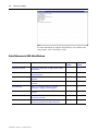
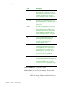
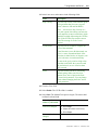
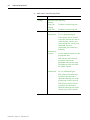
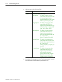
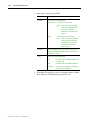
Contents of this Manual
Chapter
Title
Contents
1
Overview of
GML Ultra
This chapter provides an introduction to
GML Ultra.
2
Before You
Begin
This chapter describes what you need to
know about GML Ultra before you build
your first diagram. It includes:
Descriptions of the GML Ultra screen;
what it looks like, how it works, what
options are available to make your
diagram easy to build, easy to copy,
easy to find, and easy to troubleshoot.
Descriptions of GML Ultra menus and
toolbars.
Descriptions of function block libraries.
Publication 1398-5.11 - February 1997
P-2
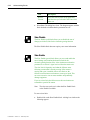
Preface
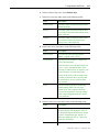
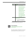
Chapter
Title
Contents
3
General
Procedures
This chapter contains step-by-step
procedures you use to create and edit
diagrams and scripts.
4
Working with
Blocks
This chapter covers the physical aspect
of blocks, such as selecting, moving,
and using blocks to define functions for
your diagram. It also describes how to
use the Expression Builder feature.
5
Working with
Diagrams
This chapter provides procedures for
creating, testing, and documenting your
diagram.
6
Working with
Modules
This chapter includes procedures for
creating, viewing, and documenting
modules.
7
Working with
Scripts
This chapter provides procedures for
using the Script Editor, translating a
diagram to script, and printing the script.
8
Going Online
This chapter includes procedures for
downloading a diagram, debugging and
fine tuning, and uploading controller
options.
9
Understanding
Blocks
This chapter gives a brief explanation of
each block’s function and directions for
using each block. For detailed
information about blocks, refer to the
GML Ultra Reference Manual.
Index
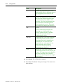
Where to Find Help
GML Ultra provides two types of help:
l
A set of user manuals.
l
Online help.
Using the Manual Set
This manual is part of a documentation set for GML Ultra:
l
GML Ultra Getting Started (publication 1398-5.10).
l
GML Ultra User Manual (publication 1398-5.11).
l
GML Ultra Reference Manual (publication 1398-5.12).
Publication 1398-5.11 - February 1997
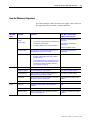
Where to Find Help
Use this
manual
GML Ultra
Getting Started
To find information on this topic
l
l
l
l
GML Ultra User
Manual
l
l
l
l
GML Ultra
Reference
Manual
P-3
l
l
l
Installing the software
Starting the software
Setting up the system
Connecting the hardware
Basic features and functions
Screen, menu, and toolbar functions
Mechanics of working with blocks, modules, and
diagrams
Basic block definitions
Setup details
Expression Builder details
Block function details
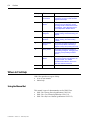
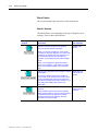
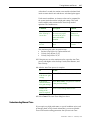
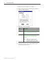
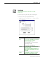
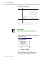
Using Online Help
You have access several types of online help:
To use this
Do this
Description
GML help
Select Help from
the menu bar.
l
Detailed descriptions of all
menus and screens.
l
Creating a diagram
l
Error messages
l
Troubleshooting information
l
Getting the ULTRA Plus started
l
PSM diagnostics
l
Post command language
Block
descriptions
Double-click on a
block to open its
dialog box.
Double-click the
Library block to
open the Block
Library.
Definition
descriptions
From the
Definitions menu,
select a setup
procedure.
A brief description of a block’s
function is found in:
l
The block’s dialog box
l
The block library
Each setup dialog box contains a
brief description of the definition you
are configuring.
Publication 1398-5.11 - February 1997
P-4
Preface
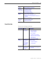
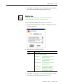
Related Documentation
The following documents contain additional information concerning
related Allen-Bradley products. To obtain a copy, contact your local
Allen-Bradley office or distributor.
Publication
Number
For
Read this Document
Information regarding ULTRA Plus
hardware
ULTRA Plus Installation and
Setup Manual
1398 - 5.1
An overview of the ULTRA Series
family
ULTRA Series
Digital Servo Drives
1398 - 1.0
An overview of ULTRA Plus Positioning
Servo Drives
ULTRA Plus Positioning Servo
Drives
1398 - 1.1
Descriptions and specifications for the
ULTRA family
ULTRA Series Product Data
1398 - 2.0
An article on wire sizes and types for
grounding electrical equipment
National Electrical Code
Published by the
National Fire
Protection
Association of
Boston, MA.
A complete listing of current AllenBradley documentation, including
ordering instructions. Also indicates
whether the documents are available
on CD-ROM or in multi-languages
Allen-Bradley Publication Index
SD499
A glossary of industrial automation
terms and abbreviations
Allen-Bradley Industrial
Automation Glossary
AG - 7.1
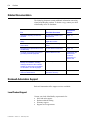
Rockwell Automation Support
Rockwell Automation offers support services worldwide.
Local Product Support
Contact your local Allen-Bradley representative for:
l
Sales and order support
l
Product technical training
l
Warranty support
l
Support service agreements
Publication 1398-5.11 - February 1997
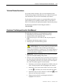
Common Techniques Used in this Manual
P-5
Technical Product Assistance
If you need technical assistance, first review the information in the
Troubleshooting chapter of the GML Ultra User Manual. If you need
more information, call your local Allen-Bradley representative.
For the quickest possible response, we recommend that you have the
catalog numbers of your products available when you call. Refer to
Where to Find Help for the publication numbers related to this product.
The Rockwell Automation Technical Support number is
(216) 646-6800.
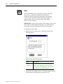
Common Techniques Used in this Manual
The following conventions are used throughout this manual:
l
Bulleted lists provide information, not procedural steps.
l
Numbered lists provide sequential steps.
l
Words that you type or select and keys that you press appear in
bold.
l
Field names and references appear in italics.
l
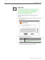
Warnings appear with the following symbol:
ATTENTION: This warning identifies information about
practices or circumstances that can lead to personal injury or
death, property damage, or economic loss. This symbol indicates a
situation that requires immediate attention for personnel safety or
for preventing harm to machinery .
l
l
IMPORTANT: Identifies information that is critical for successful
application and understanding of the product.
The term “select” means that you use your mouse cursor to point to
the value, then click-and-release the left mouse button to mark your
choice. Depending on the field, you can select one or more options
for a field. The options appear in various formats:
l
l
Sometimes you must browse through a list to find the value you
want. Clicking an option in the list highlights your selection.
Sometimes you can select several values in one area. A check
in a box
l
l
is used when you can select more than one option.
Sometimes only one value is allowed. A radio button
when you can select only one option.
is used
When you select a block in your diagram, the block is
highlighted. You can now:
Publication 1398-5.11 - February 1997
P-6
Preface
l
l
Move the block by clicking and dragging, rather than
clicking and releasing.
Open the dialog box by double-clicking.
In all cases, the term indicates your choice to GML Ultra.
Publication 1398-5.11 - February 1997
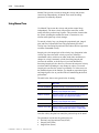
Chapter 1
GML Ultra Overview
GML, the exclusive Graphical Motion Control Language from AllenBradley, provides a graphical method of programming your motion
controller. This revolutionary tool reduces the time you need to learn
motion control programming and makes problem-solving easier. GML
integrates software programming and debugging to solve your motion
control problems. GML Ultra, a member of the GML family, is a
Microsoft® Windows®-based interface to the ULTRA Plus series of
controllers.
How it Works
GML Ultra uses a flowchart approach to motion control programming.
To produce a diagram (motion program), you place function blocks
(representing the specific actions) on the screen, then connect them in
the proper order of operations.
Later you enter motion and process limits, using a fill-in-the-form
approach. Each block has its own form, which you select with a few
clicks of the mouse. You can enter and change any block at any time,
minimizing the need to consult a manual or understand any specialized
syntax.
After you complete the diagram, you download it to a controller, where
it is translated into a program or script in the native language of the
motion controller.
You need a PC for program development but you do not need it for the
final turn-key application.
Encapsulating, which combines two or more blocks into a module, is a
unique function of the GML Ultra graphical interface. You can
duplicate the module, use it again in the same diagram, use it in another
program, or save it as a diagram file in a library folder for use in
subsequent diagrams.
Motion Controllers that Use GML Ultra
GML Ultra is designed for the Allen-Bradley ULTRA Plus series of
controllers, a family of 1½ axis digital servo and positioning servo
drives designed for a wide range of applications.
Publication 1398-5.11 - February 1997
1-2
GML Ultra Overview
The ULTRA Plus series Positioning Drive Module (PDM) combines a
drive and a controller to create a powerful, self-contained,
1 ½ axis programmable motion controller.
Personality Module for ULTRA Plus Controllers
The Personality Module (PM) is a nonvolatile memory device that
stores the information necessary to customize an ULTRA Plus
controller for a specific application. The PM holds parameters to match
the motor and the controller, as well as user programs and parameters.
A Personality Module can be physically removed and transferred to
another ULTRA Plus controller if the replacement of a controller is
necessary to simplify servicing the machine. The Personality Module
data can also be saved in a computer file and loaded into the ULTRA
Plus controller using the upload options in Online Manager.
Communications for ULTRA Plus Controllers
The following basic communication links are pre-installed in all
ULTRA Plus controllers.
l
RS-232
l
RS-422
l
Multi-drop
RS-232
RS-232 is an industry-defined electrical interface standard for serial
communication.
RS-422
RS-422 is a hardware standard that defines a method for transmitting
high-speed serial data over very long distances using a balanced,
twisted-pair transmission line.
Multi-drop mode
All ULTRA Plus controllers can be configured to operate in
multi-drop mode. This mode allows up to ten controls to share a single
RS-422 communication link by using two special non-echoed
commands to activate individual units. The individual units then
respond to commands issued by the operator interface device or by the
host computer.
Publication 1398-5.11 - February 1997
Chapter 2
Before you Begin
Before you begin using GML Ultra, read this chapter to become
familiar with:
l
Your work area
l
Your tools
Understanding Your Work Area
GML Ultra provides several work areas made up of windows. Some
windows are active only when you are online. Sometimes a window, or
a portion of a window, changes function, depending on other options,
such as your operating mode.
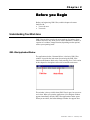
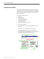
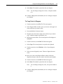
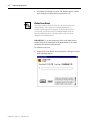
GML Ultra Application Window
The application window, illustrated below, is the basic GML Ultra
window. It provides the main menu for accessing the GML Ultra
functions and features. Refer to the Understanding Your Tools section
in this chapter for descriptions of the title bar and the main menu.
This window is always visible when GML Ultra is open, but you never
see it alone. When you open the application, a New Diagram window
appears immediately after the GML Ultra application window opens.
When you are online, the Online Manager window also appears here.
Publication 1398-5.11 - February 1997
2-2
Before you Begin
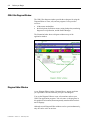
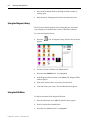
GML Ultra Diagram Window
The GML Ultra diagram window provides the workspace for using the
Diagram Editor to create, edit, and test programs. It also provides
access to:
l
l
all the menus and toolbars
the block palette, definitions menus, setting breakpoints, translating
diagrams to script function, and the Online Manager
The illustration below shows a diagram window on top of the
application window
Diagram Editor Window
A new Diagram Editor window, illustrated above, appears each time
you open GML Ultra and each time you open a new diagram.
You use the Diagram Editor to create, edit, translate, and test your
GML Ultra application programs. You can create or edit programs in
this graphical environment, then transparently translate them into their
native language.
Although several Diagram Editor windows can be open simultaneously,
only one can be active at one time.
Publication 1398-5.11 - February 1997
Understanding Your Work Area
2-3
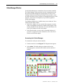
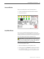
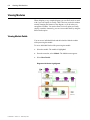
Online Manager Window
Use the Online Manager to communicate with your motion controller.
The Online Manager window provides real-time communication with
the motion controller through the scripted program. It allows you to
exchange information and control processing. It also provides a venue
to monitor and supervise the execution of commands and partial or total
programs. Tools (such as breakpoints) are provided for graphical
testing and debugging.
Two additional windows are available when you are online; the Trace
window and the Watch window
l
l
In the Trace window, you can visually follow program execution.
GML Ultra highlights each block or module as the program in the
motion controller executes that block. For more information, refer
to the Trace Window section in this chapter.
In the Watch window, you can watch a command function as it
executes in a program. For more information, refer to the Watch
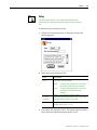
Window section in this chapter.
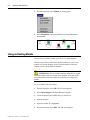
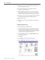
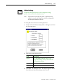
Accessing the Online Manager
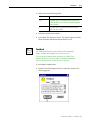
To communicate with your motion controller:
1.
From the menu bar, select Diagram. The Diagram menu appears.
2.
Select Online. The Online Manager window similar to the
following appears; communication with the motion controller is
enabled.
Publication 1398-5.11 - February 1997
2-4
Before you Begin
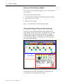
Moving the Online Manager Window
You can move the Online Manager window to a more convenient place
on your screen.
To move the Online Manager window:
1.
Click in the title bar and hold the mouse button down as you drag
the window to a new position.
2.
Release the mouse button.
Note:
You cannot resize the Online Manager window.
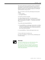
Viewing Both Diagram Editor and Online Manager
You can move easily between the Diagram Editor window and the
Online Manager window. If you click on your diagram while the Online
Manager window is open, the diagram moves to the front and the
Online Manager window moves to the back. We recommend that you
resize your diagram window so both windows are visible at the same
time, similar to the following:
For information on using the Online Manager to communicate with
your controller, refer to the Going Online chapter.
Publication 1398-5.11 - February 1997
Understanding Your Work Area
2-5
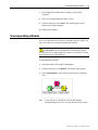
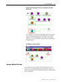
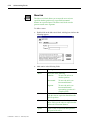
Trace Window
The Trace window looks similar to the Diagram Editor window, which
it replaces when you are online. In the Trace window, however, each
block or module is highlighted as the program (partial or total) in the
motion controller executes that block, allowing you to visually follow
program execution. Tools such as breakpoints are provided for
graphical debugging.
The following graphic shows the Trace window as:
The first block executes:
The second block executes:
The third block executes:
The first block executes again:
Publication 1398-5.11 - February 1997
2-6
Before you Begin
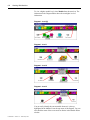
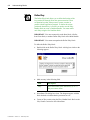
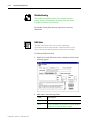
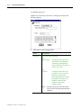
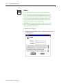
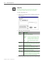
Watch Window
When working online, you use the Watch window to monitor a variable
as it executes in the program.
If you have not already identified the items you want to watch, a dialog
box alerts you to do so. The following Watch Items dialog box is
similar to the one you use to select the tags you want to monitor.
Publication 1398-5.11 - February 1997
Understanding Your Work Area
2-7
Command Window
When you are working online, use the Command window to:
l
View the command and/or response links with the controller.
l
Execute block functions.
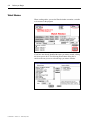
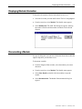
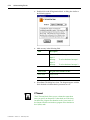
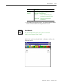
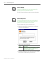
Script Editor Window
Some of you are comfortable identifying problems from the script
version of the diagram. Use the Script Editor to view and edit text files,
including script documents generated from GML diagram documents.
Note: Your computer must be online to download a script.
ATTENTION: If you make changes to the script, they are not
converted back to the graphical diagram. Once you make a change to a
program’s script, you cannot go back to working in GML mode. We
suggest that you use script only for viewing, not editing.
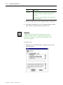
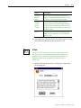
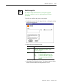
To access the Script Editor window:
1.
Make sure the diagram you want to translate is active.
2.
From the menu bar, select Diagram. The Diagram menu appears.
3.
Select Translate to Script. Upon successful translation, a script
file similar to the following appears in the Script Editor window.
Publication 1398-5.11 - February 1997
2-8
Before you Begin
For more information on using the Script Editor to view and fine tune
your program, refer Translating to Script.
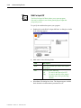
Quick Reference to GML Ultra Windows
Work area
Purpose
Available
Off line
Available
Online
Application Window
Access to the main menu for GML Ultra functions
and features.
4
4
Diagram Window
Workspace for using the Diagram Editor to create
and edit diagrams.
4
4
Diagram Editor Window
Provides functions and features to create and edit
diagrams.
4
Online Manager Window
To communicate in real-time with your motion
controller.
4
Trace Window
Online, to monitor the sequence of blocks
executing in a program. For debugging.
4
Watch Window
Online, to monitor a variable as it executes in a
program.
4
Command Window
Online, to monitor a command and/or response
link with the controller.
4
Script Editor window
To view and edit text files, including script
documents generated from GML documents.
Publication 1398-5.11 - February 1997
4
4
Understanding Your Tools
2-9
Understanding Your Tools
Title Bar
The GML Ultra title bar shows the name of your diagram along with
the size and close controls. Use the Title Bar to locate a diagram in the
window. If you have not yet named or saved your diagram, the diagram
is temporarily named New Diagram. Subsequent unnamed diagrams are
also named New Diagram. For example, when you open a new
diagram, you see the following:
Refer to Naming Your Diagram, in the Working With Diagrams
section.
After you save a diagram, the name changes, similar to the following:
Note:
GML Ultra automatically adds the .ULT suffix to the name of
your diagram.
Main Menu
The main menu is at the top of the window. It provides access to the
primary GML Ultra functions.
Refer to Using the Diagram Menu for a description of each menu
option.
Block Palettes and Libraries
The colored building blocks are the graphical elements you use to create
a diagram.
For instructions on selecting and placing blocks in a diagram, refer to
the Working with Blocks chapter.
For a brief description of each block, refer to the Understanding Blocks
chapter.
For detailed information on blocks, refer to the GML Ultra Reference
manual.
Publication 1398-5.11 - February 1997
2-10
Before you Begin
Block Palette
The on-screen palette shows the most recently used blocks.
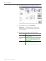
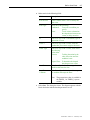
Block Libraries
The Block Library varies depending on the type of diagram you are
building. There are three block libraries.
This specialized
module
Does this
Places a new blank module on the diagram.
You can use this module in two ways:
Contains this
set of blocks
All GML Ultra
blocks.
When you use this module once, it acts as the
container for the entire diagram. The control code
it produces is placed in the main program if you
do not define modules in the call table. For
example, a new diagram is really a New Module
block.
When you encapsulate or add a New Module
block to your diagram, a sub-routine is created
and a call to that sub-routine occurs with each
use.
Places a new blank Scan Event Handler module in
the diagram.
Scan Event Handlers monitor the condition of
scan events. If the condition is true and the scan
event is enabled when scanned, the actions are
performed in parallel with program execution. You
can enable and disable scan events in the
application.
Places a new blank Xkey Handler module in the
diagram.
Xkey Handlers perform their actions in parallel
with program execution. The keys on the Operator
Terminal marked X1 through X4 are special
purpose keys that, when pressed, cause the
execution of an Xkey Handler.
Publication 1398-5.11 - February 1997
Blocks that are
relevant to scan
events.
Blocks that are
relevant to Xkey
functions.
Understanding Your Tools
2-11
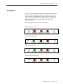
Color Code for Blocks
GML uses color to group blocks by function.
Color
Function
Green
Initiate or change motion
Red
Stop motion
Yellow
Change setting or configuration
Brown
Affect program flow control
Pink
Provide I/O control
Violet
Provide operator interface functions
Light Green
Provide communications facilities
Light Yellow
Provide calculations, tables, and other similar
functions
White
Provide miscellaneous functions that are not
available in the categories above
Publication 1398-5.11 - February 1997
2-12
Before you Begin
Publication 1398-5.11 - February 1997
Chapter 3
General Procedures
This chapter contains step-by-step procedures for tasks you use
frequently while programming in GML Ultra. These tasks include the
following:
l
Starting GML Ultra
l
Creating new diagrams and scripts
l
Opening diagrams and scripts
l
Saving and naming a diagram
l
Naming blocks and modules
l
Printing diagrams and scripts
l
Closing a file
l
Exiting GML Ultra
Starting GML Ultra
To start GML Ultra, double-click on the GML Ultra icon.
The GML Ultra application window appears with a new, active,
unnamed diagram window.
Creating New Files
One of GML Ultra’s time-saving features is its ability to use existing
diagrams to create new ones, and to save diagrams or parts of diagrams
for this purpose. Also, GML Ultra supplies a library of generic
diagrams/modules that are designed for use in your diagrams.
You can create a new file in two ways:
l
Select New Diagram or New Script from the File menu.
l
Save an existing diagram or script with a new name using Save As
from the File menu.
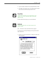
Creating a New Diagram
When you have a diagram open, you can start to work on another. Your
application is already active — you just need a new Diagram Editor window
to build a new diagram. Use this option to open a new GML Ultra Diagram
Editor window in which you build a new diagram.
1. From the menu bar, select File. The File Menu appears.
Publication 1398-5.11 - February 1997
3-2
General Procedures
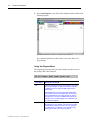
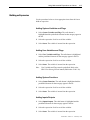
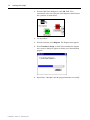
2. Select New Diagram. A new GML Ultra diagram window similar to the
following appears:
For a detailed explanation of this window, refer to the Before You
Begin chapter.
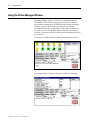
Using the Diagram Menu
The diagram menu located at the top of the window provides access to
the primary GML Ultra functions.
This menu
Gives you access to
File
Standard Windows functions (such as open, save, print
and close) that apply to GML Ultra diagrams and files.
In addition it has one important GML Ultra function,
Preferences.
Use Preferences to set general program parameters
that remain constant in your application environment.
These parameters do not change unless you elect to
change them. You need not address this option if the
settings for your current diagram are no different from
your previous diagram.
Edit
Publication 1398-5.11 - February 1997
Options that pertain to the Diagram Editor and the
development of your diagram. Use this menu to make
normal editing changes (such as cut, copy, paste) to
your diagram as you develop it. You can also make
other types of edits, such as moving blocks.
Creating New Files
This menu
Gives you access to
Definitions
Dialog boxes that you use to tell your computer about
your motion controller. The GML Ultra menus are
customized based on the information provided.
Module
Options for encapsulating blocks into modules and
accessing module details.
Diagram
Statistical information such as number of modules and
blocks in the diagram. Access to diagram functionality,
such as testing, online connection, translating to script,
and the find function.
Windows
All open GML Ultra windows from which you can select
the one you want to view.
Help
GML Ultra’s online help functions.
3-3
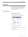
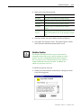
Creating a New Script
A script is the text equivalent of a graphic-based diagram. Use the New
Script option to write a program using script instead of using the
graphical interface.
IMPORTANT: We recommend that you use the New Diagram option
to develop new programs.
To create a new script document:
1. From the menu bar, select File. The File menu appears.
2. Select New Script. A GML script window appears.
Publication 1398-5.11 - February 1997
3-4
General Procedures
Using the Script Menu
The Script window displays menu options pertaining to writing,
importing, and downloading scripts.
This menu
option
Provides access to these features
File
Open new and existing diagrams and scripts, print
functions, and general GML Ultra system settings.
Edit
Standard text editing functions.
Script
Find/Replace.
Windows
A list of active diagrams and scripts.
Help
GML Ultra online help.
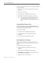
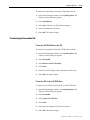
Opening Existing Files
Opening a Diagram
You can access previously written and saved functional modules (saved
as diagrams) and entire diagrams to build your new diagram. When the
diagram opens, you can:
l
Edit or further develop a previously saved diagram.
l
Copy formatted blocks, modules, or larger portions of the diagram
for use in another diagram (a primary benefit of GML’s graphical
design structure.)
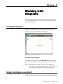
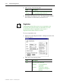
To access a diagram:
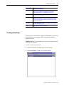
1. From the menu bar, select File. The File menu appears.
2. Select Open Diagram. The Open dialog box appears.
Publication 1398-5.11 - February 1997
Opening Existing Files
3-5
3. Locate the diagram file you want to open.
Note: The file must have a .ULT extension.
4. Select the diagram you want by double-clicking on the name of the
file. The file opens and the Diagram Editor window appears.
You can now:
l
Make changes to the diagram.
l
Copy portions or blocks.
l
Convert the diagram to script.
l
Download the diagram to your controller.
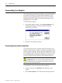
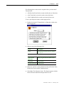
Opening a Script
Use the Open Script option to open a saved script. You can then copy
all or portions of the script as you build your new program. When the
existing script opens, you can:
l
Edit or further develop the existing script.
l
Copy portions of the script for reuse in another script.
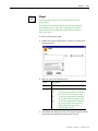
To access an existing diagram:
IMPORTANT: Once you convert a diagram to script, the procedure
cannot be reversed. The script text is the actual language used for the
motion controller program.
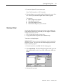
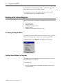
1. From the menu bar, select File. The File Menu appears.
2. Select Open Script. The Open dialog box appears with *.qps text
files identified the List files of type field, similar to the illustration
below.
3. Select the file you want.
Publication 1398-5.11 - February 1997
3-6
General Procedures
4. Select Open. The script file opens in the window similar to the
illustration below.
You can now:
l
Make changes to the script
l
Select and copy portions of the script to another file
l
Download the script
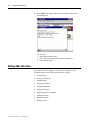
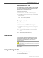
Editing GML Ultra Files
It is common to make changes as you work on a diagram. Use the
following options on the Edit menu to make the changes.:
Publication 1398-5.11 - February 1997
l
Cutting blocks
l
Clearing information
l
Deleting blocks
l
Copying information
l
Pasting information
l
Selecting a diagram
l
Duplicating part of a diagram
l
Undoing an action
l
Redoing an action
l
Editing a script
Editing GML Ultra Files
3-7
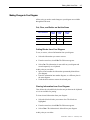
Making Changes to Your Diagram
All the tools you need to make changes to your diagram are available
through the Edit menu.
Cut, Clear, and Delete are Not the Same
This command
Allows
undo
Allows
redo
Allows
paste
Cut
8
8
8
Clear
8
8
Delete
8
Cutting Blocks from Your Diagram
To cut, or remove, selected information from your diagram:
1.
Select the information you want to remove.
2.
From the menu bar, select Edit. The Edit menu appears.
3.
Select Cut. The information is removed from your diagram and
stored temporarily on a clipboard.
At this point you can either:
l
Ignore it and consider the information permanently deleted from
your diagram.
l
Paste the information into another diagram, or a different place in
the same diagram.
l
Undo the delete action to restore the selected parts.
Clearing Information from Your Diagram
Clear deletes the selected blocks, but does not put them on the clipboard
so it is not available for pasting.
To clear selected information from your diagram:
1.
Select the block or blocks you want to clear. The blocks are
highlighted.
2.
From the menu bar, select Edit. The Edit menu appears.
3.
Select Clear. The information is deleted from your diagram.
At this point you can either:
Publication 1398-5.11 - February 1997
3-8
General Procedures
l
l
Ignore it and consider the information permanently deleted from
your diagram.
Undo the delete action to restore the selected parts.
Deleting a Block from a Diagram
If you place a block in the Diagram Editor window and then change
your mind, you can delete it.
To delete a block:
1.
Select the block.
2.
Press Delete.
3.
At this point you can either:
Ignore it and consider the information permanently deleted from
your diagram.
Undo the delete action to restore the selected parts.
l
l
Copying Blocks
You can copy any block or group of blocks along with their associated
parameters. Copying has no effect on the original diagram, leaving the
selected blocks exactly as they were. When you copy a module, the
copied information includes all the blocks, connections, parameters, and
other modules contained in the module.
The primary purpose of Copy and Paste is to allow you to repeat
information in another location easily.
l
l
ATTENTION: Not all the information is transferred.
Axis name is not transferred.
Use of variables is not transferred.
You can copy information from one diagram and paste it into another:
l
Diagram.
l
Location in the same diagram.
To copy:
1.
Select the information you want to copy.
2.
From the menu bar, select Edit. The Edit menu appears.
3.
Select Copy. The information is stored on a clipboard.
Note:
Publication 1398-5.11 - February 1997
The information remains on the clipboard until you
perform another Copy or Cut.
Editing GML Ultra Files
3-9
Pasting Information into Your Diagram
The information that you want to paste can originate from either a Cut
or a Copy. GML Ultra allows you to paste the information multiple
times.
Publication 1398-5.11 - February 1997
3-10
General Procedures
To paste the contents of the clipboard in the same diagram window that
you cut or copied from:
1.
Place your cursor at the location at which you want to put the
information.
2.
Click the left mouse button.
3.
From the menu bar, select Edit. The Edit menu appears.
4.
Select Paste. The copied information appears in the diagram.
Note:
The information on the clipboard remains there until you
cut or copy something else, which then replaces the
previous information. The clipboard only holds one item at
a time.
Selecting a Whole Diagram at Once
This option selects all the elements in the Diagram Editor window.
Select All is most often used in combination with other editing changes
to your diagram, such as aligning and spacing.
To select the entire diagram:
1.
From the menu bar select Edit. The Edit menu appears.
2.
Select Select All. Every block, module, and connection is
highlighted.
Note:
At this point the information is NOT copied.
Duplicating Part of Your Diagram
Duplicate creates an identical block or set of blocks in the same
diagram. Those blocks can then be moved to a different location in the
diagram.
To create an identical block or group of blocks:
Publication 1398-5.11 - February 1997
1.
Select the information to be duplicated. The block(s) are
highlighted.
2.
From the menu bar, select Edit. The Edit menu appears.
3.
Select Duplicate. A second block or set of blocks appears in the
diagram. The new set is highlighted.
4.
Drag the new blocks to the new location.
Saving and Naming a New File
3-11
Undoing the Most Recent Action
You can undo an action if you make a mistake or change your mind.
You only have one chance to undo and you must perform the undo
immediately after the action you want to undo.
To undo your most recent action.
1.
From the menu bar , select Edit. The Edit menu appears.
2.
Select Undo. The diagram returns to the way it was immediately
before your action.
Note:
You can undo only one action.
Redoing Your Last Action
To redo your last action:
1.
From the menu bar, select Edit. The Edit menu appears.
2.
Select Redo. The last action you performed on your diagram is
repeated.
Note:
If you select Redo after an undo, the action you undid is
redone.
Note:
Undo and Redo go backwards one step.
Editing Your Script
Use the Script Editor window to view and edit text files, including
script documents generated from GML Ultra diagram documents.
Script Editor provides standard cut, copy, paste, delete, and
find/replace functions.
ATTENTION: Changes to the script cannot be converted back
to the graphical diagram.
For more information on using scripts, refer to the Working with
Scripts chapter.
Saving and Naming a New File
Use the following procedures for saving files:
l
Saving and naming a diagram
Publication 1398-5.11 - February 1997
3-12
General Procedures
l
Saving changes to a diagram
l
Changing a Diagrams name and location
Saving and Naming a New Diagram
IMPORTANT: Save and name your new diagram, even though it is
empty.
The first time you save your diagram, you are required to:
l
Name the diagram.
l
Place the diagram in a specific folder, in a specific location.
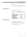
Saving Changes to a Diagram
We recommend that you save any changes to the diagram (new blocks,
new modules, new connections, new parameter settings.)
To save changes to a diagram.
1.
From the menu bar, select File.
2. Select Save. All changes since the last save are saved.
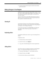
Changing a Diagram’s Name and Location
You can save the current diagram under a different name and/or in a
different location.
Naming a Block
When you first create a block, the description below it is generic. You
probably want to rename it using a descriptive name reflecting the
block’s function within this program. When you place the block, the
description below it is highlighted.
To name a block:
Publication 1398-5.11 - February 1997
1.
With the left mouse button, click in the name area below the block.
2.
Type a descriptive block name.
Naming a Module
Note:
3.
3-13
You can type a name and up to four additional lines
describing the block. There is no word wrap, so press
ENTER after each line.
When you are finished, click any blank area in the diagram. The
block is released and the new name appears.
Naming a Module
When you create a module, GML Ultra assigns it the name New
Module x.
Note:
The first module, New Module, is counted as zero.
To make your diagram easier to identify, give the module a more
descriptive name:
1.
Select the box below the icon that contains the name. The box is
highlighted.
2.
Type a descriptive name reflecting the combined functions
represented by the module.
ATTENTION: Because GML Ultra uses the first line to
identify modules, it must contain a unique identifier. For modules
the first line can be up to 32 characters long. For blocks, the first
line can be up to 64 characters long.
3.
To document the functionality of the module within the diagram,
type up to four lines of additional information in this box.
Note:
4.
Press ENTER after each line.
Click on an area outside the module to deselect the module.
Publication 1398-5.11 - February 1997
3-14
General Procedures
Printing Files
Use the following procedures for printing:
l
Setting up the printer
l
Printing a diagram
l
Printing a picture of all diagram modules
l
Printing a picture of select diagram modules
l
Printing a script
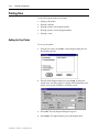
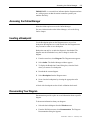
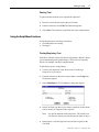
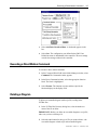
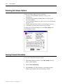
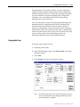
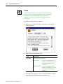
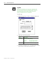
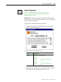
Setting Up Your Printer
To set up your printer:
Publication 1398-5.11 - February 1997
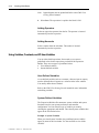
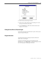
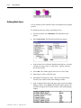
1.
From the File menu, select Print. A Print Diagram dialog box like
the following appears.
2.
From the Print Diagram dialog box, select Setup. A dialog box
similar to the one below appears. Complete the fields based on your
printer, your version of Windows, and other criteria.
3.
Select OK. The Print Diagram dialog box appears.
4.
Select Print. The diagram and/or parts of the diagram print.
Printing Files
3-15
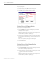
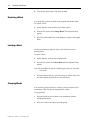
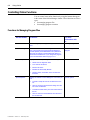
Printing a Diagram
For a printed record of all or parts of your diagram, you can print:
l
Only the diagram
l
The diagram and all the modules
l
The diagram and some of the modules
l
Only the modules
l
Only some of the modules
For each selection, you can choose to print:
l
Details
l
Descriptions
l
An index
Publication 1398-5.11 - February 1997
3-16
General Procedures
To print your diagram:
1. From the menu bar, select File. The File menu appears.
2. Select Print. The Print Diagram dialog box appears.
Printing a Picture of All Diagram Modules
To print a picture of all diagram modules
1. Select All Modules. All modules, including the top level module
(the diagram itself) are printed.
Modules are printed exactly as they appear on the computer screen
and each module is printed on a separate page.
2. Select the type of information you want to print about each module.
For a description of information types, refer to the table in the next
procedure.
Note: You can print only four pages for each diagram.
3. Select the Print button.
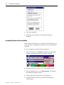
Printing a Picture of Select Diagram Modules
To print a picture of select modules:
1. Select Selected Modules. All the modules in the diagram are listed
in the window (including the diagram itself).
2. From the module list, select the modules you want to print. A check
( ) appears in front of the selected modules.
Modules are printed exactly as they appear on the computer screen
and each module is printed on a separate page.
Publication 1398-5.11 - February 1997
Closing a File
3-17
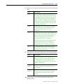
3. Select one or more information types you want to print about each
module. Use the information in the following table.
Field
Description
Print Details
To print a page describing the parameter
values for each block.
Note:
Print Definitions
Print Index
Each block is assigned a numeric
identifier and is printed on a
separate page.
To print a page describing the module
definitions for each selected module.
To print an index containing a page
reference for each module that has been
printed.
4. Select Print.
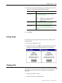
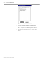
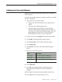
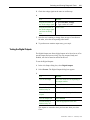
Printing a Script
For a hard copy of your program script to edit or keep on file, print a
script as follows:
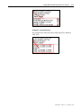
1.
Convert your diagram to script.
2.
From the File menu, select Print. The print function begins. Status
dialog boxes similar to the following appear. The script prints.
Closing a File
You can close a file at any time. You need not be finished with the diagram.
The system saves whatever you have completed. Use the following
procedures:
l
Closing a file before saving it.
l
Closing a file that is saved and named
Publication 1398-5.11 - February 1997
3-18
General Procedures
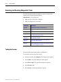
Closing a File Before Saving It
A diagram is considered new until it is saved. Usually, you name a
diagram when you first save it. If you close a file without saving it,
your work is lost.
To close a diagram:
1.
From the menu bar, select File.
2.
Select Close. The following dialog box appears.
3.
Select Yes. The Save As dialog box appears. The name is
highlighted in the File name field.
4. In the File name field, type a new file name.
5. Confirm the path where the file is saved.
Publication 1398-5.11 - February 1997
Exiting GML Ultra
3-19
6. Select OK. The file is named, saved, and closed. The GML Ultra
window appears with the new name in four places: the diagram
Title Bar, the module list, and beneath the START and END blocks.
If other files are open in GML Ultra, they appear when the current
file closes.
Closing a File Already Saved and Named
Normally, you have named your diagram, and saved it periodically
during the diagram development process.
To close a file.
1.
From the menu bar, select File. The File menu appears.
2.
Select Close. The file closes.
If other GML
Ultra files are
This happens
Open
They appear when the current file is
closed.
Not open
The window is blank.
Exiting GML Ultra
1. From the menu bar, select File. The File Menu appears.
2. Select Exit. GML Ultra checks all open documents for changes and
asks if each changed document should be saved before quitting.
3.
The GML Ultra application closes.
Publication 1398-5.11 - February 1997
3-20
General Procedures
Note:
Publication 1398-5.11 - February 1997
To close only a file within the application, select Close, not
Exit, from the File Menu.
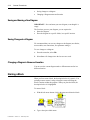
Chapter 4
Working With Blocks
To create a program or diagram in GML Ultra, you place blocks
and
representing program functions between the
blocks. These two blocks are always present in the diagram and cannot
be deleted. You generally add blocks left to right in the Diagram Editor
window. You then connect the blocks to show the flow of program
functions. You can move blocks around and change their connections,
which changes program flow. You can simplify complex diagrams by
grouping (encapsulating) several blocks together, then giving the
module a name that describes the group’s function.
To make working with blocks easier, we recommend that you:
l
Try to have block connections flow from left to right or up to down.
l
Limit the number of blocks in the work space to ten or less.
l
Try to keep your diagram on one screen so that you don’t need to
scroll to see parts of it.
This chapter covers:
l
The physical aspect of blocks, such as selecting, moving, and
naming.
l
Using blocks to define functions for your diagram and using the
Expression Builder.
Selecting and Positioning Blocks on the Diagram Editor Window
There are two ways to select and position blocks in the Diagram Editor
window:
l
Selecting a block from the Diagram Library.
l
Picking and placing a block from the block palette.
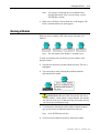
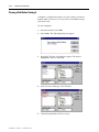
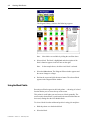
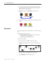
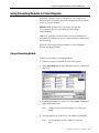
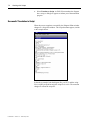
Using the Diagram Library
The Diagram Library contains all available blocks for your motion
controller.
To access blocks from the Diagram Library:
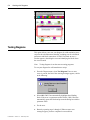
1.
At the far left of the block palette, select the Library Browser
block.
Publication 1398-5.11 - February 1997
4-2
Working With Blocks
The Diagram Library, similar to the following, appears:
Note:
2.
More blocks are available by sliding the scroll bar down.
Select a block. The block is highlighted and a description of the
block’s function appears in the text area on the right.
Note:
In the example above, the Move Axis block is selected.
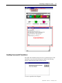
3.
Select the Select button. The Diagram Editor window appears and
the cursor changes to a finger.
4.
Position the cursor and click the mouse button. The selected block
appears in the Diagram Editor window.
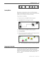
Using the Block Palette
Recently used blocks appear in the block palette — the string of colored
function blocks you see across the top of the screen.
This palette is useful when you need to reuse a block repeatedly. The
most recently selected block is positioned in the next block that has not
been used, starting after the New Module block.
To select a block from the toolbar and position it using pick and place:
Publication 1398-5.11 - February 1997
1.
Hold the pointer over the desired block.
2.
Select the block.
Manipulating Blocks
Note:
4-3
Do not hold down the mouse button.
3.
Place the cursor into position in the Diagram Editor window.
4.
Click and release the mouse button. The block appears in the
diagram.
Manipulating Blocks
Most blocks and modules, including the START and END blocks, have
input and output nodes. The diagram must start at the START block. It
also must have connections drawn from an output node of one block to
the input node of another. The diagram usually ends at the END block,
but does not need to.
Using the Cursor
When you build a diagram, the cursor acts as three separate tools:
l
A pointer allows you to select and move blocks.
l
A soldering iron allows you to connect blocks.
l
A wire cutter allows you to remove connections.
Connecting Blocks
To connect blocks and modules:
1.
Move the cursor to the desired output node. The cursor changes
from a pointer to a soldering iron.
2.
Press and hold the mouse button.
3.
Drag the soldering iron to the desired input node or anywhere inside
the icon. As you drag, a green line representing the connection is
drawn.
4.
When the soldering iron is in the appropriate location, release the
mouse button. The connection is complete.
Publication 1398-5.11 - February 1997
4-4
Working With Blocks
Moving Blocks
You can drag blocks, including the START and END blocks, anywhere
in the diagram. Their connections remain no matter where you move
them.
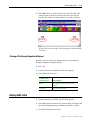
Showing the Connection Lines
Use the Diagram Drawing option (select Preferences from the File
menu) to show connection lines:
l
On top of blocks to help keep track of connections in the
foreground..
l
Underneath blocks to show blocks in the foreground.
Disconnecting Blocks
To cut a connection:
1.
Move the pointer to a connecting line. The cursor changes to a wire
cutter.
Note:
2.
You can only cut horizontal connecting lines.
Click your left mouse button. The connection is cut.
In some cases, when you have a connection that loops back to an earlier
block in the diagram, you could want to move a vertical connection to
avoid other blocks. To move lines:
1.
Place the pointer on the vertical connecting line. A double arrow
replaces the pointer.
Publication 1398-5.11 - February 1997
Making Changes to Your Diagram
2.
4-5
Press the left mouse button, drag the connection to the desired
position and release.
Making Changes to Your Diagram
All Edit menu options pertain to the Diagram Editor window. You use
this window to make standard editing changes to your diagram, such as
cut, copy, paste. Descriptions of these options are in the General
Procedures chapter.
You also use this menu to select editing features that are specific to
GML Ultra, such as moving blocks and accessing block parameters.
These options are described in this section.
Selecting All
Use the Select All option to select all the elements in the Diagram
Editor window. This option is often used with other editing changes to
your diagram, such as aligning and spacing.
To select the entire diagram, select Select All from the Edit menu.
Every block, module, connection, property, and parameter is
highlighted.
Duplicating a Block
Use Duplicate on Edit menu to make a copy of an existing block in a
diagram.
To duplicate a block:
1. Select the block you want to duplicate.
2. From the File menu, select Duplicate.
3. A copy of the selected block appears next to the original block.
Adding a Block
You add a new block to a diagram by selecting it from the Diagram
Library. You can display the Diagram Library in two ways:
1. Click on the Library Browser — the first block on the left.
2. From the File menu, select Add.
3. Move the cursor when you want to add a block.
Publication 1398-5.11 - February 1997
4-6
Working With Blocks
4. Click the left mouse button. The block is added.
Replacing a Block
You can quickly replace one block on the diagram with another block.
To replace a block:
1. On the diagram, select the block you wish to replace.
2. From the File menu, select Change Block. The Diagram Library
appears.
3. Select the replacement block; in the diagram, it replaces the original
block.
Inserting a Block
Use the Insert Between option to insert a new block between two
existing blocks.
To insert a block:
1. On the diagram, select the two existing blocks.
2. From the File menu, select Insert Between. The Diagram Library
appears.
Note: The Insert Between option is disabled (gray) until you select the
two blocks.
3. From the Diagram Library, select the block you wish to insert. The
new block appears between the two selected blocks.
Grouping Blocks
You can treat a group of blocks as a unit by placing a temporary box
around them. They can then be manipulated as a group.
To group blocks:
Publication 1398-5.11 - February 1997
1.
Place the blocks so you can draw a box around them without
including other blocks.
2.
Place your cursor at the upper left of the group.
Making Changes to Your Diagram
4-7
3.
Press and hold the left mouse button and drag it to the lower right
of the group. A box is drawn around the group.
4.
Release the mouse button. The blocks are highlighted.
You can now work with the block group as a unit. For example, you
can move (as shown above), cut, or encapsulate the blocks as a group.
For more information about encapsulating blocks, refer to the
Encapsulating Blocks section.
Swapping Blocks
Use the Swap Blocks option to swap the location and connections of
two selected blocks. The blocks need not be connected.
In the example that follows, the Control Settings block is swapped with
the Output block.
This is the current position of the blocks.
To swap two selected block positions in a diagram:
1.
Select one of the blocks to be swapped by selecting it with your left
mouse button. It is highlighted.
Publication 1398-5.11 - February 1997
4-8
Working With Blocks
2.
Select the second block to be swapped by holding down the Shift
key and clicking the second block with your left mouse button. You
should now have two selected blocks.
3.
From the Edit menu select Swap Blocks, The blocks switch
positions.
4.
Click your left mouse button in another area of the pane to clear the
selection.
Aligning Blocks
Use the Align Blocks option to align blocks on a vertical or a horizontal
grid.
The Align Blocks option affects either:
l
The entire Diagram Editor window pane (you do not need to
select anything). This is the default.
l
Only the portion of blocks that you select.
To align the entire diagram:
Publication 1398-5.11 - February 1997
1.
From the menu bar, select Edit. The Edit menu appears.
2.
Select Select All. All the blocks and modules in the diagram are
selected.
3.
From the menu bar, select Edit. The Edit menu appears.
4.
Select Align Blocks. The selected blocks align.
Snapping to the Grid
4-9
Spacing Blocks
Blocks that are evenly spaced are easier to read. When a diagram
becomes cluttered and blocks overlap, it is time to space the blocks and
modules so you can keep track of what you are doing.
To space blocks for readability:
1.
From the menu bar, select Edit. The Edit menu appears.
2.
Select Select All. The entire diagram is selected.
3.
From the menu bar, select Edit. The Edit menu appears.
4.
Select Space Blocks.
5.
Click your left mouse button in another area. The diagram selection
is cleared and the blocks are uniformly spaced.
Note:
You can Align Blocks at this time for optimum readability.
Snapping to the Grid
You define how you place blocks in the diagram by using the Snap To
Grid option in the Preferences dialog box. GML Ultra divides the
diagram into invisible horizontal and vertical lines. The horizontal grid
is set for 1 4 the size of a block and the vertical spacing is set for 1 2
the size of a block.
Publication 1398-5.11 - February 1997
4-10
Working With Blocks
You can specify that blocks be aligned to the nearest horizontal and/or
vertical grid line when placed in the diagram.
Below is an example of a diagram aligned with horizontal grid snap.
Note that functions and operations can flow to an additional row (or
rows) of blocks if required.
Accessing Block Information
You can access information specific to a block in two ways.
To access block information from a menu:
1.
Select a block.
2.
From the menu bar, select Edit. The Edit menu appears.
3.
Select Block Information. The dialog box for that block appears.
4.
Examine or change the parameters that have been set for that
function block.
To access block information from the diagram:
1.
Place your cursor over a block.
2.
Double-click your left mouse button. The dialog box pertaining to
that block appears.
3.
Examine or change the parameters for that function block.
Setting Block Function Parameters
Most block parameters are defined during the setup procedure. Once a
block has been added to a diagram, you can enter or change parameters
specific to that block function and that diagram through the block’s
dialog box. For example, you often access a block’s dialog box during
the tuning and testing procedures.
To define function parameters in a block:
1. Double-click on a block. A dialog box appears.
Publication 1398-5.11 - February 1997
Using Mathematical Expressions as Values
4-11
2. Select or define the parameters that apply to your diagram.
3. Select OK. The defined parameters are saved. The dialog box
closes and the Dialog Editor window appears.
Using Mathematical Expressions as Values
Expressions are formulas of variables, constants and functions that can
be used in place of a numeric parameter.
Although you can type a number, expression, or variable directly into a
field, you can also use the Expression Builder to build an expression.
The Expression Builder includes a calculator keypad, a list of special
operators, and easy access to lists of all variables, constants, and
functions that can be used in expressions.
This section describes the process for entering values in fields. For a
detailed description of the Expression Builder, refer to the Expression
Builder chapter in the GML Ultra Reference manual (Publication 13985.12).
Understanding Expressions
Sometimes, you need a numerical value or expression to define a
parameter for a block. A value can be a single constant, a variable, an
array reference, a function, or any combination in the form of a
mathematical calculation.
You can either enter an expression string directly in the field or build an
expression by selecting items from the lists in the lower left corner of
the Expression Builder. In GML Ultra, all operators are of equal
precedence and compute in left to right order. Use parenthesis to change
precedence. You can nest operators up to 25 levels deep.
Arrays or indirect variable references can be incorporated in any
expression. You can access an array through the Indirect Variable
system function. The pointer or index to an array or indirect variable
reference can be any valid expression.
Publication 1398-5.11 - February 1997
4-12
Working With Blocks
Using the Expression Builder
The Expression Builder is a specialized calculator for constructing
mathematical expressions (function value parameters) in GML Ultra
blocks. You create your value or calculation in the Expression Builder
dialog box, and then automatically fill in a data entry field with that
value by selecting OK.
The Expression Builder consists of:
l
Constants
l
System functions
l
A calculator key pad
l
A list of expression operators
l
Internal (system) variables
l
User-defined variables
l
An edit box for building the expression
To use the Expression Builder:
Publication 1398-5.11 - February 1997
1.
In any field requiring a numeric value, highlight the value or click
in the field.
2.
From the menu bar, select Edit. The Edit menu appears.
3.
Select Build Expression. The Expression Builder dialog box
appears. If the Expression Builder dialog box does not appear, you
cannot build an expression in the field you selected.
Using Mathematical Expressions as Values
4-13
Building an Expression
Use the procedures below to select appropriate items from the lists to
build an expression.
Adding System Variables and Flags
1. Select System Variables and Flags. The radio button is
highlighted and the predefined elements for that category appear in
the list.
2. Select the expression. Scroll to see all the variables.
3. Select Insert. The variable is inserted into the expression.
Adding User Variables and Flags
1. Select User Variables and Flags. The radio button is highlighted
and the predefined elements for that category appear in the list.
2. Select the expression. Scroll to see all the variables.
3. Select Insert. The variable is inserted into the expression.
Note:
User Variables and Flags must be predefined. Refer to the
GML Ultra Getting Started manual (Publication 1398-5.10).
Adding System Functions
1. Select System Functions. The radio button is highlighted and the
predefined elements for that category appear in the list.
2. Select the expression. Scroll to see all the variables.
3. Select Insert. The variable is inserted into the expression.
Adding Inputs/Outputs
1. Select Inputs/Outputs. The radio button is highlighted and the
predefined elements for that category appear in the list.
2. Select the expression. Scroll to see all the variables.
3. Select Insert. The variable is inserted into the expression.
Publication 1398-5.11 - February 1997
4-14
Working With Blocks
Note:
Inputs/Outputs must be predefined. Refer to the GML Ultra
Getting Started manual.
4. Select Save. The expression is copied to the block’s field.
Adding Operators
Select an expression operator from the list. The operator is inserted
automatically into the expression.
Adding Numerals
Select a number from the calculator. The number is inserted
automatically into the expression.
Using Variables, Constants, and I/O User Variables
You can either build expressions from scratch or you can use
predefined values for the expressions you build in the Expression
Builder. There are two types of predefined values:
l
User-defined variables
l
System-defined variables
User-Defined Variables
A user-defined variable (such as a constant, a discrete input or output),
must be defined before it appears as a selection in the lower window.
You usually define these as needed.
Refer to the GML Ultra Getting Started manual for more information
on defining variables.
System-Defined Variables
The Expression Builder offers numerous system variables and system
functions based on your system preferences and controller
configuration. You can select the type of variable you want by
selecting the appropriate radio button. The related system variables then
appear in the list window below.
Example 1: System Variables
When you select System Variables, the predefined system variables
appear by name in the list window. Use the scroll bar to view all the
variables.
Publication 1398-5.11 - February 1997
Using Mathematical Expressions as Values
4-15
Example 2: System Functions
The example below shows the System Functions that are defined by
GML Ultra.
Publication 1398-5.11 - February 1997
4-16
Working With Blocks
Publication 1398-5.11 - February 1997
Chapter 5
Working with
Diagrams
Diagrams are the graphical equivalent of scripted programs. You can
create original programs or copy and paste parts of existing diagrams
into your new diagram.
Creating New Diagrams
Each time you open GML Ultra, the GML Ultra window appears,
ready for you to begin developing a new diagram.
Creating a New Diagram
To create a new diagram, select New Diagram from the File menu. A
new window appears with a temporary name. Rename it as you wish.
Note: When GML Ultra is open, do not start a new diagram by
selecting the icon from the program window. This would result
in two GML Ultra applications running at the same time.
Editing Your Diagram as you Build It
All the options in the Edit menu pertain to the Diagram Editor window.
Publication 1398-5.11 - February 1997
5-2
Working with Diagrams
For information on standard editing features - such as cut, copy, and
paste - refer to the General Procedures chapter.
For information on block editing features that are specific to GML
Ultra, refer to the Working with Blocks chapter.
Working with Finished Diagrams
Once you have designed a diagram, the Diagram menu provides access
to:
l
The Find feature.
l
Diagram statistics.
l
The Online Manager window.
l
Diagram testing.
l
Translation from graphical design to script.
Accessing the Diagram Menu
Depending on previous options and current selections, some options can
be inactive and appear gray. Only the active options appear black.
From the menu bar select Diagram. The Diagram menu appears.
Finding a Specific Block or Parameter
The Find option on the Diagram menu allows you to search for text in
the current diagram or script file.
To search for text:
1. From the Diagram menu, select Find. A dialog box similar to the
following appears.
Publication 1398-5.11 - February 1997
Working with Finished Diagrams
5-3
2. In the Find area, select the type of search.
3. In the Look for: field, enter the text you are looking for. You can
enter up to 255 characters in this field.
4. Select the Find It button. GML Ultra searches for the text and
displays it if it is located.
Finding the Same Block or Parameter Again
Use the Find Again option on the Edit menu to repeat a search you just
completed using the Find option.
Diagram Information
Use the Diagram Info option to display the number of blocks and
modules in the current diagram.
To display this information about the current diagram from the
Definitions menu, select Diagram Info. A GML Info dialog box similar
to the following appears, displaying the information.
Publication 1398-5.11 - February 1997
5-4
Working with Diagrams
Testing Diagrams
This option allows you to test your diagram for valid translation into a
script for the selected motion controller, including tests for valid block
parameters and block connections. If GML Ultra finds an error, a
window appears, describing the error and identifying the block where
the error occurred.
Note:
Testing diagrams is not the same as testing programs.
To test your diagram for valid translation to script:
Publication 1398-5.11 - February 1997
1.
From the Diagram menu, select Test Diagram. If one or more
errors is present, the first of the warning messages appears, similar
to the following:
2.
Select OK. GML Ultra automatically highlights the offending
block. If the error is a parameter within a block, GML Ultra also
automatically opens the block and presents the dialog box with the
parameter fields.
3.
Fix the error.
4.
Retest by repeating steps 1 through 4. When no more error
messages appear, you have completed a successful test.
Accessing the Online Manager
5-5
IMPORTANT: A successful test indicates that the diagram translates
to a valid program, not that the motion controller operates your
machine flawlessly.
Accessing the Online Manager
Select the Online option to access the Online Manager.
For more information about the Online Manager, refer to the Going
Online chapter.
Inserting a Breakpoint
Use the Breakpoint option on the Diagram menu to set or clear
breakpoints. Breakpoints are set and cleared from the Diagram menu
but you must be online to set a breakpoint.
Breakpoints can only be set after the diagram is downloaded. The
diagram must be downloaded every time a change is made to the
diagram.
1. From the menu bar, select Diagram. The Diagram menu appears.
2. Select Online. The Online Manager window appears.
3. To display the Breakpoint Control dialog box, select the block
where you want to set a breakpoint.
4. Download the current diagram.
5. Select Breakpoint from the Diagram menu.
6. Set or clear the breakpoints by selecting the appropriate radio
button.
A block with a breakpoint set has a black validation check mark.
Documenting Your Diagram
Documentation provides a place to record information about a specific
diagram.
To document information about your diagram:
1.
Select the desired diagram from the Windows menu.
2.
From the Definitions menu, select Documentation. The Diagram
Documentation dialog box appears.
Publication 1398-5.11 - February 1997
5-6
Working with Diagrams
3.
Type your information.
4.
Select Save. The information is saved and the dialog box
disappears.
Accessing Previous Documentation
When working with a diagram, or a module from another diagram, you
can look at notes or comments the author made. You can also add your
comments.
To view or document information about this diagram:
1.
From the menu bar, select Windows. The Window menu appears,
listing the open diagrams. The active diagram is checked.
.
2. Select the diagram you want to access. That diagram is active.
Publication 1398-5.11 - February 1997
3.
From the Definitions menu, select Documentation. The Diagram
Documentation dialog box appears.
4.
Change, add, delete, or copy the text in the dialog box.
5.
Select Save. The information is saved and the Dialog Editor
window appears.
Using Preexisting Modules to Create Diagrams
5-7
Using Preexisting Modules to Create Diagrams
Sometimes a diagram, or part of a diagram, is very similar to one
already created. You can recycle part of a diagram (usually a module)
for use in your new diagram.
IMPORTANT: In GML Ultra, you can use files with the
.ULT extension. However, you cannot use files with the
.GML extension.
Modules are especially convenient tools to recycle commonly used
configurations. Modules can be very complex and their creation can be
time-consuming.
The process for using preexisting modules, or parts of diagrams,
involves copying and pasting.
Using a Preexisting Module
To find, copy, and paste a preexisting module:
1.
From the menu bar, select File. The File menu appears.
2.
Select Open Diagram. An Open dialog box appears, similar to the
following:
3.
Highlight the diagram you want to use. Select Open. The diagram
opens and becomes active.
Note:
4.
A diagram can be an entire program or it can be just a
module.
Select the module you want to copy. The module is highlighted.
Note:
It is not necessary to open a module to copy and
use it.
Publication 1398-5.11 - February 1997
5-8
Working with Diagrams
5.
From the menu bar, select Edit. The Edit menu appears.
6.
Select Copy. The module and all its blocks, connections, and block
parameters are copied.
7.
From the menu bar, select Windows. A list of open diagrams
appears.
8.
Select your new diagram by name or number. That new diagram
becomes active.
9.
In the Diagram Editor window of the new diagram, place your
cursor where you want to insert the copied module.
10. From the menu bar, select Edit. The Edit menu appears.
11. Select Paste. The module is pasted into the new diagram.
Note:
You can change settings now, later, or keep the module as
is.
12. Continue adding blocks and modules (new or existing) to complete
your diagram.
Using a Preexisting Diagram
You can copy and paste an entire preexisting diagram (usually a
module) into a new diagram. You can then use it as is, or modify parts
of it.
To Copy an Entire Diagram
Publication 1398-5.11 - February 1997
1.
From the menu bar, select Edit. The Edit menu appears.
2.
Select Select All. The entire diagram is highlighted.
3.
From the menu bar, select Edit. The Edit menu appears.
4.
Select Copy. The diagram is copied to the clipboard.
5.
From the menu bar, select Windows. A list of open diagrams
appears.
6.
Select your new diagram by name or number. That new diagram
becomes active.
7.
In the Diagram Editor window of the new diagram, place the cursor
where you want to insert the copied module.
8.
From the menu bar, select Edit. The Edit menu appears.
Using Preexisting Modules to Create Diagrams
9.
5-9
Select Paste. The module is pasted into the new diagram.
Note:
You can change settings now or later, or keep the module
as is.
10. Continue adding blocks and modules (new or existing) to complete
your diagram.
To Copy Part of a Diagram
1.
From the menu bar, select File. The File menu appears.
2.
In the Diagram Editor window, place your cursor at the upper left
corner of the area you want to copy.
3.
Press and hold the left mouse button.
4.
Drag the cursor to the lower right corner of the area you want to
copy. A dotted rectangle surrounds the area.
5.
Release the mouse button. The selected portion of the diagram is
highlighted.
6.
From the menu bar, select Edit. The Edit menu appears.
7.
Select Copy. The selected portion is copied to the clipboard.
8.
From the menu bar, select Windows. A list of open diagrams
appears.
9.
Select your new diagram by name. That new diagram becomes
active.
10. Place your cursor in the Diagram Editor window of the new
diagram at the place where you want to insert the copied module.
11. From the menu bar, select Edit. The Edit menu appears.
12. Select Paste. The module is pasted into the new diagram.
Note:
You can change settings now, later, or keep the module as
is.
13. Continue adding blocks and modules (new or existing) to complete
your diagram.
Publication 1398-5.11 - February 1997
5-10
Working with Diagrams
Converting a Diagram to a Script
Before you perform a download, you could view a script to identify
problems.
IMPORTANT: Changes made to a script do not convert to changes in
the corresponding diagram.
To translate your diagram:
1.
Make sure the diagram you want to view is active.
2.
From the menu bar, select Diagram.
3.
Select Translate to Script. The script appears in a window similar
to the following.
You can easily switch between the script window and the diagram
window to make changes in the diagram because they are both
open.
Publication 1398-5.11 - February 1997
Chapter 6
Working With Modules
A module is one block made up of several related blocks. These blocks
together comprise either a larger function or related functions. Using
modules allows you to hide detail and save space. You can duplicate,
copy, move, connect, and encapsulate a module just like other blocks in
the diagram.
Creating a New Module
There are four ways to create a module:
l
Select the New Module block from the main Block Palette.
l
Add a module from the Block Library.
l
Add a module from the Edit menu.
l
Encapsulate several blocks.
Using the Block Palette
Use this method when you want to create a diagram by starting with a
high level idea. For example, each module might be a major program
function, such as startup or setup. A new module is empty when
selected from the palette. You can add blocks, block parameters, and
connections later.
To create a new module:
1.
From the Block Palette, select (click and release) the New Module
block. The block attaches itself to the cursor until you place it in
the Diagram Editor.
Publication 1398-5.11 - February 1997
6-2
Working With Modules
2.
Place the New Module block in the Diagram Editor window by
clicking again.
3.
Name the block. Add appropriate blocks and connections later.
Using the Diagram Library
The first icon in the block palette is the Library Browser. Select this
icon to display all available blocks for the ULTRA Plus controller.
To access the Diagram Library:
icon. A Diagram Library similar to the one below
1.
Select the
appears.
2.
Use the scroll bar to find the New Module block.
3.
Select the New Module block. It is highlighted.
4.
In the Diagram Library window, select Select. The Diagram Editor
window appears.
5.
Point to the location where you want to place the block.
6.
Click and release your cursor. The New Module block appears.
Using the Edit Menu
To add a new module block using the Edit menu:
Publication 1398-5.11 - February 1997
1.
From the Edit menu, select Add. The Block Library appears.
2.
Scroll to find the New Module block.
3.
Select the New Module block. It is highlighted.
Creating a New Module
6-3
4.
Select Select. The Diagram Editor appears with the cursor looking
like a pointing hand.
5.
Point to the location where you want to place the New Module
block.
6.
Click and release your cursor. The New Module block appears.
Encapsulating Blocks or Modules
You can simplify the structure of your diagram by combining (or
encapsulating) several blocks or modules into a single module. You can
easily reverse this process by unencapsulating the module. Refer to the
Unencapsulating a Module section.
To create one new module by encapsulating several blocks and/or
modules:
1.
Position the blocks that you want to include in the new module so
that:
l
They are next to each other, and
l
Unwanted blocks are excluded when you select the desired
blocks.
2.
Hold down the mouse button.
3.
Drag a rectangle around the files you want to select.
4.
Release the mouse button. The targeted blocks are highlighted.
Publication 1398-5.11 - February 1997
6-4
Working With Modules
5.
From the menu bar, select Module. A menu appears.
6.
Select Encapsulate. The selected blocks are encapsulated into a
New Module.
Using an Existing Module
Once you have created a module, you can use it in other diagrams.
The best way to store a collection of prebuilt modules is to save each
module as a separate diagram, with a name that makes its function
evident. Create a library folder of modules.
ATTENTION: All user variables and any defined I/O is copied
and could conflict with ones already in the diagram. Also, none of the
axis information is transferred when you paste from one diagram to
another.
To use a module from your library:
Publication 1398-5.11 - February 1997
1.
From the menu bar, select File. The File menu appears.
2.
Select Open Diagram. The Open dialog box appears.
3.
Locate the directory and module that you want to use.
4.
Open the diagram.
5.
Select the module. It is highlighted.
6.
From the menu bar, select Edit. The Edit menu appears.
Unencapsulating a Module
7.
Select Copy. The module and its contents is copied to the
clipboard.
8.
Select your original diagram to make it active.
9.
From the Edit menu, select Paste. The module appears in the
diagram receiving the diagram.
6-5
10. Name the new module.
Unencapsulating a Module
If you’ve encapsulated several blocks or modules into one module, you
can reverse the process by unencapsulating the module.
ATTENTION: If you unencapsulate a module that contains
several blocks into a diagram that also contains several blocks, sorting
the old from the new can be difficult.
To unencapsulate a module:
1.
Select the module. The module is highlighted.
2.
From the menu bar, select Module. The Module menu appears.
3.
Select Unencapsulate. The module separates into its component
parts.
Note:
If you want to view the blocks in the module without
unencapsulating, refer to the Viewing Module Details section.
Publication 1398-5.11 - February 1997
6-6
Working With Modules
Viewing Modules
When designing a very complex diagram, you can find it easier to work
with if you can simplify it visually. GML Ultra lets you do this without
actually changing the structure of the diagram, as you do when you
encapsulate a module. You use the Show Overview option to visually
simplify a module. Alternately, you can view module detail by using the
Show Details option.
Viewing Module Details
You can access individual blocks and their details within the module
while preserving the module.
To access individual blocks while preserving the module:
1.
Select the module. The module is highlighted.
2.
From the menu bar, select Module. The Module menu appears.
3.
Select Show Details.
Diagram with blocks highlighted.
Publication 1398-5.11 - February 1997
Viewing Modules
6-7
Diagram with highlighted blocks encapsulated into New
Module [0].
The resulting view is exactly like the diagram window except that
you are looking at a different level. The Module List shows the
module level in the Diagram Editor. The module name appears
under the START and END blocks. Only the blocks encapsulated in
the module appear.
New Module showing details.
Viewing a Module Overview
Use the Show Overview option to show the module level above the
current level in the Diagram Editor pane. For example, if there is a
module in the diagram view, the module level above the current module
level is the diagram.
Publication 1398-5.11 - February 1997
6-8
Working With Modules
To view a higher module level, select Module from the menu bar. The
information in the Diagram Editor shows the next higher level of
information.
Diagram1: Level [0]
Diagram1: Level 1
Diagram1: Level 2
Diagram1: Level 3
You can easily identify the current module because it is always
highlighted in the Module List at the top center of the diagram. You can
also check the name of the START and END blocks in the Module Editor
window.
Publication 1398-5.11 - February 1997
Displaying Module Information
6-9
Displaying Module Information
To determine the number of blocks and modules at any level:
1.
Select the level that you want details about. The level is highlighted.
2.
From the menu bar, select Module. The Module menu appears.
3.
Select Module Info. The GML Info dialog box appears, showing
the number of blocks and the number of modules in the selected
diagram.
Documenting a Module
In a special dialog box, you can enter information about the module that
might be helpful to you and future users.
To document a module:
1. From the Diagram Editor window, select the module you want to
document.
2.
From the menu bar, select Module. The Module menu appears.
3.
Select Show Details (or double-click the module) to open the
module.
4.
Select Documentation. The Module Documentation dialog box
appears.
Publication 1398-5.11 - February 1997
6-10
Working With Modules
5.
Type new information or change the existing information.
Note:
6.
Publication 1398-5.11 - February 1997
The text has no formatting or word wrap capabilities.
Select Save. The information is saved. The Diagram Editor
appears.
Chapter 7
Working with Scripts
A script is a text-based program. The ULTRA Plus controller requires
programs in this format, specifically in a programming language called
iCODE. Because a GML Ultra diagram is not in iCODE/script format,
it requires translation to it. The Script Editor in GML Ultra is precisely
for this purpose—to translate your graphical-based program into a
script that the controller can use.
In addition, you can use the Script Editor to create, edit, and print script
programs. For example, script files reside on your controller. You can
upload these to your PC and save them as scripts.
This chapter describes these two topics:
l
Translating a diagram to script
l
Creating and editing a script
Translating a Diagram to Script
When you download your diagram to the controller, GML Ultra
translates your diagram to iCODE, the native language of the ULTRA
Plus controller. You can access the script to view or fine tune the
program.
ULTRA Plus controllers can store up to 32 programs. In turn, you can
upload these programs to a script file on your PC and store them there.
You can translate a diagram to script before downloading it, but
changes to the script cannot be converted back to the graphical
diagram. If changes to the script are permanent, that script becomes the
program for the download.
This option automatically includes a testing function. The translation
process is very similar to the testing process. When a problem is
identified, a dialog box informs you of the problem and its location. It
automatically goes to that block and opens the block’s dialog box so
you have ready access to fix the problem.
To translate a graphical GML Ultra diagram to a native language
script:
1.
Make sure the diagram you want to translate is active.
2.
From the menu bar, select Diagram. The Diagram menu appears.
Publication 1398-5.11 - February 1997
7-2
Working with Scripts
3.
Select Translate to Script. As GML Ultra translates the diagram
into a script, a dialog box appears to inform you of the translation
progress.
Successful Translation to Script
When the process completes successfully, the Diagram Editor window
changes to a Script Edit window. The script document appears, similar
to the example below:
In the above example, both the diagram file (xxx.ULT) and the script
file (xxx.QPS) are open but only the script file is active. The menu bar
changes to reflects the script file.
Publication 1398-5.11 - February 1997
Translating a Diagram to Script
7-3
Handling Unsuccessful Translations
The GML Ultra translator checks for errors or potential errors. If the
translation is not successful, a dialog box similar to the following
appears, identifying the problem and its location.
To correct a problem in the diagram:
Publication 1398-5.11 - February 1997
7-4
Working with Scripts
Publication 1398-5.11 - February 1997
1.
From the GML Error dialog box, select OK. GML Ultra
automatically takes you to the part of the diagram or the block that
has a problem, as shown below.
2.
Fix the problem.
3.
From the menu bar, select Diagram. The Diagram menu appears.
4.
Select Translate to Script. As GML Ultra translates the diagram
into a script, a dialog box appears to inform you of the translation
progress.
5.
Repeat Steps 1 through 3 until the program translates successfully.
Creating a Script
7-5
Creating a Script
Use the Script Editor to create a new script, view and edit text files.
Examples include:
l
Script documents generated from GML Ultra diagram documents.
l
Script files that reside on your controller. You can upload these to
your PC and save them as scripts.
The Script Editor provides standard cut, copy, paste, delete, and
find/replace functions.
ATTENTION: Changes to the script cannot be converted back
to the graphical diagram.
To create a new script that uses iCODE:
1. From the menu bar, select File. The File menu appears.
2. Select New Script. The menu changes to one specifically for
working with scripts.
3. Enter program code (iCODE) to create your new script program.
Use the editing features described next to edit your program text.
Editing a Script
Using the Edit Menu Functions
Use the Edit menu to access standard edit functions:
Inserting Text
To insert text at a specific location, do one of the following:
l
l
Press any of the four arrow keys on the keyboard to reach the
location you want.
Click the mouse once with the I-beam cursor at the desired location.
When the Script Editor window is active, the text insert position is
indicated by a blinking vertical bar. Characters typed from the
Publication 1398-5.11 - February 1997
7-6
Working with Scripts
keyboard appear at this location. While the cursor is inside the Script
Editor window, it appears as an I-beam.
Deleting One Character of Text
To delete one character to the right of the text insertion point:
1. Delete the character to the left of the text insert location.
2. Place the cursor to the immediate left of the character to be
removed.
3. Press the Delete key. The character is deleted.
Deleting a Section of Text
To delete a section of text:
1. Cut or delete a section of text.
2. Click and hold the mouse button at the beginning of the text to be
removed.
3. Drag the cursor to the end of the text to be removed.
4. Release the mouse button. The text is highlighted.
5. From the menu bar, select Edit. The Edit menu appears.
6. Select Cut. The selection is deleted without being copied to the
clipboard.
Copying a Section of Text
To copy a section of text:
1. Click and hold the mouse button at the beginning of the text to be
copied.
2. Drag the cursor to the end of the text to be copied.
3. Release the mouse button. The text is highlighted.
4. From the menu bar, select Edit. The Edit menu appears.
5. Select Copy. The selection is copied to the clipboard.
Publication 1398-5.11 - February 1997
Editing a Script
7-7
Pasting Text
To paste text that has been cut or copied to the clipboard:
1. Place the cursor into the script at the new location.
2. From the menu bar, select Edit. The Edit menu appears.
3. Select Paste. The selection is pasted into the script at that location.
Using the Script Menu Functions
Use the Script menu to access these functions:
l
Find and Replace text strings
l
Find again
Finding/Replacing Text
Find allows efficient searches for known script patterns. Replace allows
you to automatically make global changes. These tools are especially
effective for multiple searches in long documents
To find and/or replace script patterns:
1.
Convert your diagram to script. Refer to the Translating a
Diagram to Script section.
2.
From the menu bar of the active script window, select Script. The
Script menu appears.
3.
Select Find-Replace. The Find-Replace dialog box appears.
4.
In the Find field, type the text you want to search for in the current
text file exactly as it appears in the script file.
Note:
5.
Pay special attention to dots and spaces. The search is not
case sensitive unless you select that option. Refer to Step 6.
In the Replace with field, type the text you want to replace in the
Find field.
Publication 1398-5.11 - February 1997
7-8
Working with Scripts
6.
7.
Complete the check boxes for the following fields:
Field
Description
match case
Select the box to match upper and lower
case to exactly what you typed in the
Find and Replace with fields.
from beginning
Select the box to search the entire file
from the beginning, instead of starting
where the cursor rests.
replace text
Select the box to search and replace one
find at a time.
global replace
Select the box to search and replace all
the finds in the file at one time.
confirm replace
Select the box to perform a global
search, but to confirm each occurrence
before you replace it with the new text.
Select Find. The search begins. When the text in the Find field is
identified, the new text automatically replaces the old text, the new
text is highlighted and the search stops.
Find/Replace Again
Use Find Again to find, in the current file, the next occurrence of the
text you searched with Find/Replace.
Note:
The Find-Replace dialog box does not change even when you
activate a new diagram or a new script. Therefore, you can
search for the same text in different files without typing new
text in the Find and Replace With fields.
To find previously defined text:
1.
Make sure the script file you want to search is active.
2.
From the Script Main Menu, select Script. The Script menu
appears.
3.
Select Find Again. The next occurrence of the search text is
highlighted.
Printing Your Script
For information about printing a script, see Printing Files in the
General Procedures chapter.
Publication 1398-5.11 - February 1997
Chapter 8
Going Online
You can build and edit your diagram, create variables, and test
connections without connecting to your ULTRA Plus controller, but
you must go online to communicate with the controller.
1.
Turn on your ULTRA Plus.
2.
From the menu bar, select Diagram. The Diagram menu appears.
3.
Select Online. The Online Manager window appears in the lower
right corner of the screen and communication with your ULTRA
Plus is enabled.
Publication 1398-5.11 - February 1997
8-2
Going Online
Using the Online Manager Window
The Online Manager window provides direct communication to the
ULTRA Plus. This window has two primary functions: to execute a
direct motion command to the ULTRA Plus and to display watch item
variables. You select the function you want active by selecting
Command/Watch in the top right corner of the window. Regardless of
the option you select, the available options remain the same with one
exception—the content of the box in the top left block changes to reflect
your selection.
If you select Command, the box contains function blocks to execute.
If you select Watch, it displays watch item variables for monitoring.
Publication 1398-5.11 - February 1997
Using the Online Manager Window
8-3
How the Window is Organized
The Online Manager window has three areas: upper, center, and lower.
The organization of the window is summarized below.
Window
Area
Element
Purpose
For More Information
Refer to this section
Upper
Command/Watch
button
(at top right)
To select the primary function of the window:
Selecting a Communication
Function
l
l
To execute a direct motion command to the
ULTRA Plus (Command)
To display Watch Item variables (Watch)
Executing a Direct Motion
Command
Monitoring Watch Items
Center
Lower
Execute button
To execute the command (function block) you
selected in the large box to the left.
Large box
l
If you select Command as the primary
function of the window, this box contains
function blocks.
l
If you select Watch as the primary function
of the window, you can monitor what your
controller and motor are doing and how
your program is running.
Executing a Direct Motion
Command
N/A
Group of Buttons
Use to control online functions.
Controlling Online Functions
Variable List Box
List of variables you can examine.
Examining Variable Values
Examine Button
After selecting a variable, press this button to
display the contents of the variable.
Examining Variable Values
View Mode
Select a format for the information in the box in
the lower portion of the window.
Choosing the Information View
Mode
Axis
Select the Servo or Master Axis.
N/A
Large box
Display the status of the online operation in
progress.
N/A
Exit Online button
Select to exit online mode.
N/A
ESTOP button
Select to kill motion, stop feedback execution,
and turn off Feedback.
Stopping a Program and Killing
Motion
Publication 1398-5.11 - February 1997
8-4
Going Online
Choosing the Information View Mode
In the View mode
field, select:
To view information in:
Normal
English. Information is independent of the
controller language.
Use this view for full graphical tracing of
program execution in the Diagram Editor
window.
Full Size terminal
iCODE. Information is shown in the native
language of the ULTRA Plus.
2 x 40 terminal
A smaller display window.
Selecting a Communication Function
The Online Manager window can function as a command window or as
a watch window. The Command window allows you to communicate
with your controller. The Watch window allows you to monitor what
your controller and the motor are doing and how your program is
running.
Sending Commands Directly to an ULTRA Plus
To send commands directly to an ULTRA Plus:
1. In the Command/Watch field in the Online Manager window, select
Command. The Command window appears.
Publication 1398-5.11 - February 1997
Selecting a Communication Function
8-5
2. Select the block command from the graphical block command
browser.
3. In the Online Manager window, select Execute. The command is
sent to your controller.
Note:
The Online Manager window opens in Command mode.
Showing Watch Items
GML Ultra allows you to watch your program as it executes by using a
watch window.
To show the watch items:
1. In the Command/Watch field in the Online Manager window, select
Watch. The Watch window appears.
2. Select what you want to watch from the Watch window.
Closing the Watch Window
To close the Watch Items window, select Command from the
Command/Watch list box.
Note:
The Watch window must be closed before you can download,
upload, or delete a file.
Publication 1398-5.11 - February 1997
8-6
Going Online
Downloading Your Diagram
The download process translates the diagram to script and downloads
the script to the controller. If you make functional changes to your
diagram, you must download it again before you run it. You do not
need to download if the changes are non-functional changes, such as
dragging blocks or connections.
To download your diagram:
1.
In the Online Manager window, select Download Diagram. The
download process begins. A dialog box appears requesting
confirmation to download.
2.
Select Yes. The download continues.
Downloading Axis and Drive Setup Data
You can download axis/drive setup data along with the diagram. This
includes axis specific gains, dynamics, drive data, encoder data, motion
profiles, tolerances, homing, overtravel and fault configurations. If you
have changed the GML Ultra default setup options and want to override
the setup configuration resident in the controller, you must select the
Axis/Drive Data Download field in the Control Options dialog box.
ATTENTION: Be sure you have valid axis/drive data in the
Axis Use dialog box before you download your diagram if you have
selected Axis/Drive Data Download.
To download the saved axis/drive data with your diagram:
Publication 1398-5.11 - February 1997
1.
From the menu bar, select Definitions. The Definitions menu
appears.
2.
Select Control Options. The Control Options dialog box appears.
Executing a Direct Motion Command
8-7
3.
Select Axis/Drive Download Data. A checkmark appears in the
box.
4.
Select Save. The configuration you defined in the GML Ultra
Definitions menu is downloaded to the controller. The new settings
override the settings resident in the controller.
Executing a Direct Motion Command
To execute a direct motion command:
1. In the Command/Watch field in the Online Manager window, select
Command. The Command window appears.
2. In the Direct Command window, select the appropriate function
block. The block is highlighted.
3. Select Execute. The function executes and the script for the
function displays in the display field.
Deleting a Diagram
To delete an executable diagram (and script file) residing in the
ULTRA Plus.
1. In the ULTRA Plus Directory dialog box, select the number or
name of the file to delete.
IMPORTANT: Before you delete an executable diagram or script file,
make sure you have a backup of it.
2. Select the radio button for the type of file you want to delete—the
executable diagram or both script and executable diagram.
Publication 1398-5.11 - February 1997
8-8
Going Online
Controlling Online Functions
You can control most online functions by using the buttons that appear
in the center of the Online Manager window. These functions are of two
types:
l
for managing program files
l
for managing program execution
Functions for Managing Program Files
Use this button:
To do this:
For more
information refer
to:
Delete
Delete a diagram (and script) residing in an ULTRA
Plus.
Deleting a Diagram
Download Diagram
Translate and send the current diagram to the ULTRA
Plus. The program type and program # selected in
Control Options (on the Definitions menu) determine
what type of program is downloaded and where it is
stored in the ULTRA Plus. If you change the program
you must download it before trying to run it.
Downloading Your
Diagram
Enter Setups
Display the Axis Setups dialog box. From here you can:
Upload Options
Publication 1398-5.11 - February 1997
l
Select and run diagnostic tests.
l
Tune motors and drives.
l
Monitor I/O status.
l
Initialize the Personality Module.
l
Display version information of the ULTRA Plus
firmware.
Display the Transfer Control dialog box. From here you
can:
l
Transfer a script file from the ULTRA Plus to the
PC
l
Send or receive an entire NVRam image from the
PC to the ULTRA Plus.
l
Transfer the Fault History from the ULTRA Plus to
the PC.
l
Send or receive an executable file from the PC to
the ULTRA Plus.
Upload Options
Controlling Online Functions
8-9
Functions for Managing Program Execution
Use this
button:
To do this:
For more information refer
to this section:
Abort
Stop program execution.
Stopping a Program
Auto
Automatically step through an application program
one instruction at a time.
Using Auto Trace
ESTOP
Kill any motion, stop program execution, and turn
the Feedback off.
Stopping a Program and Killing
Motion
Examine
Examine the value of any defined variable. Select
the variable from the variable list, then select the
Examine button.
To monitor a variable continuously in real time,
select Watch from the Command/Watch field.
Go
Execute an application program residing in an
ULTRA Plus. The program to be run is determined
by the program type and program # selected in
Control Options (on the Definitions menu and must
have been downloaded to the ULTRA Plus).
Resume
Resume program execution. When motion
resumes, the position target is the same as before
the interruption.
Resuming a Suspended
program
Step
Manually step through an application program one
instruction at a time.
Using Step
Trace
Show program flow while running the program at
full speed.
Using Trace
Publication 1398-5.11 - February 1997
8-10
Going Online
Starting and Stopping Programs
GML Ultra allows you to:
l
start a downloaded program
l
pause a program
l
suspend a program
l
resume a suspended program
l
stop a program
l
stop a program and kill motion
Starting a Downloaded Program
Note:
Before you start the program, you must download the diagram
to the controller. Once it is downloaded, the control-resident
application program is synchronized with the diagram.
Note:
If you select Go while in Trace mode, Trace mode is aborted.
To start an application program after it has been downloaded to your
ULTRA Plus, in the Online Manager window, select Go. The program
runs.
Pausing a Program
To pause the program at a specific point to monitor machine function,
set a breakpoint. Breakpoints can only be set after the diagram is
downloaded. The diagram must be downloaded every time a change is
made to it. You can set up to twenty-four breakpoints:
1. After your PC is online with the controller and your program is
downloaded, select the block in the location at which you want to
pause the program.
2. From the Diagram menu, select Breakpoint. The checkmark turns
black.
3. Select Go. The program executes until the breakpoint is identified.
4. The program pauses.
5. To restart the program, select Resume. The program executes from
the point where it paused.
Publication 1398-5.11 - February 1997
Monitoring Program Flow
8-11
Suspending a Program
To suspend program execution, in the Online Manager window, select
Pause. The program suspends execution. It can be resumed without a
new download.
Resuming a Suspended Program
To resume a suspended program, from the point of suspension in the
current run mode in the Online Manager window, select Resume. The
program restarts from the point of suspension in the current run mode.
Stopping a Program
To stop a program, in the Online Manager window, select Abort. The
program stops.
Stopping a Program and Killing Motion
To stop a program and kill motion, press ESTOP. The enabled relay is
opened.
To recover from this condition, either execute a Feedback on the block
or cycle power to the controller.
Monitoring Program Flow
GML Ultra provides several options for monitoring program flow:
Option
Description
Trace
Displays program flow, with the executing block
highlighted. Runs at full speed.
Auto
Displays program flow, with the executing block
highlighted. Runs at less than full speed
Step
Displays program flow. You control the process by
pressing a button to step through the program one
block at a time.
Breakpoints
Set a specific point to pause a program so you can
check it.
Watch
To display variables you want to monitor.
Publication 1398-5.11 - February 1997
8-12
Going Online
Using Trace
Use Trace to periodically show program flow while running at full
program speed.
Note:
Because trace is fast, use Step to monitor the program at a
suitable pace.
In the Online Manager window, select Trace. The Diagram Editor
window changes to Trace mode. Blocks in the Diagram Editor window
are highlighted as they are executed in the program.
Selecting a View Mode
Select Normal view to run Trace, Auto, and Step.
Tracing Tasks within a Diagram
To trace tasks within a diagram:
1. In the Online Manager window, select Download Diagram. The
program is sent to the controller.
2. In Normal view mode, select Trace. The program runs at full speed
and highlights blocks as they are executed.
Terminating Trace Mode
To terminate Trace mode and continue program execution without
aborting the program, select Go.
Using Auto
Use Auto to automatically step through program blocks. Auto shows
program flow at slower than normal program speed. In the Online
Manager window, in Normal view mode, select Auto. When execution
of that block is complete, the next block in the diagram is highlighted.
Selecting a View Mode
Select Normal view to run Trace, Auto, and Step.
Publication 1398-5.11 - February 1997
Monitoring Program Flow
8-13
Using Step
Use Step to manually step through a program one block at a time:
1. In the Online Manager window, select Normal View.
2. Select Step.
Selecting a View Mode
Select Normal view to run Trace, Auto, and Step.
Setting a Breakpoint
You can set and clear breakpoints from the Diagram menu but you
must be online to set a breakpoint.
You can set the breakpoint only after the diagram is downloaded. A
block with a breakpoint set has its validation check mark highlighted in
black instead of green. Up to 24 breakpoints are supported. When a
breakpoint is reached, the block with the breakpoint is highlighted.
You can pause program execution when it reaches a breakpoint so you
can check your motor function or fine tune your program.
To set a breakpoint in your diagram:
1.
In the Online Manager window, download the program.
2.
In the diagram, select the block at the location at which you want
the program to stop.
3.
From the menu bar, select Diagram. The Diagram menu appears.
4.
Select Breakpoint. The Breakpoint Control dialog box appears.
5.
Select Set Breakpoint.
6.
To:
Do this:
Cause the program to stop when
it reaches a specified block
Select Stop Program When
Reached.
Allow the program to continue
without pausing
Go to step 7.
7. Select OK. The menu closes and the green checkmark at the upper
left corner of the block changes to black. The breakpoint is set.
Publication 1398-5.11 - February 1997
8-14
Going Online
Defining Watch Items
You can monitor specific functions within your diagram as the program
executes.
To identify the items you want to watch during Trace:
Publication 1398-5.11 - February 1997
1.
From the menu bar, select Definitions. The Definitions menu
appears.
2.
Select Watch Items. The Watch Items dialog box appears.
3.
In the Defined Items field in the Watch Items dialog box, select the
variables you want to track. A check mark ü appears in front of
the selected variable.
4.
Select Add. The variable appears in the Items to Watch field.
5.
Repeat steps 3 and 4 to add more items.
6.
Select Save. The dialog box closes. The items are placed in the
Variable View window on the Online Manager window.
7.
In the Command/Watch field in the upper right corner of the Online
Manager window, select Watch. The Watch window appears. The
selected items appear in the Watch Window in the Online Manager
window.
Monitoring Program Flow
8.
8-15
Scroll the Watch window to the find the variable(s) you want to
monitor.
Note:
Refer to Watch Items in The Definitions Menu section of this
manual for more information on defining the items to watch.
Monitoring Watch Items
To monitor pre-defined watch items in real time:
1. In the Command/Watch field in the upper right corner of the Online
Manager window, select Watch. The Watch window appears.
2. Scroll the Watch window to the find the variable(s) you want to
monitor.
Examining Variable Values
To display a description of a variable and its value:
1. From the Variable List in the Online Manager window, select a
variable. A checkmark appears in front of the variable.
2. Select Examine. An English description of the variable and its
value appear in the View window.
Publication 1398-5.11 - February 1997
8-16
Going Online
Selecting Axis Setups Options
Use the Axis Setups dialog box for several tasks:
l
To view version information. Refer to Viewing Version
Information.
l
To initialize the Personality Module. Refer to Initializing the
Personality Module.
l
To select and run diagnostic tests. Refer to Selecting and Running
Diagnostic Tests.
l
To tune motors and drives. Refer to Tuning Motors and Drives.
l
To monitor I/O status. Refer to Monitoring I/O Status.
To display the Axis Setups dialog box, select Enter Setups in the
Online Manager window.
Viewing Version Information
To view the ULTRA Plus firmware version:
1. In the Online Manager window, select Enter Setups. The Axis
Setups window appears.
2. Select Version Information.
3. Select Execute. The current firmware version appears in the
window on the bottom of the Online Manager window.
Publication 1398-5.11 - February 1997
Initializing the Personality Modules
8-17
Initializing the Personality Modules
Before you can initialize the personality module, your ULTRA Plus
must be disabled.
To initialize and load the appropriate personality module files for PDM
and motor combination:
1. Apply input power and check the LEDs:
l
l
l
The green DC BUS LED should turn on to indicate power is
applied.
The bicolor status LED should turn green.
If the status light is red, the PDM is in a fault condition.
Continue with the following instructions and clear faults. To
clear faults, use the Status and I/O Monitor option on the Axis
Setups dialog box. Refer to the ULTRA Plus Installation
Manual (Publication 1398.51) for more information.
2. From the menu bar, select Diagram. The Diagram menu appears.
3. Select Online. The Online Manager window appears.
4. Select Enter Setups. The Axis Setups dialog box appears.
5. Select Initialize PM.
6. Select Execute. The Initialize Personality Module dialog box
appears.
7. Make entries in the following fields:
Field
Description
Drive Type
Select the appropriate PDM type.
Motor Type
Select the appropriate motor type.
Motor/Encoder
Size
Select the appropriate motor encoder size.
8. Select Update PM.
9. Select OK. The Personality Module initialization begins. A
message appears showing the percent of the update that is
complete.
10. Select Close. The Initialize Personality Module window closes.
11. Select Cancel. The Axis Setups dialog box closes.
Publication 1398-5.11 - February 1997
8-18
Going Online
Selecting and Running Diagnostic Tests
The following table identifies the purpose of each test. Step-by-step
instructions for completing each test follow.
IMPORTANT: To run these tests:
l
Make sure the ULTRA Plus is disabled.
l
Make sure diagrams are not running.
This test:
Does this:
Encoder
Checks both Encoder 1 and Encoder 2.
DAC Output
Exercises the Digital and Analog Converter (DAC1)
output.
Monitor Output
Exercises the Monitor Output.
Digital Outputs
Allows digital outputs to be forced ON or OFF to test
the outputs and system wiring.
Operator
Terminal
Verifies communication between the ULTRA Plus and
the Operator Terminal.
Nonvolatile
Memory
Does a non-destructive test of the ULTRA Plus
nonvolatile RAM (NVRam.)
I/O Status
Monitor
Continuously monitors machine status and the status
of the digital inputs and outputs. Can be done anytime
— even if a program is running.
Testing the Encoder
The Encoder test checks both Encoder 1 and Encoder 2.
To test and/or check the size of an encoder:
1. From the menu bar, select Diagram. The Diagram menu appears.
2. Select Online. The Online Manager window appears.
3. Select Enter Setups. The Axis Setups dialog box appears.
4. Select Encoder Test.
5. Select Execute. The Encoder dialog box appears.
Publication 1398-5.11 - February 1997
Selecting and Running Diagnostic Tests
8-19
6.
To:
Do this:
Verify that encoder
counts are being
received
1. Rotate the encoder. As the counts
Check the size of the
encoder
1. Select Zero Counts to clear the
are received, the count display is
incremented or decremented
depending on the direction the
encoder is rotated.
2. Select Zero Counts to clear the
count display.
count display.
2.
Rotate the encoder slowly until the
size appears in the Size field. The
size displayed is in encoder counts
(number of encoder lines
multiplied by 4).
Testing the DAC Output
The DAC1 output is a 12 bit Digital to Analog Converter (DAC) that is
used to provide an analog voltage signal. The range of the output is ±10
volts which provides a resolution of about 5 mV.
The DAC Output test exercises the DAC1 output. The test outputs
either a triangular waveform between ±10 volts or a fixed voltage on
the DAC1 output. To test the DAC1 output:
1. Connect a meter or oscilloscope to the DAC1 output (P3-6) and to
analog common (P3-4).
2. In the Axis Setups dialog box, select DAC Output.
3. Select Execute.
4.
To:
Do this:
Output a triangular
waveform with a range
of ±10 volts
1. Select Triangular Waveform.
Output a fixed voltage
1. Select Set DAC Voltage.
2. Select Start. A Waveform Running
message appears.
2. Type the desired voltage (between
±10 volts.
3. Select Start. A Voltage Set
message appears.
Publication 1398-5.11 - February 1997
8-20
Going Online
5. Check the voltage signal on the meter or oscilloscope.
6.
To:
Do this:
Stop a waveform or
the fixed voltage signal
1. Select Set DAC Voltage.
2. Type a value of 0 volts.
3. Select Start. A Voltage Set
message appears.
Stop a waveform or
the fixed voltage signal
and close the dialog
box
Select Close.
7. Once the test is running, to change from one type of waveform to
the other, select the corresponding radio button.
8. To perform more DAC output tests, go to step 4.
Testing the Monitor Output
The Monitor Output test exercises the Monitor Output. The Monitor
Output is an 8 bit Digital to Analog Converter (DAC) that can be used
to monitor a variable. The range of the output is ±10 volts. The test
outputs either a triangular waveform between ±10 volts or a fixed
voltage on the Monitor output.
To test the Monitor Output:
1. Connect a meter or oscilloscope to the Monitor output (P3-7) and
to analog common (P3-4).
2. In the Axis Setups dialog box, select Monitor Output.
3. Select Execute.
4.
To:
Do this:
Output a triangular
waveform with a range
of ±10 volts
1. Select Triangular Waveform.
2. Select Start.
3. Select Start. A Voltage Set
message appears.
Output a fixed voltage
Publication 1398-5.11 - February 1997
1. Select Set DAC Voltage.
2. Type the desired voltage (between
±10 volts.
3. Select Start.
Selecting and Running Diagnostic Tests
8-21
5. Check the voltage signal on the meter or oscilloscope.
6.
To:
Do this:
Stop the waveform or
the fixed voltage signal
1. Select Set DAC Voltage.
Stop the waveform or
the fixed voltage signal
and close the dialog
box
Select Close.
2. Type a value of 0 volts.
7. Once the test is running, to change from one type of waveform to
the other, select the corresponding radio button.
8. To perform more monitor output tests, go to step 4.
Testing the Digital Outputs
The Digital Outputs test allows digital outputs to be forced on or off to
test the outputs and system wiring. The relay outputs, Ready and
Enabled, can also be turned on and off in this test.
To test the Digital Outputs:
1. In the Axis Setups dialog box, select Digital Outputs.
2. Select Execute. The Digital Outputs dialog box appears.
3.
To:
Do this:
Turn on an output
Select the check box corresponding to
the output number.
Turn on all outputs
Select All On.
Turn the Ready or
Enabled relay on
Select the appropriate check box.
Turn off individual
outputs
Clear the corresponding check box.
Turn all outputs off
Select All Off.
Turn the Ready or
Enabled relay off
Clear the appropriate check box.
The outputs are restored to their previous state when you select
Close.
Publication 1398-5.11 - February 1997
8-22
Going Online
Testing the Operator Terminal
The Operator Terminal test verifies communication between the
ULTRA Plus and the operator terminal. This test sends a string of
characters to the operator terminal and displays the characters sent, so
you can visually check the operator terminal. Any operator terminal
keys that are pressed while in this test are displayed on the screen.
To test the operator terminal:
1. In the Axis Setups dialog box, select Operator Terminal.
2. Select Execute. The Operator Terminal dialog box appears and the
test starts immediately.
3. Select Close. The test stops.
Characters sent to the operator terminal are also sent to the dialog box
for verification. Any keypress action at the operator terminal (on or off)
is also shown in the dialog box.
Testing the Nonvolatile Memory
The Nonvolatile Memory test does a non-destructive test of the ULTRA
Plus nonvolatile RAM (NVRam). The number of passes completed and
the current block being tested are shown. If there is a failure, a message
box appears showing the address where the failure occurred. As long as
there are no failures, the test continues until you select Close.
To test the NVRam:
1. In the Axis Setups dialog box, select Nonvolatile Memory.
2. Select Execute. The Nonvolatile Memory dialog box appears and
the test starts immediately.
3. Select Close. The test stops.
Tuning Motors and Drives
Two tune modes are available:
l
Auto Tune
l
Manual Tune
Understanding Auto Tune
Auto Tune mode provides a method for tuning the servo amplifier
connected to a machine without any special equipment other than the
serial terminal. It allows a reasonable set of tuning parameters to be
Publication 1398-5.11 - February 1997
Tuning Motors and Drives
8-23
developed quickly for a particular machine. For many applications,
running Auto Tune generates tuning parameters that are adequate for
machine performance. However, if you require very high performance,
or special conditions exist (such as changing loads or large inertia
mismatches), you can use Manual Tune to fine-tune the tuning
parameters after you run Auto Tune.
Auto Tune implements a simple self-tuning algorithm that adjusts the
tuning parameters by computing the total inertia, consisting of the
motor inertia plus the load inertia at the motor shaft. Auto Tune
operates by commanding a constant current to the motor, producing a
constant motor torque. The acceleration of the motor is measured and
used to compute the inertia of the system. Once the actual inertia of the
system is measured, the values of the tuning parameters are
automatically adjusted to achieve the desired performance.
Using Auto Tune
To tune the system using Auto Tune:
1. Disable the ULTRA Plus.
2. In the Online Manager window, select Enter Setups. Axis Setups
dialog box appears.
3. Select Tune.
4. Select Execute. The Auto Tune dialog box appears.
Note:
The fields in the Application Type and Response areas are
used to calculate the system tuning gains after the system
inertia estimation is complete.
Publication 1398-5.11 - February 1997
8-24
Going Online
5.
6.
In the Application Type area, make entries in the following fields:
Field
Description
Point to Point
Select this option if your application is
point to point.
Contouring
Select this option if your application is
contouring.
In the Direction area, make entries in the following fields:
Field
Description
Bi-directional
Select this option to rotate the motor shaft
in both directions.
Positive
Select this option to rotate the motor shaft
in a clockwise direction when looking at the
motor shaft end.
Negative
Select this option to rotate the motor shaft
in a counter-clockwise direction when
looking at the motor shaft end.
Note:
7.
Max Distance is the maximum distance moved during each
acceleration and deceleration cycle of the Auto Tune
process.
In the Response area, make entries in the following fields:
Field
Description
High
Select this option if
the bandwidth is:
And if you selected:
10 Hz
Position loop
30 Hz
Velocity loop
Select this option if
the bandwidth is:
And if you selected:
5 Hz
Position loop
15 Hz
Velocity loop
Medium
Select this option if you are not sure which
response suits your application.
Low
Publication 1398-5.11 - February 1997
Select this option if
the bandwidth is:
And if you selected:
2 Hz
Position loop
7 Hz
Velocity loop
Tuning Motors and Drives
8.
8-25
In the Velocity Loop area, the system makes entries in the following
fields:
Field
Description
Filter
Select this field to enable the low pass filter on
the output of the velocity regulator. The value is
the bandwidth in Hz of the low pass filter on the
output of the velocity regulator. Reducing the
value of the filter smooths the torque command,
which reduces noise from high frequency torque
pulsations. The maximum value is 300 Hz. The
system turns the filter off.
P Gain
Proportional gain of the velocity loop. Increase
proportional gain to reduce dynamic velocity
errors and to increase the velocity loop
bandwidth.
I Gain
Integral gain of the velocity loop. Integral gain is
used to improve the stiffness of the velocity loop
and to reduce the effects of load disturbances.
Excessive integral gain results in velocity
overshoot and could cause instability.
Auto tune sets the velocity loop integral gain (I)
to zero for point to point. For contouring,
integral gain is set to a non-zero value that
results in about a 15% velocity step overshoot.
AFF
9.
10.
Acceleration feedforward gain of the position
loop in percent. The system sets acceleration
feedforward gain (AFF)=0%.
In the Limits area, the system makes entries in the following fields:
Field
Description
Step Current
Type the step current in user units per the
Timebase for Max Velocity field. The default
value should provide good results for most
systems. Reduce the value if the torque exceeds
machine specifications.
Max
Distance
Type the maximum distance in user units. The
default value should provide good results for
most systems.
Max
Velocity
Type the maximum velocity in user units per the
Timebase for Max Velocity field. The default
value should provide good results for most
systems.
In the Position Loop area, the system makes entries in the
following fields:
Publication 1398-5.11 - February 1997
8-26
Going Online
Field
Description
P Gain
Proportional gain adjusts the bandwidth of
the position loop. The higher the value of
the proportional gain, the stiffer the system
response. Proportional gain appears in
inches per minute per mil (i.e., meters per
minute per millimeter).
P in Zone
Position loop proportional gain in zone is
used when the system is within the region of
the commanded position defined by the
PZone field.
I Gain
Position loop Integral gain is used to bring
the system into the desired position more
quickly and increase the stiffness of the
positioner. The IZone field determines the
region around the commanded position
where integral gain is active. The system
sets position loop integral gain (I Gain)=0.
VFF
Velocity feedforward gain adjusts the
following error of the position loop.
Velocity feedforward gain is entered in
percent. The system sets velocity
feedforward gain=100%.
PZone
Proportional zone is the region around the
commanded position where the position
loop proportional gain is changed to the
gain set by the P in Zone field. The
proportional zone value appears in user
units as defined in the Transducer
Counts/Unit field. The system sets
proportional zone (Pzone)=0.
IZone
Integral zone is the region around the
commanded position where the integral gain
is active. The integral zone value appears in
user units as defined in the Transducer
Counts/Unit field. The system sets integral
zone (Izone)=0.
11. Select Enable. The ULTRA Plus is enabled.
12. Select Start. The Auto Tune process begins. The motor shaft
oscillates back and forth.
Note:
Publication 1398-5.11 - February 1997
Enable and Start are toggle buttons. When you select
Enable, for example, it changes to Disable and when you
select Start, it changes to Stop.
Tuning Motors and Drives
8-27
After about 5 seconds, the motion ceases and the calculated load
inertia to motor inertia ratio and the new calculated gains appear.
Under certain conditions, an incorrect value can be computed for
the system inertia that results in high gain settings. This could
cause instability when returned to the closed-loop mode of
operation. The conditions are:
Condition
Description
Solution
Max Distance or
Max Velocity is
set too low
Either of these conditions
can cause very rapid
reversal of the servo
motor and audible
vibration.
Increase Max
Distance or
Max Velocity.
Step current is set The servo motor does not
too low
move.
Increase Step
Current.
The maximum gain values are position loop
l
Position Loop PGain=14.9 inches/minute/mil
l
Velocity Loop PGain=32,767
l
Velocity Loop IGain=32,767
13. If the gains are set to the maximum value, repeat the Auto Tune
process with higher values for Step Current, Max Distance, and
Max Velocity.
14. After the Auto Tune process is complete:
If:
Do this:
You are satisfied
with the new gain
settings
Select OK. Your information is saved.
You are not
satisfied with the
new gain settings
Select Reset Gains. The gains are restored
to the previous settings.
Further finetuning of the
gains is required
Go to Understanding Manual Tune.
15. Select Cancel. The Auto Tune dialog box closes.
Understanding Manual Tune
If you require very high performance, or special conditions exist (such
as changing loads or large inertia mismatches), you can use Manual
Tune to fine-tune the tuning parameters after you run Auto Tune.
Publication 1398-5.11 - February 1997
8-28
Going Online
Manual Tune provides a means of tuning the velocity and position
control loops independently. In Manual Tune mode, the tuning
parameters are manually adjusted.
Using Manual Tune
Use Manual Tune to tune the velocity and position control loops
independently. The inner velocity loop must be tuned first, as this
tuning affects the position loop response. This procedure assumes that
the system, including the machine the motor is connected to, can
tolerate small-signal step velocity changes.
To tune the velocity loop, you change the proportional gain, integral
gain, and filter. Proportional Gain is the proportional gain of the
velocity loop. Increasing Proportional Gain reduces the time required to
reach the commanded velocity.
Integral gain is the integral gain of the velocity loop. Integration in the
velocity loop forces the motor velocity to precisely follow the
commanded velocity with no error under steady state conditions (no
changes in velocity, command, or load). Increasing integral gain
increases the stiffness, or the ability to reject load disturbances.
Increasing integral gain also, however, increases the amount of velocity
overshoot when responding to a step change in velocity. Too much
integral gain can cause the system to go unstable. To reduce stress on
the mechanical parts of the machine, you should set proportional gain
and integral gain as low as possible while still maintaining the desired
performance.
The table below shows some general rules for tuning:
To:
Do This:
Increase bandwidth
Increase Velocity Loop Proportional Gain (PGain).
Increase stiffness
Increase Velocity Loop Proportional Gain (PGain) or
Velocity Loop Integral Gain (IGain).
Reduce overshoot
increase Velocity Loop Proportional Gain (PGain) or
reduce Velocity Loop Integral Gain (IGain).
Reduce rise time
Increase Velocity Loop Proportional Gain (PGain) or
Velocity Loop Integral Gain (IGain).
Reduce resonance
Reduce the Filter value.
Reduce motor rattle
Reduce Velocity Loop Proportional Gain (PGain),
Velocity Loop Integral Gain (IGain), or Filter value.
Once the velocity loop has been tuned, the position loop can be tuned.
The parameters used to tune the position loop are:
l
Position Loop Proportional Gain (PGain)
l
Integral Gain (IGain)
l
Integral Zone (Izone)
Publication 1398-5.11 - February 1997
Tuning Motors and Drives
l
l
l
8-29
Velocity Feedforward Gain (VFF)
Proportional Zone (PZone)
Proportional Gain (P in Zone).
Changing the position loop proportional gain changes the position loop
bandwidth. When you use an integral gain in the position loop you
reduce the effects of friction and allow zero error when holding
position.
Integral gain (IGain) is used in conjunction with the integral zone
(Izone). The integral zone (Izone) is the area around the commanded
position where the integral gain (IGain) is active.
The velocity feedforward gain is used in the position loop to minimize
the following error when the system is moving.
The proportional zone parameter (PZone) sets a zone around the
commanded position where the position loop proportional gain is
changed to the gain set by the proportional gain in zone (P in Zone)
parameter. Tuning using the step response allows adjustment of the
position loop proportional gain (PGain), integral gain (IGain), integral
zone (IZone), proportional zone (PZone), and proportional gain in zone
(P in Zone).
Tuning the Velocity Loop
To tune the velocity loop using Manual Tune:
1. Follow the Auto Tune procedure to provide a near-optimal tuning
starting point. Refer to Using Auto Tune.
2. Disable the ULTRA Plus.
3. Set the Monitor Output to Feedback_Velocity for Encoder 1
(default setting).
4. Connect an oscilloscope to the Monitor output (P3-7) and to analog
common (P3-4).
5. In the Online Manager window, select Enter Setups. The Axis
Setups dialog box appears.
6. Select Tune.
7. Select Execute. The Auto Tune dialog box appears.
Publication 1398-5.11 - February 1997
8-30
Going Online
8. Select Manual Tune. The Manual Tune dialog box appears.
9. In the Command Type area, select Velocity Step:
IMPORTANT:
You should always tune the velocity loop
before tuning the position loop as the velocity tuning affects the
position loop response.
10. In the Direction area, make entries in the following fields:
Publication 1398-5.11 - February 1997
Field
Description
Bi-directional
Select this option to rotate the motor shaft
in both directions.
Positive
Select this option to rotate the motor shaft
in a clockwise direction when looking at the
motor shaft end.
Negative
Select this option to rotate the motor shaft
in a counter-clockwise direction when
looking at the motor shaft end.
Tuning Motors and Drives
8-31
11. In the Limits area, make entries in the following fields:
Field
Description
Step Velocity
Type the step velocity of the internal square
wave generator that you want. (A good
value is between 100 and 500 RPM.)
Note: An excessive Step Velocity or a
low peak current limit setting can cause the
servo amplifier to enter current limit, which
should be avoided while tuning the ULTRA
Plus. If the ULTRA Plus reaches current
limit, The message In Peak Current
appears.
Cycle Period
Type the time in seconds to complete one
cycle of the command.
If the Direction is set to Bi-directional, one
cycle is a move forward and back. If the
Direction is either Positive or Negative, one
cycle is the move in one direction only.
Do not set the cycle period to a high value
(one that would allow the system to reach
the end of travel) or to a value less than
0.02 seconds.
Ilimit
Type the current limit to be used during
manual tuning. When you first select
Manual Tune, this is equal to the Peak
Current Limit parameter. You can change
Ilimit without changing the Peak Current
Limit parameter.
12. Clear the Filter field.
13. Select Enable. The ULTRA Plus is enabled.
14. Select Start. The Manual Tune process begins. The motor shaft
oscillates back and forth.
If the Step Velocity
and/or Cycle Period:
Do this:
Need to be changed
1. Select Stop.
2. Adjust the values as necessary.
3. Select Start.
Do not need to be
changed
Go to step 15.
Publication 1398-5.11 - February 1997
8-32
Going Online
15. In the Velocity Loop area, set the Integral Gain (IGain) to a low
value (no noticeable overshoot).
16. If you haven't already done so, set the Monitor Output to
Feedback_Velocity for Encoder 1.
17. While watching the Feedback_Velocity signal on the Monitor
Output with the oscilloscope, in the Velocity Loop area increase
Proportional Gain (PGain) until the desired rise time is reached.
18. In the Velocity Loop area, increase Integral Gain (IGain) until the
acceptable limit for the amount of overshoot is reached.
19. Select the Filter field.
20. Reduce the value in the Filter field until the overshoot begins to
increase.
Tuning the Position Loop
To tune the position loop using Manual Tune:
1. In the Online Manager window, use an Equation block to set the
Following_Error_Limit and Following_Error_Time parameters
(from the System Variable/Flags list) to the maximum allowed to
avoid excess following error faults while tuning.
2. In the Online Manager window, select Enter Setups. The Axis
Setups dialog box appears.
3. Select Tune.
4. Select Execute. The Auto Tune dialog box appears.
5. Select Manual Tune. The Manual Tune dialog box appears.
Publication 1398-5.11 - February 1997
Tuning Motors and Drives
8-33
6. In the Command Type area, select Position Step:
7. In the Direction area, make entries in the following fields:
Field
Description
Bi-directional
Select this option to rotate the motor shaft
in both directions.
Positive
Select this option to rotate the motor shaft
in a clockwise direction when looking at the
motor shaft end.
Negative
Select this option to rotate the motor shaft
in a counter-clockwise direction when
looking at the motor shaft end.
8. In the Limits area, make entries in the following fields:
Field
Description
Step Position
Type the step of the desired position
change. (A good value is 0.25.)
Cycle Period
Type the time in seconds to complete one
cycle of the command.
If the Direction is set to Bi-directional, one
cycle is a move forward and back. If the
Direction is either Positive or Negative, one
cycle is the move in one direction only.
Do not set the cycle period to a high value
(one that would allow the system to reach
the end of travel) or to a value less than
0.02 seconds.
Ilimit
Type the current limit to be used during
manual tuning. When you first select
Manual Tune, this is equal to the Peak
Current Limit parameter. You can change
Ilimit without changing the Peak Current
Limit parameter.
9. In the Position Loop area, make entries in the following fields:
Field
Description
PGain
Proportional gain adjusts the bandwidth of
the position loop. The higher the value of
the proportional gain, the stiffer the system
response. Proportional gain appears in
inches per minute per mil (i.e., meters per
minute per millimeter).
P in Zone
Type 0.
Publication 1398-5.11 - February 1997
8-34
Going Online
Field
Description
Position loop proportional gain in zone is
used when the system is within the region of
the commanded position defined by the
PZone field.
IGain
Position loop Integral gain is used to bring
the system into the desired position more
quickly and increase the stiffness of the
positioner. The IZone field determines the
region around the commanded position
where integral gain is active. The system
sets position loop integral gain (IGain)=0.
VFF
Type 0.
Velocity feedforward gain adjusts the
following error of the position loop.
Velocity feedforward gain is entered in
percent. The system sets velocity
feedforward gain=100%.
P in Zone
Proportional zone is the region around the
commanded position where the position
loop proportional gain is changed to the
gain set by the P in Zone field. The
proportional zone value appears in user
units as defined in the Transducer
Counts/Unit field. The system sets
proportional zone (Pzone)=0.
IZone
Integral zone is the region around the
commanded position where the integral gain
is active. The integral zone value appears in
user units as defined in the Transducer
Counts/Unit field. The system sets integral
zone (Izone)=0.
10. Select Enable. The ULTRA Plus is enabled.
11. Select Start. The Manual Tune process begins. The motor moves
back and forth.
Publication 1398-5.11 - February 1997
Tuning Motors and Drives
8-35
12.
If motor response is:
Do this:
Sluggish
Type a slightly higher value in the
PGain field in the Position Loop
area.
Too stiff
Type a slightly lower value in the
PGain field in the Position Loop
area.
13. While watching the Feedback_Velocity signal on the Monitor
output with the oscilloscope, adjust the PGain field in the Position
Loop area for the quickest response with minimum overshoot. It
can be helpful to connect an LED and 2.2k ohm resistor in series to
the In-Position output to check the In-Position output during the
tuning process.
14. Adjust the IGain field in the Position Loop area.
15. Type a value in the Izone field in the Position Loop area (about
twice the In-Position Window is a reasonable value).
16. Slowly increase the value in the IGain field in the Position Loop
area from 0 while watching the Feedback_Velocity signal on the
oscilloscope. As Position Loop IGain is increased, the system
begins to overshoot.
17. Adjust the IGain field in the Position Loop area to achieve the
fastest possible time to come into position with minimum
overshoot.
18. When you are satisfied that the gains have been set to give the
correct system response, select OK. The information is saved and
the window closes.
19. Use an Equation block to set the Following_Error_Limit and
Following_Error_Time parameters back down to reasonable
values.
20.
To restore:
Do this:
Gains to the previous values
Select Reset Gains.
Gains to the previous values and
close the dialog box
Select Cancel.
Publication 1398-5.11 - February 1997
8-36
Going Online
Monitoring I/O Status
The Status and I/O Monitor is used to continuously monitor machine
status and the status of the digital inputs and outputs at any time, even
if a program is running.
To get machine status:
1. In the Online Manager window, select Enter Setup. The Axis
Setups dialog box appears.
2. Select Status and I/O Monitor.
3. Select Execute. The Status and I/O Monitor dialog box appears.
The box contains the status of all the inputs and outputs along with
certain dedicated inputs and outputs, Ready and Enabled relay status,
and machine faults (if any).
A check box shows the status of each input/output. If the box is
selected, the corresponding input/output is active. The dedicated inputs
and outputs are shown in bold if active, and grayed out if not active.
The dedicated outputs shown are:
l
Program Running
l
At Home
l
Home Sequence Complete
l
In-Position
l
Error
l
Ready
l
Enabled
The dedicated inputs shown are:
l
Forward Limit
l
Reverse Limit
l
Pause
Publication 1398-5.11 - February 1997
Upload Options
8-37
Upload Options
Use the Transfer Control dialog box to transfer information between
your PC and the ULTRA Plus. In the Transfer Type dialog box, select
the type of information you want to transfer. In the Transfer Mode
dialog box, select the direction of the transfer. You can select the Send
to ULTRA Plus option only when you’ve selected NVRam or
Executable in the Transfer Type box.
Transferring a Script File
From the ULTRA Plus to the PC
To transfer a script file from the ULTRA Plus to the PC:
1. In the Online Manager window, select Upload Options. The
Transfer Control dialog box appears.
2. Select Script.
3. Select Start. The Save As file dialog box appears.
4. Select a destination PC file name.
5. Select the program number to be transferred from the ULTRA Plus
Directory dialog box.
6. Select OK to start the transfer.
Publication 1398-5.11 - February 1997
8-38
Going Online
Transferring a NVRam Image
From the ULTRA Plus to the PC
To transfer an entire NVRam image (all of the memory in the ULTRA
Plus) from the ULTRA Plus to the PC:
1. In the Online Manager window, select Upload Options. The
Transfer Control dialog box appears.
2. Select NVRam.
3. Select Receive from ULTRA Plus.
4. Select Start. The Save As file dialog box appears.
5. Select a destination PC file name.
6. Select OK. The transfer begins.
From the PC to the ULTRA Plus
To transfer an entire NVRam image (all of the memory in the ULTRA
Plus) from the PC to the ULTRA Plus:
1. In the Online Manager window, select Upload Options. The
Transfer Control dialog box appears.
2. Select NVRam.
3. Select Send to ULTRA Plus.
4. Select Start. The Open file dialog box appears.
5. Select the file source.
6. Select OK. The transfer begins.
Transferring the Fault History
From the ULTRA Plus to the PC
The ULTRA Plus stores the last 46 faults and the running time when
the fault occurred. (The running time is based on the first time the
ULTRA Plus was powered up.) The Fault History is saved in NVRam
so it is not lost when power is removed from the ULTRA Plus.
Publication 1398-5.11 - February 1997
Upload Options
8-39
To transfer the Fault History from the ULTRA Plus to the PC:
1. In the Online Manager window, select Upload Options. The
Transfer Control dialog box appears.
2. Select Fault History.
3. Select Start. The Save As file dialog box appears.
4. Select a destination PC file name.
5. Select OK. The transfer begins.
Transferring an Executable File
From the ULTRA Plus to the PC
To transfer an executable file from the ULTRA Plus to the PC:
1. In the Online Manager window, select Upload Options. The
Transfer Control dialog box appears.
2. Select Executable.
3. Select Receive from ULTRA Plus.
4. Select Start.
5. In the Save As file dialog, select a destination PC file name.
6. Select OK The transfer begins.
From the PC to the ULTRA Plus
To transfer an executable file from the PC to the ULTRA Plus:
1. In the Online Manager window, select Upload Options. The
Transfer Control dialog box appears.
2. Select Executable.
3. Select Send to ULTRA Plus.
4. Select Start.
5. In the Open file dialog box, Select the file source.
6. Select OK. The transfer begins.
Publication 1398-5.11 - February 1997
8-40
Going Online
Publication 1398-5.11 - February 1997
Chapter 9
Understanding Blocks
This section gives a brief explanation of each block’s function and
directions for using each block. The blocks names are arranged in
alphabetic order.
You can find more information about function blocks in the GML Ultra
Reference Manual (Publication 1398-5.12).
Change Gain
The Change Gain block allows you to change—on-the-fly—the
working values of the gain setting of the servo axis.
Note:
You can use this block to change this setting at any
time. It has no effect on the stored power-up values.
To change a gain setting:
1.
Double-click on the Change Gain block. A dialog box similar to the
following appears:
Publication 1398-5.11 - February 1997
9-2
Understanding Blocks
2.
Make entries in the following fields:
Field
Description
Change
Select one of the following:
Position
Loop Gain
To adjust a position loop gain.
Velocity
Loop Gain
Gain
To adjust a velocity loop gain.
Select one of the following:
Proportional
To set a proportional gain.
If the Change field is Velocity
Loop Gain, increase the value to
reduce dynamic velocity error
and to increase the velocity loop
bandwidth. Excessive
proportional gain could cause
instability.
Proportional
(in zone)
Use this when the system is in the
proportional zone.
If the Change field is Position
Loop Gain, increase the
bandwidth of the position loop.
The higher the value, the stiffer
the system response.
Feedforward
To set a feedforward gain.
If the Change field is Position
Loop Gain, use this field to
adjust the following error of the
position loop. Enter in percent.
If the Change field is Velocity
Loop Gain, use this field to
adjust the following error of the
velocity loop. Enter in percent.
Publication 1398-5.11 - February 1997
Change Jog Dynamics
Field
9-3
Description
Integral
(in zone).
To set an integral gain.
If the Change field is Position
Loop Gain, use this field to bring
the system into the specified
position more quickly and
increase the stiffness of the
position loop. The zone
determines the region around the
commanded position where the
position loop gain is active.
If the Change field is Velocity
Loop Gain, use this field to
improve the stiffness of the
velocity regulator and to reduce
the effects of load disturbances.
Excessive integral gain results in
velocity overshoot and could
cause instability.
Value
Type the positive number that represents the
proportion of the gain
Note:
3.
You can use the Expression Builder to
enter this value. (Select Edit from the
menu bar.)
Select Save. The dialog box closes. The diagram appears with the
block checked to indicate that the parameters are set.
Change Jog Dynamics
The Change Jog Dynamics block allows you to change—
on-the-fly—the speed, acceleration, and deceleration of
trapezoidal profile jogs.
Once a jog has been stopped by a Change Dynamics to Zero speed, you
can either Change Jog Dynamics to a nonzero speed to resume the jog
in the same direction, or use a Jog Axis block to start a new jog.
Publication 1398-5.11 - February 1997
9-4
Understanding Blocks
To define the speed-related changes for your diagram:
1.
Double-click on the Change Jog Dynamics block. A dialog box
similar to the following appears:
2.
Make entries in the following fields:
Field
Description
Speed
Type the speed at which the move or jog occurs.
Acceleration
Type the acceleration at which the move or jog
occurs in axis position units per second
squared.
Deceleration
Type the deceleration at which the move or jog
occurs in axis position units per second
squared.
Note:
3.
Publication 1398-5.11 - February 1997
If this value is changed without
changing the speed, the new value is
used for any subsequent jog motion.
Select Save. The diagram appears with the block checked to
indicate that the parameters are set.
Clear Display
9-5
Clear Display
The Clear Display block allows you to clear the operator
terminal screen.
To clear the entire screen, don’t make entries in this dialog box.
To clear specific parts of the terminal display screen:
1.
Double-click on the Clear Display block. A dialog box similar to
the following appears:
2.
Make entries in the following fields:
Field
Description
Row
To clear an entire row on the operator terminal
screen, type the number of that row.
To clear an area within a row:
1. Type the number of the row at which you
want to begin clearing.
2. Enter column and length values.
Column
Type the number of the column at which you
want to begin clearing.
To clear a number of characters beginning at a
location, you also have to enter a length in the
Length field.
Length
Type the number of characters to be cleared
starting at the row and column specified.
Publication 1398-5.11 - February 1997
9-6
Understanding Blocks
3. Select Save. The dialog box closes. The diagram appears with the
block checked to indicate that the parameters are set.
Define Scan Event
The Define Scan Event block allows you to define a scan event
and conditions. Scan events are executed continuously in
parallel with the application program. To define the actions of
a scan event, you need to create a condition handler using the
Scan Event Handler block. You must enable each scan event
using the Set Condition block.
IMPORTANT: You must connect this block to the Start block or
another Define Scan Event block of the Main Module. You cannot
encapsulate the Define Event Scan block.
To define the scan event:
1.
Publication 1398-5.11 - February 1997
Double-click on the Define Scan Event block. A dialog box similar
to the following appears:
Define Scan Event
2.
Make entries in the following fields:
Field
Description
Scan Event #
Select a number from 1 to 8 to identify this
scan event.
Scan Type
Select one of the following:
Conditional
To test for a condition you
specify.
Timer
To use a timer to determine
the elapsed time between two
events, or delay an action.
If
If the Scan Type field is Conditional, type an
expression or event.
Timer #
If the Scan Type field is Timer, select the
number that you want to assign to this timer.
Timer Type
If the Scan Type field is Timer, select one of
the following:
Action After
Timeout
To delay the action by the
value of the time once the
condition is met.
Elapsed Time To determine the elapsed
time between two events.
Start Timer
If the Scan Type field is Timer, type the
condition that starts the time.
Stop Timer
Condition
If the Timer Type field is elapsed time, type
the condition that stops the timer.
Note:
3.
9-7
The present timer value is available in
the TIMER_1 or TIMER_2 system
variable.
Select Save. The dialog box closes. The diagram appears with the
block checked to indicate that the parameters are set.
Publication 1398-5.11 - February 1997
9-8
Understanding Blocks
Define Xkey
The Define Xkey block allows you to define the function of the
keys marked X1 through X4 on the operator terminal. These
are function keys that, when pressed, execute a routine in
parallel with the application program. To define the actions
performed when the key is pressed, you need to use the Xkey
Handler block to create a condition handler. You must enable
each Xkey using the Set Condition block.
IMPORTANT: You must connect this to the Start block, a Define
Scan Event block, or another Define Xkey block of the Main Module.
IMPORTANT: You cannot encapsulate the Define Xkey block.
To define the Define Xkey block:
Publication 1398-5.11 - February 1997
1.
Double-click on the Define Xkey block. A dialog box similar to the
following appears:
2.
Make an entry in the following field:
Field
Description
Xkey
Select the number of the function key (1 to 4 )
that you want to define.
3.
Select Save. The dialog box closes. The diagram appears with the
block checked to indicate that the parameters are set.
4.
Create an Xkey routine using the Xkey Handler block. Refer to the
Xkey Handler section for more information.
Delay
9-9
Delay
The Delay block allows you to pause the program for the
specified time or until the count-down timer you specify times
out.
To define the type of timeout you want:
1.
Double-click on the Delay block. A dialog box similar to the
following appears:
2.
Make entries in the following fields:
3.
Field
Description
Type
Select one of the following:
Dwell
To pause the program for a specified
time that is affected by the feedrate.
Delay
To pause the program for a specified
time that is not affected by the
feedrate.
Timer
To wait for a timer to expire.
Set Time
(seconds)
If you selected Dwell or Delay in the Type field,
type the amount of delay in seconds.
Timer
If you selected Timer in the Type field, type the
number of the timer (1 or 2).
Select Save. The dialog box closes. The diagram appears with the
block checked to indicate that the parameters are set.
Publication 1398-5.11 - February 1997
9-10
Understanding Blocks
Disable Gearing
The Disable Gearing block allows you to stop the electronic
gearing motion axis immediately. If gearing is the only motion
in progress on the axis, the axis stops.
The Disable Gearing block does not require you to enter any
information.
Edit Value
The Edit Value block allows you to create a data entry
environment for an operator interface. This block allows you to
enter a value on the operator interface stored in a user variable.
To define the Edit/Value block:
Publication 1398-5.11 - February 1997
1.
Double-click on the Edit Value block. A dialog box similar to the
following appears:
2.
Make entries in the following fields:
Field
Description
Set
Select this check box to define row/column.
Row
If you selected the Set check box, type the number
of the row in which the display begins.
Edit Value
9-11
Field
Description
Column
If you selected the Set check box, type the number
of the column in which the display begins.
Force to
Port
Select the serial port that you want to use. The
default is Port A, the operator terminal port.
Message
Select this check box to enter a prompt message.
In the adjacent box, type the prompt message.
Variable
Select the type of variable that you want to read.
Show
Current
Value
Select this field if you want the current value of
the variable to appear. This allows the operator to
see the current value and simply press Enter to
keep it.
Range
Select this check box if you want to specify a
minimum/maximum range.
This option is only available if you selected G or
V User Variables.
Min
If you selected the Range check box, specify the
minimum value the operator is allowed to enter.
This option is only available if you selected G or
V User Variables.
Max
If you selected the Range check box, specify the
minimum value the operator is allowed to enter.
This option is only available if you selected G or
V User Variables.
Format
Select this check box if you want to specify the
field and precision of the displayed variable or if
you want to display it as a fraction.
This option is only available if you selected G or
V User Variables.
Field
If you selected the Format check box, type the
number of characters that you want to allow for
the variable, including the decimal point.
This option is only available if you selected G or
V User Variables.
Precision
If you selected the Format check box, type the
number of places that you want to display after
the decimal point.
This option is only available if you selected G or
V User Variables.
Publication 1398-5.11 - February 1997
9-12
Understanding Blocks
Field
Description
Fraction
If you selected the Format check box, select this
field if you want the variable to appear as a
fraction.
This option is only available if you selected G or
V User Variables.
3.
Select the variable that you want to display from the scrolling list.
4.
Select Save. The dialog box closes. The diagram appears with the
block checked to indicate that the parameters are set.
Equation
The Equation block allows you to assign a value to a user
variable, a system variable, or a general purpose output. You
can assign a constant or an expression to determine the value
that is to be assigned.
To define a value:
1.
Publication 1398-5.11 - February 1997
Double-click on the Equation block. A dialog box similar to the
following appears:
Feedback
2.
9-13
Make entries in the following fields:
Field
Description
Let
Select the type of variable that you want to use
in the equation. A list of those variables appears
in the window.
=
Type the value or expression that defines the
value for the variable.
3.
Select the variable in the window.
4.
Select Save. The dialog box closes. The diagram appears with the
block checked to indicate that the parameters are set.
Feedback
The Feedback block allows you to directly and immediately
enable or disable the feedback loop on the servo axis.
You can use the Feedback block anywhere in a GML Ultra
diagram. However, because it causes an abrupt, uncontrolled
stop, you should not use it while the axis is moving.
To set feedback condition state:
1.
Double-click on the Equation block. A dialog box similar to the
following appears:
Publication 1398-5.11 - February 1997
9-14
Understanding Blocks
2.
3.
Make an entry in the following field:
Field
Description
State
Select one of the following:
ON
To immediately enable the feedback
loop on the servo axis.
OFF
To immediately disable the feedback
loop on the servo axis.
Select Save. The dialog box closes. The diagram appears with the
block checked to indicate that the parameters are set.
To use feedback when you must move the axis by hand:
1.
Select the appropriate axis.
2.
In the Feedback State field, select OFF. The position continues to
be tracked even with feedback OFF.
3.
Move the axis by hand as needed.
4.
Select ON. When feedback is turned on again, the axis is again
under closed-loop control, but at the new position.
5.
Select Save. The dialog box closes. The diagram appears with the
block checked to indicate that the parameters are set.
Fkey
This block allows you to simulate pressing an Fkey from within
the program.
Publication 1398-5.11 - February 1997
Gear Axes
9-15
The operator terminal has four function keys (Fkeys F1 through F4)
you can program to perform different functions. Once these key are
programmed, you can assign text to them so their functions appear on
the operator terminal screen. Enable these displays by connecting the
operator terminal to serial port A (P7).
There are two places to set the Fkey mode displayed on the operator
terminal:
l
From a program.
l
By using the mode key.
To set the Fkey mode from a program:
Use a Print to Display block with a “^Cn” in the message ('n'
corresponds to the Fkey mode number.) The number 'n' is zero-based—
that is, 0 corresponds to Fkey Mode #1, 1 corresponds to Fkey Mode
#2, and so on.
To set an Fkey mode using the MODE key:
1. Press the MODE key to step through as many modes as are defined
in the FKey Set Up dialog box. If Fkey functions are not assigned
to a mode, the operator terminal pass over that mode and moves to
the next mode with defined Fkeys.
2. Press the MODE key. The Fkey labels appear on the screen.
To clear the labels from the terminal screen:
Press either the CLEAR key or the STATUS key, which displays one
of the status displays.
Gear Axes
The Gear Axes blocks allows you to enable electronic gearing
between the servo and master axes at a specified ratio.
Electronic gearing remains active through any subsequent Jog
Axis or Move Axis. This allows electronic gearing motions to
be superimposed on the jog or move motions to create complex
motions and synchronization.
Publication 1398-5.11 - February 1997
9-16
Understanding Blocks
To define the gear ratio:
Double-click on the Gear Axes block. A dialog box similar to the
following appears:
1. Make entries in the following fields:
Field
Description
Set Ratio
Select one of the following:
as a
Real Number To allow the gear ratio to be
specified as a real number or
expression representing the
ratio of follower axis counts to
master axis counts.
as a
Fraction
To allow the gear ratio to be
specified as a pair of integer
numbers or expressions
representing the ratio between
the number of follower axis
feedback counts and the
number of master axis
feedback counts.
Note: A negative gear ratio causes the motor
to move in the direction opposite that of
encoder 2.
Publication 1398-5.11 - February 1997
If Axis
2.
Field
Description
Follower:
Master
Ratio
If your ratio is a real number, type the real
number or expression that represents the ratio
of follower axis counts to master counts.
Follower
Counts
Master
Counts
If your ratio is a fraction, type the pair of
integer numbers or expressions that represent
the ratio between the number of follower axis
feedback counts and the number of master axis
feedback counts.
Slew
Select the Slew check box and type the value
that defines the maximum acceleration of the
follower axis.
9-17
Select Save. The dialog box closes. The diagram appears with the
block checked to indicate that the parameters are set.
If Axis
The If Axis block allows you to check the status of an axis. If
the status of the axis matches the chosen status, program flow
branches to the 1 (true) node. If the status of the axis does not
match the chosen status, program flow continues to the 0
(false) node.
1.
Double-click on the If Axis block. A dialog box similar to the
following appears:
Publication 1398-5.11 - February 1997
9-18
Understanding Blocks
2.
3.
Publication 1398-5.11 - February 1997
Make an entry in the following field:
Field
Description
Status
Select one of the following:
In Position
To check for an in position
status. When the axis locks onto
its command position, the
program branches to the 1 (true)
node (In_Position_Flag=ON).
Jogging Done
To check for a jogging done
status. When the axis is no
longer being commanded to jog,
it branches to the 1 (true) node
(Jog_Active_Flag= OFF).
Moving Done
To check for a moving done
status. When the axis is no
longer being commanded to
move, the program branches to
the 1 (true) node
(Move_Complete_Flag=ON).
Homing Done
To check for a homing done
status. When the axis has been
homed, the program branches to
the 1 (true) node
(Home_Sequence_Complete_Fl
ag=ON).
Gearing Done
To check for a gearing done
status. When the axis is no
longer being commanded to
move from the electronic
gearing function, the program
branches to the 1 (true) node
Gearing_Active_Flag=OFF).
Select Save. The dialog box closes. The diagram appears with the
block checked to indicate that the parameters are set.
If Expression
9-19
If Expression
The If Expression block allows you to evaluate a mathematical
expression and make a logical decision based on its value. If
the value of the expression is true, program flow branches to
the 1 (true) node. If the value of the expression is false,
program flow continues to the 0 (false) node.
To use the If Expression block to make a decision based on an
expression:
1.
Double-click on the If Expression block. A dialog box similar to the
following appears:
2.
Make an entry in the following field:
3.
Field
Description
If
Type or use the Expression Builder to create a
logical expression.
Select Save. The dialog box closes. The diagram appears with the
block checked to indicate that the parameters are set.
Publication 1398-5.11 - February 1997
9-20
Understanding Blocks
If Fault
The If Fault block allows you to check for fault conditions on
the drive. If the selected fault condition is active, the program
flow branches to the 1 (true) node. If the selected fault
condition is not active, the program flow continues to the 0
(false) node.
To check for a fault condition on the drive:
1.
Double-click on the If Fault block. A dialog box similar to the
following appears:
2.
Make an entry in the following field:
Field
Description
Condition
Select one of the following:
Error Active
To detect a condition where
program flow branches to the 1
(true) node if an error has
occurred.
Warning Active
3.
Publication 1398-5.11 - February 1997
To detect a condition where
program flow branches to the 1
(true) node if a warning has
occurred.
Select Save. The dialog box closes. The diagram appears with the
block checked to indicate that the parameters are set.
If Input
9-21
If Input
The If Input block allows you to read the specified general
purpose input.
If the input you selected matches the specified state, program
flow branches to the 1 (true) node. If the input you selected
does not match the specified state program flow continues to
the 0 (false) node.
To read a general purpose input:
1.
Double-click on the If Input block. A dialog box similar to the
following appears:
2.
Make an entry in the following field:
3.
Field
Description
Input
Select the input that you want to read.
State
Select one of the following:
On
To have the program flow branch to
the 1 (true) node if the input is ON.
Off
To have the program flow branch to
the 0 (false) node if the input is OFF.
Flag
To have the program flow branch to
the 1 (true) node if the state of the
input matches the state of the
specified flag variable.
Select Save. The dialog box closes. The diagram appears with the
block checked to indicate that the parameters are set.
Publication 1398-5.11 - February 1997
9-22
Understanding Blocks
If Move
The If Move block allows you to move a specified distance
unless the condition is satisfied during the move. The velocity
for the move is that of the previous Segment Move Axis block.
This block evaluates the condition and makes a logical decision
based on its value. If the condition is met, then program flow
branches to the 1 (true) node. If the condition is not met, then
program flow continues to the 0 (False) node.
IMPORTANT: This block must follow a Segment Move Axis
block. Also, the final block of a complex If Move profile must
be a Segment Move Axis block.
To define a move condition:
1.
Publication 1398-5.11 - February 1997
Double-click on the If Move block. A dialog box similar to the
following appears:
If Registration
2.
Make entries in the following fields:
Field
Description
Distance
Type a value or expression that represents the
maximum distance of the move.
Condition
Type a value or expression that represents the
condition that must be met to exit the move.
l
l
3.
9-23
If the condition is met at any time during the
move, program flow branches to the 1 (true)
node.
If the condition is not met, program flow
pauses on this block until the specified
distance is reached, then branches to the 0
(false) node.
Select Save. The dialog box closes. The diagram appears with the
block checked to indicate that the parameters are set.
If Registration
The If Registration block allows you to evaluate the previously
configured registration event. If the event occurs, program flow
branches to the 1 (true) node. If the event has not occurred,
program flow continues to the 0 (false) node.
You need to have set up a registration for the specified axis
previously in the diagram using a Registration block.
To evaluate a registration event:
Publication 1398-5.11 - February 1997
9-24
Understanding Blocks
1.
Double-click on the If Registration block. A dialog box similar to
the following appears:
2.
Make an entry in the following field:
3.
Field
Description
Source
Select one of the following:
Input 11
Interrupt
To select hardware Interrupt 1.
Input 12
Interrupt
To select hardware Interrupt 2.
If the event:
Program flow branches to the:
Does occur
1 (true) node.
Does not occur
0 (false) node.
Select Save. The dialog box closes. The diagram appears with the
block checked to indicate that the parameters are set.
If Timeout
The If Timeout block allows you to evaluate the count-down
timer you specify to determine if it has timed out. If the timer
has timed out, program flow branches to the 1 (true) node. If
the chosen timer has not timed out, program flow continues to
the 0 (false) node.
Publication 1398-5.11 - February 1997
If Timeout
9-25
The following three events must be complete before you insert the If
Timeout block:
l
A Define Scan Event block was used to define the use of the timer.
l
A Set Timer block was used to set the value of the timer.
l
A Set Condition block was used to activate the Scan event.
To use a specified preset timer to decide program flow:
1.
Double-click on the If Timeout block. A dialog box similar to the
following appears:
2.
Make an entry in the following field:
Field
Description
Timer
Select the preset timer that you want to
use: 1 or 2.
If the chosen
timer has:
Then program flow branches to the:
Timed out
1 (true) node.
Has not timed out
0 (false) node.
3.
Make sure you have set the parameters in the specified Set Timer,
Define Scan Event, and Set Condition blocks.
4.
Select Save. The dialog box closes. The diagram appears with the
block checked to indicate that the parameters are set.
Publication 1398-5.11 - February 1997
9-26
Understanding Blocks
Jog Axis
The Jog Axis block allows you to jog (move continuously) the
servo axis a specific direction at a specified speed. You can set
the jog and location rates by using a Change Jog Dynamics
block or in Jogging under Axis Configuration.
To define a jog:
1.
Double-click on the Jog Axis block. A dialog box similar to the
following appears:
2.
Make entries in the following fields:
Field
Description
Direction
Select one of the following:
Speed
3.
Publication 1398-5.11 - February 1997
Forward
To jog the motor forward.
Reverse
To jog the motor reverse.
Type the speed at which the motor jogs.
Select Save. The dialog box closes. The diagram appears with the
block checked to indicate that the parameters are set.
Motion Settings
9-27
Motion Settings
The Motion Settings block allows you to change the working
profile values used with all subsequent moves.
Note:
This block does not change the power-up profiles that are
defined in setup. It only changes the current working profile
and subsequent motion for this axis.
To change the value of all moves following this block:
1.
Double-click on the Motion Settings block. A dialog box similar to
the following appears:
2.
Make entries in the following fields:
Field
Description
Speed
Type the speed for the move or jog. This
changes the working velocity value used with
subsequent Move blocks.
Overspeed
Type the overspeed fault set point.
Accel/Decel
Type the acceleration and deceleration value.
3. Select Save. The dialog box closes. The diagram appears with the
block checked to indicate that the parameters are set.
Publication 1398-5.11 - February 1997
9-28
Understanding Blocks
Move Axis
The Move Axis block allows you to move the servo axis to a
specified absolute position or to a specified incremental
distance at a specified speed. The Move Axis block can also
generate custom move segments.
To define a move:
Publication 1398-5.11 - February 1997
1.
Double-click on the Move Axis block. A dialog box similar to the
following appears:
2.
Make entries in the following fields:
Field
Description
Move:
Select one of the following:
Absolute
To move the axis to an
absolute position.
Incremental
To move the axis by an
incremental distance.
Segment
To move the axis by an
incremental distance
representing a portion of a
complex profile.
Position
If you selected Absolute in the Move field,
type the value or expression that defines the
specific position.
Distance
If you selected Incremental or Segment in the
Move field, type the value or expression that
defines the incremental distance.
Speed
Type a value or expression that represents
the speed of the move.
New Module
Field
Description
Override
Profiles
If you selected Segment in the Move field,
select one of the following:
S-Curve
9-29
S-curve acceleration and
deceleration (controlled jerk).
Trapezoidal Linear acceleration and
deceleration.
3.
Select Save. The dialog box closes. The diagram appears with the
block checked to indicate that the parameters are set.
New Module
The New Module block allows you to place a new blank
module on the Diagram Editor window.
Double-click on the New Module block. A dialog box similar to the
following appears:
Publication 1398-5.11 - February 1997
9-30
Understanding Blocks
Output On
The Output On block allows you to turn ON a single output or
to set a group of outputs to the binary state of an expression.
To define a single output as ON:
1.
Double-click on the Output On block. A dialog box similar to the
following appears:
2.
Make entries in the following fields:
Field
Description
Output
Select one of the following:
General
Purpose
3.
Publication 1398-5.11 - February 1997
To specify a general purpose output.
Binary
To specify a group of outputs to set
to the binary state of an expression.
All
To set all general purpose outputs
ON.
Start Bit
If the Output field is Binary, type a value from 1
to 8 that represents the least significant bit of the
group of binary outputs.
Set To
If the Output field is Binary, type a value or
expression that represents the binary value.
Number of
Bits
If the Output field is Binary, type the number of
outputs included in this group.
Pulse Time
(sec.)
If the Output field is General Purpose, use this
field to set an optional pulse time for the output.
Program flow continues to the next block and the
output turns OFF after the specified time.
Select the output that you want to turn on if set to General Purpose.
Output Off
4.
9-31
Select Save. The dialog box closes. The diagram appears with the
block checked to indicate that the parameters are set.
Output Off
The Output Off block allows you to immediately turn a single
output OFF or to the state of the flag variable, or set a group of
outputs to the binary state of a variable.
To define a single output as OFF:
1.
Double-click on the Output Off block. A dialog box similar to the
following appears:
2.
Make entries in the following fields:
Field
Description
Output
Select one of the following:
General
Purpose
Start Bit
To specify a general purpose
output.
Binary
To specify a group of outputs to
set to he binary state of an
expression.
All
To set all general purpose outputs
OFF.
If the Output field is Binary, type the output
number from 1 to 8 that represents the least
significant bit of the group of binary outputs.
Publication 1398-5.11 - February 1997
9-32
Understanding Blocks
3.
Field
Description
Set To
If the Output field is Binary, type a value or
expression that represents the binary value.
Number of
Bits
If the Output field is Binary, type the number of
outputs included in this group.
Pulse Time
(sec.)
If the Output field is General Purpose, use this
field to set an optional pulse time for the output.
Program flow continues to the next block and the
output turns ON after the specified time.
Select Save. The dialog box closes. The diagram appears with the
block checked to indicate that the parameters are set.
Patch Statement
The Patch Statement block allows you to enter iCODE (the
native language of the ULTRA Plus motion controllers)
commands directly into the application diagram.
IMPORTANT: Use this block only if you are experienced with
iCODE.
1.
Publication 1398-5.11 - February 1997
Double-click on the Patch block. A dialog box similar to the
following appears:
Print Fault
9-33
2.
Type the iCODE commands in the scrolling Statement(s) window.
3.
Select Save. The dialog box closes. The diagram appears with the
block checked to indicate that the parameters are set.
Pause Move
The Pause Move block allows you to ramp motion to a stop
and pause. You can also set the Pause input to perform this
function in setup.
The Pause block does not require you to enter information.
Print Fault
The Print Fault block allows you to print messages on the
operator terminal.
Note:
This block is usually used within the Error program.
To select the type of message that displays on the operator terminal
when a fault occurs:
1.
Double-click on the Print Fault block. A dialog box similar to the
following appears:
Publication 1398-5.11 - February 1997
9-34
Understanding Blocks
2.
3.
Make an entry in the following field:
Field
Description
Print
Select one of the following:
Error Message
To display an error message
when a fault occurs.
Warning Message To display a warning
message when a fault
occurs.
Select Save. The dialog box closes. The diagram appears with the
block checked to indicate that the parameters are set.
Print to Display
The Print to Display block allows you to display messages and
variable values on the operator interface.
To define a message and position it on the operator interface:
1.
Publication 1398-5.11 - February 1997
Double-click on the Print to Display block. A dialog box similar to
the following appears:
Redefine Position
2.
9-35
Make entries in the following fields:
Field
Description
Set Row
Type the row at which the message begins.
Set Column
Type the column at which the message begins.
Message
Type the message that you want to appear.
Variable
Select the type of variable that you want to
display.
Force to
Port B
Select the Force to Port B check box to print to
Port B. The default is Port A, the operator terminal
port.
3.
Select the variable you want to display from the scrolling list.
4.
Select Save. The dialog box closes. The diagram appears with the
block checked to indicate that the parameters are set.
Redefine Position
The Redefine Position block allows you to set the actual or
command position of the axis to a specific absolute or relative
position. You can use the Redefine Position block when the
axis is moving or at rest. This block does not cause motion; it
simply redefines the current axis position. In addition, the
master axis position is set to zero.
To redefine the position of the axis:
1.
Double-click on the Redefine Position block. A dialog box similar
to the following appears:
Publication 1398-5.11 - February 1997
9-36
Understanding Blocks
2.
Make an entry in the following field:
Field
Description
New
Position
Type the value or expression that defines the
new command position of the axis.
3. Select Save. The dialog box closes. The diagram appears with the
block checked to indicate that the parameters are set.
Registration
The Registration block allows you to set up a registration event
to store the actual positions of the servo and master axes. Also
use this block to cancel a registration event set up by a
Registration block that has not been executed.
To set up a registration event:
Publication 1398-5.11 - February 1997
1.
Double-click on the Registration block. A dialog box similar to the
following appears:
2.
Make entries in the following fields:
Field
Description
Type
Select one of the following:
Hardware
To set up hardware
registration.
Software
To activate a software
simulation at an Input 12
interrupt.
Reset Axis Fault
3.
Field
Description
State
Select one of the following:
Arm
To monitor the specified
axis until a transition of the
registration source you
specified in the Source field
occurs.
Disarm
Disengage a previously set
registration event.
Source
Select one of the following:
Input 11
Interrupt
To select Hardware
Interrupt 1.
Input 12
Interrupt
To select Hardware
Interrupt 2.
Wait For
Tripped
Select this to pause the program until the
registration event occurs.
Auto Rearm
Registration
Input
Select this to activate the registration event
continuously.
9-37
Select Save. The dialog box closes. The diagram appears with the
block checked to indicate that the parameters are set.
Reset Axis Fault
The Reset Axis Fault block allows you to directly reset the
ULTRA Plus controller.
It resets or clears the specified fault status on the specified axis
by setting the value of the appropriate fault variable to zero.
The Reset Axis Fault block does not require you to enter information.
Publication 1398-5.11 - February 1997
9-38
Understanding Blocks
Reset Drive
The Reset Drive block allows you to perform a hardware reset.
Note:
This block causes the axis to lose home complete
status.
This block does not require you to enter information.
Resume Move
The Resume Move block allows you to resume motion
previously halted by the Pause Move block. You can also set a
Resume Move by clearing the Pause input.
The Resume Move block does not require you to enter information.
Scan Event Handler
The Scan Event Handler block allows you to place a new blank
module on the diagram. Scan event handlers monitor the
condition of an event. When the scan event is enabled, if the
event is scanned and the condition is true, the actions are
performed in parallel with program execution. Scanned events
can be enabled and disabled within the application.
IMPORTANT: You need to connect the input node from node 2 (the
lower output node) of a Define Scan Event block.
IMPORTANT: You cannot encapsulate this block.
IMPORTANT: You cannot connect this block back into the diagram.
Only blocks relevant to this module are available in the block library.
Publication 1398-5.11 - February 1997
Set Condition
9-39
Set Condition
The Set Condition block allows you to set the state of a
condition handler.
To set the state of a condition handler:
1.
Double-click on the Set Condition block. A dialog box similar to
the following appears:
Publication 1398-5.11 - February 1997
9-40
Understanding Blocks
2.
Make entries in the following fields:
Field
Description
Handler
Select one of the following:
Scan Event
To activate a scan event.
Note: You need to use a Define
Scan Event Handler block
to create a condition
handler for a Scan Event
routine.
Xkey
To activate an Xkey routine.
Note: You need to use a Define
Xkey block and an Xkey
Handler block to create a
condition handler for a
Xkey routine.
3.
Publication 1398-5.11 - February 1997
Number
Select a number between 1 and 8 (1 and 4 for
Xkey) to define the handler that you selected in
the Handler field.
State
Select one of the following:
On
To activate the condition handler for
a single event.
Off
To deactivate the condition handler.
Continue
To allow for continuous monitoring
of the condition handler.
Select Save. The dialog box closes. The diagram appears with the
block checked to indicate that the parameters are set.
Set Scan Timer
9-41
Set Scan Timer
The Set Scan Timer block allows you to set the value of one of
two count-down timers to the time.
To set a Scan Event timer:
1.
Double-click on the Set Scan Timer block. A dialog box similar to
the following appears:
2.
Make entries in the following fields:
Field
Description
Timer
Select the number that represents the timer
device that you use (1 or 2).
Set Time
(seconds)
Type the value or expression in seconds to
indicate the amount of time before the timer
expires.
Set Scan
Event
Type the number that represents the event
that is scanned for.
:
Select one of the following:
On
To activate the scan event
for a single event.
Continuous
To allow for continuous
monitoring of the scan event
handler.
Publication 1398-5.11 - February 1997
9-42
Understanding Blocks
3.
Field
Description
Wait for
Timeout
Select this field to pause the program flow
until the timer you selected in the Timer field
times out.
Select Save. The dialog box closes. The diagram appears with the
block checked to indicate that the parameters are set.
Slew Disable
The Slew Disable (red) block allows you to disable the rate of
change (accel/decel) limit for the electronic gearing function.
The Slew Disable block does not require you to enter information.
Slew Enable
The Slew Enable (green) block allows you to set and enable the
rate of change (acceleration/deceleration) limit for the
electronic gearing function. Slew is the maximum acceleration
permitted as a result of a signal received from the master axis.
The slew limit is frequently used when the follower starts
following a master that is already moving. If the master is
moving and a gear is enabled with no slew limit set, the
follower uses maximum acceleration to come up to speed. This
can cause excessive wear on most machines and potentially
damage equipment.
If you set a slew limit, the follower uses this acceleration rate
to match the speed of the master.
Note:
The slew rate can be set in either the Slew Enable block
or the Enable Gear block.
To enter a slew limit:
1.
Publication 1398-5.11 - February 1997
Double-click on the Slew Enable block. A dialog box similar to the
following appears:
Stop Motion
2.
3.
9-43
Make an entry in the following field:
Field
Description
Slew
Type the value in user units per second that
represents the maximum acceleration to
match speed with the master.
Select Save. The dialog box closes. The diagram appears with the
block checked to indicate that the parameters are set.
Stop Motion
The Stop Motion block allows you to disable motion in
progress and bring the axis to a decelerated stop.
To enter a stop motion:
1.
Double-click on the Stop Motion block. A dialog box similar to the
following appears:
Publication 1398-5.11 - February 1997
9-44
Understanding Blocks
2.
Make entries in the following fields:
Field
Description
Mode
Select one of the following:
Stop All Motion
All motion caused by any
previous Move Axis, Jog
Axis, and Gear Axis blocks
is stopped simultaneously,
bringing the axis to rest.
Decelerate
Move
3.
Stop All Gearing
Stop all Gear Axis blocks.
Stop All Jog
Stop all Jog Axis blocks.
Stop All Move
Stop all Move Axis blocks.
Select this check box to use the default
acceleration to stop motion. If you do not select
this check box, no deceleration is used.
Select Save. The dialog box closes. The diagram appears with the
block checked to indicate that the parameters are set.
Terminal Monitor
The Terminal Monitor block allows you to display monitor
variable values on the top line of the operator terminal screen.
To select the variable that you want to appear:
Publication 1398-5.11 - February 1997
1.
Double-click on the Terminal Monitor block. A dialog box similar
to the following appears:
2.
Select the variable that you want to monitor on the operator
terminal. A check mark appears in front of the variable.
Wait For Axis
3.
9-45
Select Save. The dialog box closes. The diagram appears with the
block checked to indicate that the parameters are set.
Wait For Axis
The Wait For Axis block allows you to pause program flow
until the status that you specify for the axis is true.
To define the status condition you want the axis to wait for:
1.
Double-click on the Wait For Axis block. A dialog box similar to
the following appears:
2.
Make an entry in the following fields:
3.
Field
Description
Status
Select one of the following:
In Position
To make the axis wait for a
locked condition.
Jogging Done
To make the axis wait for
jogging to finish.
Moving Done
To make the axis wait for
moving to finish.
Homing Done
To make the axis wait for
homing to be complete.
Gearing Done
To make the axis wait for
gearing motion to finish.
Select Save. The dialog box closes. The diagram appears with the
block checked to indicate that the parameters are set.
Publication 1398-5.11 - February 1997
9-46
Understanding Blocks
Wait For ENTER
The Wait For ENTER block allows you to pause program flow
until you press ENTER on the operator terminal.
The Wait For Enter block does not require you to enter information.
Wait For Expression
The Wait For Expression block allows you to evaluate and wait
for a mathematical expression to be true. When the value of the
expression is true, then program execution continues.
To pause a program until a value or expression is met:
1.
Double-click on the Wait For Expression block. A dialog box
similar to the following appears:
2.
Make an entry in the following field:
3.
Publication 1398-5.11 - February 1997
Field
Description
Wait For
Type or use the Expression Builder to create the
mathematical expression, which when true,
allows the program to continue.
Select Save. The dialog box closes. The diagram appears with the
block checked to indicate that the parameters are set.
Wait For Input On
9-47
Wait For Input On
The Wait For Input On block allows you to pause program
flow until a condition is met for a general purpose input that
you specify.
To specify the condition that pauses your program:
1.
Double-click on the Wait For Input On block. A dialog box similar
to the following appears:
2.
Make entries in the following fields:
3.
Field
Description
Input
Select the input that you want to use to
pause the program.
State
Select one of the following:
On
To wait for the input to be ON.
Flag
To wait for the state of the input
to be equal to the specified flag
variable.
Select Save. The dialog box closes. The diagram appears with the
block checked to indicate that the parameters are set.
Publication 1398-5.11 - February 1997
9-48
Understanding Blocks
Wait For Input Off
The Wait For Input Off block allows you to pause program
flow until a condition is met for the general purpose input that
you specify occurs.
To specify the condition that pauses your program:
1.
Double-click on the Wait For Input Off block. A dialog box similar
to the following appears:
2.
Make entries in the following fields:
3.
Publication 1398-5.11 - February 1997
Field
Description
Input
Select the input that you want to use to pause
the program.
State
Select one of the following:
Off
To wait for the input to be OFF.
Flag
To wait for the state of the input to
equal the state of the specified flag
variable.
Select Save. The dialog box closes. The diagram appears with the
block checked to indicate that the parameters are set.
Wait For Registration
9-49
Wait For Registration
The Wait For Registration block allows you to pause the
program until the registration event set up by a previous
Registration block occurs.
IMPORTANT: If you selected Wait For Tripped in the Registration
block, do not use a Wait For Registration block. If you do, the program
waits for the same event twice.
To specify the condition that pauses your program:
1.
Double-click on the Wait For Registration block. A dialog box
similar to the following appears:
2.
Make an entry in the following field:
Field
Description
Source
Select one of the following:
Input 11
Interrupt
Input 12
Interrupt
3.
To wait for Interrupt 1 to
occur.
To wait for Interrupt 2 to
occur.
Select Save. The dialog box closes. The diagram appears with the
block checked to indicate that the parameters are set.
Publication 1398-5.11 - February 1997
9-50
Understanding Blocks
Xkey
The Xkey block allows you to simulate an operator pressing an
Xkey. The keys marked X1 through X4 on the operator
terminal are special function keys (Xkeys) that, when pressed,
execute a routine in parallel with the application program. To
enable an Xkey routine, you need to use the Xkey Handler
block to create a condition.
IMPORTANT: Only one Xkey routine can be running at a time. If an
Xkey routine is running when the Xkey block is executed, then the
current Xkey routine ends and the new Xkey routine is started.
To simulate pressing an Xkey:
1.
Double-click on the Xkey block. A dialog box similar to the
following appears:
2.
Make an entry in the following field:
3.
Publication 1398-5.11 - February 1997
Field
Description
X key
Program #
Type the number (1-4) that represents the
Xkey routine defined by a previous Define
Xkey block and Xkey Handler, and activated
by a previous Set Condition block.
Select Save. The dialog box closes. The diagram appears with the
block checked to indicate that the parameters are set.
Xkey Handler
9-51
Xkey Handler
The Xkey Handler allows you to place a new blank module on
the diagram. Xkey handlers perform their actions in parallel
with program execution. The keys on the operator terminal
marked X1 through X4 are special purpose keys (Xkeys) that,
when pressed, cause the execution of an Xkey Handler.
Only blocks relevant to this module are available in the block
library.
IMPORTANT: You must connect the input node from node 2
(the lower output node) of a Define Xkey block and you cannot
encapsulate it. You cannot connect back to the diagram.
Publication 1398-5.11 - February 1997
9-52
Understanding Blocks
Publication 1398-5.11 - February 1997
Index
A
Add option
File menu, 4–5
adding
blocks, 4–5
expression operators, 4–14
numerals, 4–14
system functions, 4–13
system variables and flags, 4–13
user variables and flags, 4–13
Align Blocks option
Edit menu, 4–8
aligning
blocks, 4–8
Allen-Bradley representative, local, P–4
Application window
purpose, 2–1
audience
for this manual, P–1
B
block
naming a, 3–11
Block Information option
Edit menu, 4–10
block palette
using the, 4–2
blocks
adding, 4–5
aligning, 4–8
clearing, 3–7
colors of, 2–11
combining, 6–3
connecting, 4–3
copying, 3–8
cutting, 3–7
deleting, 3–8
disconnecting, 4–4
display information about, 4–10
duplicating, 4–5
encapsulating, 6–3
finding specific, 5–2
grouping, 4–6
guidelines for use, 4–1
inserting a block between, 4–6
libraries of, 2–10
moving, 4–4
palette of, 2–10
replacing, 4–6
selecting, 4–1
spacing, 4–9
swapping, 4–7
Build Expression option
Edit menu, 4–12
C
calculator, 4–12
Change Block option
File menu, 4–6
Change Gain function block, 9–1
Change Jog Dynamics function block, 9–3
Clear Display function block, 9–5
Clear option
compare with Cut and Delete, 3–7
Edit menu, 3–7
clearing
blocks, 3–7
clipboard contents
pasting, 3–8
Close option
File menu, 3–16, 3–17
closing
saved files, 3–17
closing a file
after saving, 3–17
without saving, 3–16
colors of blocks, 2–11
Command window
purpose, 2–7
communication link
multi-drop mode, 1–2
RS-232, 1–2
RS-422, 1–2
connecting
blocks, 4–3
connection lines
moving, 4–4
showing, 4–4
Copy option
Edit menu, 3–8, 7–6
copying
blocks, 3–8
creating
new diagram, 3–1
scripts, 7–5
cursor
functions, 4–3
Cut option
compare with Clear and Delete, 3–7
cutting
blocks, 3–7
Publication 1398-5.11 - February 1997
I–2
Index
D
Define Scan Event function block, 9–6
Define Xkey function block, 9–8
Definitions option
Diagram menu, 3–2
Delay function block, 9–9
Delete option
compare with Cut and Clear, 3–7
deleting
blocks, 3–8
diagram
changing a, 3–7
creating a new, 3–1, 5–1
display information about its content, 5–3
duplicating some or all, 3–9
naming a new, 3–11
opening a, 3–4
printing a, 3–13
saving a new, 3–11
saving changes, 3–11
selecting a complete diagram, 3–9
Diagram Editor window
purpose, 2–2
Diagram Info option
Definitions menu, 5–3
Diagram Library
using the, 4–1
Diagram menu
Definitions option, 3–2
Diagram option, 3–3
Edit option, 3–2
File option, 3–2
Find option, 5–2
Help option, 3–3
Module option, 3–2
Translate to Script option, 7–2
Windows option, 3–3
diagrams
selecting a complete, 4–5
testing, 5–4
translating to script, 7–1
dialog boxes
Expression Builder, 4–12
Find Block, 5–2
Find-Replace, 7–7
Open, 3–4
Print Dialog, 3–13
Watch Items, 2–6
Disable Gearing function block, 9–10
Documentation option
Module menu, 6–9
documenting
Publication 1398-5.11 - February 1997
modules, 6–9
Duplicate option
Edit menu, 3–9, 4–5
duplicating
blocks, 4–5
E
Edit menu
Align Blocks option, 4–8
Block Information option, 4–10
Build Expression option, 4–12
Clear option, 3–7
Copy option, 3–8, 7–6
Cut option, 3–7, 7–6
Duplicate option, 3–9, 4–5
Find Again option, 5–3
Paste option, 3–8, 7–7
Redo option, 3–10
Select All option, 3–9, 4–5
Space Blocks option, 4–9
Swapping Blocks option, 4–7
Undo option, 3–10
Edit option
Diagram menu, 3–2
Script menu, 3–4
Edit Value function block, 9–10
Encapsulate option
Module menu, 6–4
encapsulating blocks, 1–1
END block, 4–3
Equation function block, 9–12
Exit option
File menu, 3–17
exiting
GML Ultra, 3–17
expression
building an, 4–13
Expression Builder
dialog box, 4–12
using the, 4–12
F
Feedback function block, 9–13
fields
entering expressions as values in, 4–12
file extensions
.qps, 3–5
.ult, 2–9
File menu
Add option, 4–5
Change Block option, 4–6
Close option, 3–16, 3–17
Index
Exit option, 3–17
Insert Between option, 4–6
New Diagram option, 3–1, 5–1
New Script option, 7–5
File option
Diagram menu, 3–2
Script menu, 3–4
files
closing new, 3–16
Find Again option
Edit menu, 5–3
Script menu, 7–8
Find Block dialog box, 5–2
Find option
Diagram menu, 5–2
finding text
in scripts, 7–7
Find-Replace dialog box, 7–7
Find-Replace option
Script menu, 7–7
Fkey function block, 9–14
function blocks
Change Gain, 9–1
Change Jog Dynamics, 9–3
Clear Display, 9–5
Define Scan Event, 9–6
Define Xkey, 9–8
Delay, 9–9
Disable Gearing, 9–10
Edit Value, 9–10
Equation, 9–12
Feedback, 9–13
Fkey, 9–14
Gear Axes, 9–15
If Axis, 9–17
If Expression, 9–19
If Fault, 9–20
If Input, 9–21
If Move, 9–22
If Registration, 9–23
If Timeout, 9–24
Jog Axis, 9–26
Motion Settings, 9–27
Move Axis, 9–28
New Module, 2–10
New Module, 9–29
Output Off, 9–31
Output On, 9–30
Patch Statement, 9–32
Pause Move, 9–33
Print Fault, 9–33
Print to Display, 9–34
Redefine Position, 9–35
Registration, 9–36
I–3
Reset Axis Fault, 9–37
Reset Drive, 9–38
Reset Move, 9–38
Scan Event Handler, 2–10, 9–38
Set Condition, 9–39
Set Scan Timer, 9–41
Slew Disable, 9–42
Slew Enable, 9–42
Stop Motion, 9–43
Terminal Monitor, 9–44
Wait for Axis, 9–45
Wait for Enter, 9–46
Wait for Expression, 9–46
Wait for Input Off, 9–48
Wait for Input On, 9–47
Wait for Registration, 9–49
Xkey, 9–50
Xkey Handler, 2–10, 9–51
G
Gear Axes function block, 9–15
GML Ultra
overview, 1–1
Grid
Snapping to, 4–10
grouping
blocks, 4–6
H
help
types of online help, P–3
Help option
Diagram menu, 3–3
Script menu, 3–4
I
iCODE, 7–1, 9–32
If Axis function block, 9–17
If Expression function block, 9–19
If Fault function block, 9–20
If Input function block, 9–21
If Move function block, 9–22
If Registration function block, 9–23
If Timeout function block, 9–24
inputs/outputs
adding, 4–13
Insert Between option
File menu, 4–6
inserting
a block between blocks, 4–6
Publication 1398-5.11 - February 1997
I–4
Index
J
N
Jog Axis function block, 9–26
naming
a diagram, 3–11
blocks, 3–11
New Diagram option, 3–1
File menu, 5–1
New Module block, 6–1
New Module function block, 2–10, 9–29
as a library, 2–10
New Script option, 3–3
File menu, 7–5
numerals
adding, 4–14
L
libraries
block, 2–10
Library Browser, 6–2
M
Main Menu
purpose, 2–9
manual
as part of manual set, P–2
content overview, P–1
conventions, P–5
help, P–2
purpose, P–1
who should use, P–1
Module Documentation dialog box, 6–9
Module Info option
Module menu, 6–9
Module menu
Documentation option, 6–9
Encapsulate option, 6–4
Module Info option, 6–9
Show Details option, 6–6
Show Overview option, 6–8
Unencapsulate option, 6–5
Module option
Diagram menu, 3–2
modules
combining, See modules, encapsulating
definition, 6–1
documenting, 6–9
encapsulating, 6–3
separating, See modules, unencapsulating
show information window, 6–9
unencapsulating, 6–5
viewing details, 6–6
viewing overview, 6–7
modules, creating
using an existing module, 6–4
using Diagram Library, 6–2
using the block palette, 6–1
using the Edit menu, 6–2
Motion Settings function block, 9–27
Move Axis function block, 9–28
moving
blocks, 4–4
multi-drop mode communication link, 1–2
Publication 1398-5.11 - February 1997
O
Online Manager
opening, 8–1
Online Manager window
accessing, 2–3
moving, 2–4
purpose, 2–3
Open Diagram option, 3–4
Open dialog box, 3–4
Open Script option, 3–5
opening
a diagram, 3–4
a script, 3–5
operators
adding expression, 4–14
Output Off function block, 9–31
Output On function block, 9–30
overview
GML Ultra, 1–1
P
parameters
finding specific, 5–2
setting parameters, 4–10
Paste option
Edit menu, 3–8, 7–7
pasting
clipboard contents, 3–8
Patch Statement function block, 9–32
Pause Move function block, 9–33
PDM, See Positioning Drive Module
Personality Module (PM)
purpose, 1–2
PM, See Personality Module
Positioning Drive Module (PDM)
purpose, 1–1
preface, P–1
Index
Print Diagram dialog box, 3–13
Print Fault function block, 9–33
Print to Display function block, 9–34
printer
setting up, 3–13
printing
a diagram, 3–13
a script, 3–15
all modules of a diagram, 3–14
selected modules of a diagram, 3–14
product support, local
sales and order, P–4
service agreements, P–4
technical training, P–4
telephone number, P–5
warranty, P–4
publications
related Allen-Bradley, P–4
purpose
of this manual, P–1
Q
quick reference
to GML Ultra windows, 2–8
R
Redefine Position function block, 9–35
Redo last action, 3–10
Redo option
Edit menu, 3–10
Registration function blocks, 9–36
replacing
blocks, 4–6
replacing text
in scripts, 7–7
Reset Axis Fault function block, 9–37
Reset Drive function block, 9–38
Reset Move function block, 9–38
RS-232 communication link, 1–2
RS-422 communication link, 1–2
S
saving
a diagram, 3–11
diagram changes, 3–11
Scan Event Handler function block, 2–10, 9–38
as a library, 2–10
script
creating a new, 3–3
definition, 3–3
opening a, 3–5
I–5
printing, 3–15
Script Editor, 7–1
Script Editor window
purpose, 2–7, 3–10
Script menu
Edit option, 3–4
File option, 3–4
Find Again option, 7–8
Find-Replace option, 7–7
Help option, 3–4
Windows option, 3–4
scripts
copy text, 7–6
creating, 7–5
deleting text from, 7–6
finding text, 7–7
inserting text into, 7–5
Select All option
Edit menu, 3–9, 4–5
Set Condition function block, 9–39
Set scan Timer function block, 9–41
Show Details option
Module menu, 6–6
Show Overview option
Module menu, 6–8
Slew Disable function block, 9–42
Slew Enable function block, 9–42
Snapping to Grid option, 4–10
Space Blocks option
Edit menu, 4–9
spacing
blocks, 4–9
START block, 4–3
Stop Motion function block, 9–43
swapping
blocks, 4–7
Swapping Blocks option
Edit menu, 4–7
system functions
adding, 4–13
system-defined variables, 4–14
T
Terminal Monitor function block, 9–44
Test Diagram option
Diagram menu, 5–4
testing
diagrams, 5–4
title bar
purpose, 2–9
Trace window
purpose, 2–5
Translate to Script option
Publication 1398-5.11 - February 1997
I–6
Index
Diagram menu, 7–2
translating diagram to script
successful, 7–2
unsuccessful, 7–3
translating diagrams
to script, 7–1
U
undo
last action, 3–10
Unencapsulate option
Module menu, 6–5
user variables and flags
adding, 4–13
user-defined variables, 4–14
V
values
entering expressions as values in fields, 4–12
W
Wait for Axis function block, 9–45
Wait for Enter function block, 9–46
Wait for Expression function block, 9–46
Publication 1398-5.11 - February 1997
Wait for Input Off function block, 9–48
Wait for Input On function block, 9–47
Wait for Registration function block, 9–49
Watch Item dialog box, 2–6
Watch window
purpose, 2–6
windows
Application window, 2–1
available offline, 2–8
available online, 2–8
Command window, 2–7
Diagram Editor window, 2–2
Online Manager window, 2–3
quick reference to, 2–8
Script Editor window, 2–7
Trace window, 2–5
Watch window, 2–6
Windows option
Diagram menu, 3–3
Script menu, 3–4
X
Xkey function block, 9–50
Xkey Handler function block, 2–10, 9–51
as a library, 2–10