1
R
WIRELESS SERIES
USER MANUAL
FOR THE
WS 19
SINGLE CHANNEL WIRELESS BELTPACK
!!! Preliminairy !!!
CONTENTS
1.0
2.0
3.0
4.0
5.0
6.0
7.0
8.0
9.0
10.0
GENERAL DESCRIPTION............................................ 3
UNPACKING.................................................................. 3
INSTALLATION.............................................................. 3
FRONT PANEL CONTROLS........................................ 4
REAR PANEL CONNECTORS .................................... 5
INTERNAL CONTROLS................................................ 5
CABLING ....................................................................... 6
PARTY LINE, TECHNICAL CONCEPT......................... 7
GUARANTEE................................................................. 7
TECHNICAL SPECIFICATIONS.................................... 7
User Manual WS 19 / Issue 2 © 2002 ASL Intercom, Utrecht, Holland.
User Manual WS 19 / Issue 1 © 2002 ASL Intercom, Utrecht, Holland.
2
1.0
GENERAL DESCRIPTION
The WS 19 is a portable single channel
wireless user station housed in a strong
Aluminum case.
On the front panel are a Volume (listen level)
control, a Talk and a Call button with LED
indicators.
Special attention has been paid to the
intelligibility of speech. By applying low
noise/high speed op-amps, a speech
presence filter and a specially developed
amplifier, communication is very comfortable
even in environments with a very high
background noise level.
2.0
UNPACKING
The shipping carton contains the parts listed
below:
·
·
·
The WS 19
User manual
6 NiMh rechargeable Batteries
If any are missing, contact your dealer.
3.0
The unique ASL CALL system provides both
a flashing red LED and a very distinctive and
characteristic sound signal. Smooth
operation is guaranteed with the CALL
button. A momentary push makes the red
LED flash, whilst holding the button for two
seconds will activate the CALL sound signal.
The volume of the sound signal (buzzer) can
be adjusted at the side panel.
ASL has taken great care to ensure this
product reaches you in flawless condition.
After unpacking the unit please inspect for
any physical damage to the unit, and retain
the shipping carton and relevant packing
materials for use should the unit need
returning.
If any damage has occurred, please notify
your dealer immediately so that a written
claim can be initiated. Please also refer to
the guarantee section of this manual.
INSTALLATION
This WS 19 will form part of an existing or
new intercom system in combination with a
WS 200 or WS 400 base station. There are
no separate power connections, the
necessary DC voltages are derived from the
internal batteries which can be charged by
the internal battery charger.
Adjust the channel select switch to match the
selected channel on the base station.
After switching on the unit with the power
switch at the rear panel, the unit should have
User Manual WS 19 / Issue 1 © 2002 ASL Intercom, Utrecht, Holland.
contact with the base station.
To check this simply push the CALL or TALK
button and the LED’s should indicate a
normal functioning beltpack.
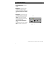
4.0
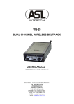
FRONT PANEL CONTROLS
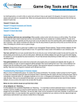
1 VOLUME control knob
This knob adjusts the listen level for the
headset.
2 TALK button
This push button activates the headset
microphone, the bright green LED (5)
indicates if the microphone is switched on.
The beltpack must be in reach of the base
station for the microphone to be switched
on.
3 CALL button
This push button activates the call system.
A momentary push will send a call signal
to all stations connected to the intercom
channel and the call LED (4) will start
flashing.
Press and hold the button for 2 seconds
will activate the call buzzer.
After the CALL button is released the
LED’s will continue to flash for further 2
seconds.
The beltpack must be in reach of the base
station for sending or receiving a CALL
signal.
User Manual WS 19 / Issue 1 © 2002 ASL Intercom, Utrecht, Holland.
4
5.0
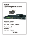
SIDE PANEL CONNECTORS
OWN VOICE trimmer
This trimmer adjusts the level of your own
voice as you hear it in your headset.
The operating area is between fully
clockwise and minimum level. Adjusting this
signal does not affect the level of your voice
as it is heard by other stations.
7 TONE VOLUME
This trimmer adjusts the level of the tones
that the WS 19 produces in case of a low
battery Warning.
8 BUZZER VOLUME trimmer
This trimmer adjusts the volume of the
internal buzzer, which is located behind the
front panel.
The buzzer is activated if you press the
CALL button of the WS 19 (3) or a ALL
button of any other station (on the channel to
which the WS 19 is connected), longer than
2 seconds.
9 MIC GAIN
The mic gain can be adjusted by a trimmer
on the side panel
To increase mic gain turn clockwise.
To decrease mic gain turn
counterclockwise.
User Manual WS 19 / Issue 1 © 2002 ASL Intercom, Utrecht, Holland.
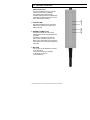
5.0
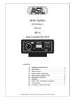
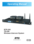
REAR PANEL CONNECTORS
10
Antenna
This small antenna is chosen to be very
flexible and non-removable. For optimum
performance keep the antenna clear from
obstacles.
11
POWER on/off switch
This switch switches the unit on and off.
12
CHANNEL SELECT switch
With this switch the channe l is selected on
which the beltpack will communicate with the
base station. The selected channel must
match the channel set at the base station.
13
DC INPUT connector
Apply a DC voltage of 12 Volts DC to this
connector to charge the internal batteries.
The sleeve is negative and the inner contact
is positive.
The LED indicator (14) will be lit red when
the unit is charging the batteries, and it will
be lit green when the batteries are fully
charged.
15
HEADSET CONNECTOR
An XLR-4 type connector for the connection
of the headset. This must have a can
impedance of 200 ohms (or greater), or
each minimum 400 ohms when in parallel.
The mic may be of the dynamic or electret
type.
Pin assignments:
1. Shield mic. (GND)
2. mic. +
3. phones +
4. phones -
14 Battery charger status LED
This LED indicates the status of the battery
charger. The LED is lit red when the external
adaptor is connected and the batteries are
being charged.
The LED is green lit when the external
adaptor is connected and the batteries are
fully charged.
User Manual WS 19 / Issue 1 © 2002 ASL Intercom, Utrecht, Holland.
6
5.0
SETTING UP A CONNECTION
BASE STATION SETTINGS
SIDETONE ADJUSTMENT
A) The base station must be set up properly
according to the user manual.
Give each TX/RX unit of the base station its
own channel by rotating the Channel select
switch.
Try to avoid concurrent channels to be
physically next to each other, eg. In a setting
of two WS 400’s try to set them in this order :
2, 4, 6, 8, 1, 3, 5, 7
If you use a WS 200 with only two beltpacks
use channels 1 and 6.
Turn down the OWN VOICE volume
trimmer at the side panel of the beltpack.
(clockwise)
Switch on the TALK function of the
beltpack (TALK button).
Talk in the microphone and listen to yur
own voice, you might hear a small delay in
the signal.
Now turn down the volume of your own
voice by adjusting the SIDE TONE
trimmer at the base station of the TX/RX
unit to which the beltpack is connected.
Adjust the trimmer so that the level of your
own voice is as low as possible.
Now turn up the volume of your own voice
by adjusting the OWN VOICE trimmer to
a level that you like.
B) Connect the base station to the partyline
intercom or 4 wire system and make sure
the interface mode switch at the back is set
correctly.
C) turn the sidetone trimmers counter clock
wise.
BELTPACK SETTINGS
FULL DUPLEX AND HALF DUPLEX USE
Select with the channel select switch at the
rear of the beltpack the channel to match the
WS 200 or WS 400 setting.
Connect a headset to the beltpack and
insert fully charged batteries.
When the beltpack is switched on then a
single short tone should be heard and both
led’s on the front panel of the unit will flash
for half a second. This indicates that the
beltpack is functioning okay.
If you press the CALL or TALK button the
led’s on the front panel will be lit and the
corresponding TX/RX unit of the base
station will show a green ACTIVE led.
This means that the beltpack has connection
with the base station.
User Manual WS 19 / Issue 1 © 2002 ASL Intercom, Utrecht, Holland.
Although the system is designed to be
used in full duplex use, there is a
possibility to use the system in half duplex
mode too.
Half duplex allows more than 1 beltpack
on the same frequency and therefore on
one TX/RX unit of a base station.
Every beltpack will be able to listen to the
base station, but only one of the listening
beltpacks can talk at a time and have a
full duplex connection. The other
beltpacks will not be able to CALL or
TALK.
In this mode it is usefull not to adjust the
sidetone trimmer on the base station, turn
it fully counter clockwise.
Read the next chapter about
communication modes carefully.
COMMUNICATION MODES
all of them will receive it.
This system is designed to offer a
maximum of 8 wireless, full duplex,
beltpacks. Each beltpack may be a single
channel beltpack WS 19 or a dual
channel beltpack WS 29.
There is one major drawback to half
duplex mode, this is due to the principle
of the partyline concept.
Each beltpack needs to be assigned to a
unique channel. On this channel the
communication between the beltpack and
the base station will take place. If another
base station is set to the same channel
the communication will be garbled and
will result in a none functioning
connection.
The base station will automatically select
the right mode for a WS 19 or WS 29
beltpack. A WS 19 beltpack will always
be connected to it own channel at the
base station, a WS 29 beltpack will be
assigned to two channels on the base
station.
FULL DUPLEX
A connection of one WS 19 on eg.
Channel 1 will be accomplished by
selecting channel 1 on the beltpack and
channel 1 on TX/RX unit 1 of the base
station. The connection is a dedicated
and full duplex connection.
The sidetone needs to be adjusted at the
front of the base station and the user of
the beltpack can adjust his own voice at
the beltpack with the designated trimmer.
In case of a very good adjusted sidetone
trimmer at the base station this effect will
be noticed :
When 2 or more beltpacks are using the
same TX/RX unit of a base station
(listening to the same signal), and one of
the beltpacks is talking to the base
station, the listening beltpack will not be
able to hear the talking beltpack.
This effect is caused by the adjusted
sidetone that prevents the microphone
signal of a beltpack to be heard by him
self, and therefore also heard by other
beltpacks on the same TX/RX unit.
To solve this the sidetone trimmer of the
TX/RX unit should be turned fully counter
clockwise.
This has one disadvantage too, if a
beltpack talks to the base he will hear his
own voice in his headset with a delay of
24 mS. The other listening beltpacks will
not notice this delay.
By adjusting the OWN VOICE trimmer at
the beltpack the effect can be made less.
HALF DUPLEX
A connection of several WS 19 beltpacks
on eg. Channel 1 to a TX/RX unit of a
base station (also channel 1 selected) is
a half duplex connection.
This means that all the beltpacks can
listen to the same TX/RX unit of the base
station. Only one beltpack can TALK to
the base station. The beltpack that
selects TALK mode will occupy the
connection and the TALK function of all
other listening beltpacks is disabled.
The same for sending CALL signals, only
one beltpack may send a call signal but
User Manual WS 19 / Issue 1 © 2002 ASL Intercom, Utrecht, Holland.
8
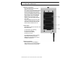
5.0
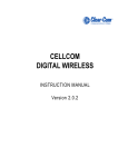
REAR PANEL CONNECTORS
16 Battery compartment
This compartment will hold 6 penlight
batteries of the AA type.
The supplied rechargeable NiMH batteries
are the preferred types for the maximum
duration. Please take special attention in
your choice of batteries, the WS 19 uses a
high discharge current that the batteries
need to sustain over the whole lifespan.
Batteries that can only supply a high
current for a short time will be exhausted
very quickly.
When the batteries reach the end of their
capacity the beltpack will warn you with 4
short tones, the interval of the tones will
shorten when the batteries wear out.
17 Dip switch
This dipswitch controls four functions of the
WS 19, these are:
A
B
C
D
Talk function only momentary
Talk function disabled.
Buzzer function disabled.
Battery save mode.
The dipswitches are turned on by sliding
them towards the side panel of the
beltpack, they are turned off when slid to
the battery compartment.
18 Service connector.
This connector is to be used only for
factory service. Do not connect anything to
it and do not short circuit any of the pins.
User Manual WS 19 / Issue 1 © 2002 ASL Intercom, Utrecht, Holland.
8.0
PARTY LINE, TECHNICAL CONCEPT
ASL's WIRELESS Series offers a complete two way
('full duplex') communications system.
Users of the system are connected via a 'party line'.
base stations (with built-in power supply), beltpacks
and power supplies are interconnected via standard
microphone cable. One wire is used as an audio line,
one as a power line and the screen of the cable
functions as earth/return.
Current drive is used for signal transfer. Each station
utilizes a current amplifier to amplify the microphone
signal and place it on the common audio line where,
due to the constant line impedance (situated in the
power supply between XLR pin 3 and 1), a signal
voltage is developed which can be further amplified
and sent to the headphones.
This principle has three advantages:
- the use of a single audio line allows several
stations to talk and listen simultaneously.
- due to the high bridging impedance offered by
each station, the number of stations 'on line' has
no influence on the level of the communications
signal.
- power and audio to the intercom stations use the
same cable.
The Call signal is also sent as a current on the audio
line. It develops a DC potential over the line
impedance which will be sensed by each station and
interpreted as a Call signal.
9.0
WARRANTY
This unit is warranted by ASL Intercom to the original
end-user purchaser against defects in workmanship
and materials in it's manufacture for a period of one
year from date of shipment to the end-user.
Faults arising from misuse, unauthorized
modifications or accidents are not covered by this
warranty. If the unit is faulty it should be sent in it's
original packing, to the supplier or your local ASL
dealer, with shipping prepaid. A note must be included
stating the faults found and a copy of the original
suppliers invoice.
10.0 TECHNICAL SPECIFICATIONS WS 19
POWER CONSUMPTION
current (at 9 V DC)
200 mA quiescent
280 mA signaling
450 mA at max. output + signaling
MIC. PREAMP
mic. impedance
gain
presence filter
frequency response
V electret mic
200 ohms
40 dB - 70 dB
+6 dB at 5 kHz
200 Hz - 12 kHz (-3 dB)
+9 V DC
HEADPHONES DRIVER AMP
max. load
200 ohms
max. output level
4 V rms (200 ohms)
max. output power
0.16 W rms (each headset can)
BUZZER
max. SPL
90 dBA
DIMENSIONS AND WEIGHT
width
height
depth
weight
88 mm
49 mm
141 mm
650 grams
GENERAL SYSTEM SPECIFICATIONS
dynamic range
Transceiver frequency
Transmit Power
Number of channels
Channel separation
supply voltage
80 dB
2400 – 2483.5 MHz
10 mW E.I.R.P.
8
4.4 MHz
+7,2 V DC (4.2 V to 9 V)
Note : 0dBu = 775 mV into open circuit
ASL reserves the right to alter specifications without
further notice.
THIS PRODUCT WAS DESIGNED, DEVELOPED
AND MANUFACTURED BY:
ASL Intercom
UTRECHT, HOLLAND.
http://www.asl-inter.com
User Manual WS 19 / Issue 1 © 2002 ASL Intercom, Utrecht, Holland.
10