1
CELLCOM
DIGITAL WIRELESS
INSTRUCTION MANUAL
Version 2.0.2
CellCom Instruction Manual
© 2007, 2008, 2009 Vitec Group Communications Ltd. All rights reserved.
Part Number 810335Z Rev. 8
Vitec Group Communications LLC
850 Marina Village Parkway
Alameda, CA 94501
U.S.A
Vitec Group Communications Ltd
7400 Beach Drive
IQ Cambridge
Cambridgeshire
United Kingdom
CB25 9TP
The Vitec Group plc
Beijing Representative Office
Room 706, Tower B
Derun Building, YongAn Dongli A No.3
Jianwai Ave., Chaoyang District
Beijing, P.R.China 100022
® Clear-Com, CellCom/FreeSpeak and the Clear-Com Communication Systems logo are
registered trademarks of The Vitec Group plc
Website: www.clearcom.com
Vitec Group Communications
SOFTWARE LICENSE
IMPORTANT: CAREFULLY READ THE FOLLOWING BEFORE
USING THIS SOFTWARE. USING THE SOFTWARE INDICATES
YOUR ACKNOWLEDGMENT THAT YOU HAVE READ THE
FOLLOWING AND AGREE TO ITS TERMS.
IF YOU DO NOT AGREE, RETURN THE SOFTWARE COMPLETE
TO VITEC GROUP COMMUNICATIONS LIMITED OR CANCEL THE
INSTALLATION.
THIS IS YOUR PROOF THAT YOU HAVE A VALID LICENSE.
PLEASE TREAT IT AS VALUABLE PROPERTY.
VITEC GROUP COMMUNICATIONS LIMITED OR VITEC GROUP
COMMUNICATIONS, INC., as the case may be (hereinafter referred
to as “VGC”), offers you this storage media containing a
computer program and files (the “SOFTWARE”) and offers to
grant to you a non-exclusive and non-transferable License to use
the Software on the following terms. Any new revision or update
of the Software provided by VGC to Customer under this License
shall be governed by the terms and conditions of this License.
1. APPLICATION
a. These terms supersede all prior agreements representations
and understandings between you the Customer and VGC and their
authorised representatives relating to the subject matter hereof
(i.e., the Software) but shall otherwise be subject to Vitec Group
Communications Terms and Conditions, as amended from time to
time. For the avoidance of doubt, in the event of conflict, these
terms shall prevail.
b. No variation to these terms, nor any other terms or conditions
proposed by you, shall be of any effect unless recorded in a written
document signed by VGC. You confirm that any statement made to
the contrary by you or on your behalf shall not apply to this
License.
c. You confirm that you are not relying on any statement made by
or on behalf of VGC, other than statements recorded in a written
document signed by VGC.
d. VGC and its licensors reserve all rights not expressly granted to
you. VGC's licensors are intended third party beneficiaries of this
Agreement and have the express right to rely upon and directly
enforce the terms set forth herein.
e. You agree that the Software belongs to VGC and its licensors.
You agree that you neither own nor hereby acquire any claim or
right of ownership to the Software or to any related patents,
Clear-Com Communication Systems
CellCom V2.0 Instruction Manual
i
copyrights, trademarks or other intellectual property. VGC and its
licensors retain all right, title and interest in and to the Software and
all copies thereof at all times, regardless of the form or media in or
on which the original or other copies may subsequently exist. This
license is not a sale of the original or any subsequent copy.
2. COPYRIGHT
a. The copyright and all other rights in the Software produced by
VGC shall remain with VGC or its suppliers. You must reproduce
any copyright or other notice marked on the Software on any
copies that you make.
3. YOU MAY:
a. Use the Software only at a single site location. If you wish to use
the Software at more than one site you must contact VGC and if
required purchase further Licenses;
b. Make one copy of the Software for archival or back-up purposes,
and;
c. Transfer the Software to an end user of a VGC product, only if
you have made it clear to VGC that you are not the end user and
you assign all of your rights under this License and make no use of
the Software yourself.
4. YOU MAY NOT:
a. Use the Software or make copies of it except as permitted in this
License;
b. Publish or distribute the computer images, sound files or fonts
included with the Software as computer images, sound files or
fonts;
c. Translate, reverse engineer, decompile or disassemble the
Software, except to the extent the foregoing restriction is expressly
prohibited by applicable law;
d. Rent, lease, assign or transfer the Software except as set out
above; or
e. Modify the Software or merge all or any part of the Software in
another program.
5. TERM:
a. This License shall continue for as long as you use the Software.
However, it will terminate if you fail to comply with any of its terms
or conditions. You agree, upon termination, to destroy all copies of
the Software. The Limitations of Warranties and Liability set out
below shall continue in force even after any termination.
6. LIMITED WARRANTY:
a. VGC warrants that the storage media in this Software will be free
from defects in materials and workmanship for 90 days from the
date you acquire it. If such a defect occurs, return it to us at the
address below and we will replace it free. This remedy is your
exclusive remedy for breach of this warranty.
ii
Clear-Com Communication Systems
CellCom V2.0 Instruction Manual
b. After the initial 90 days, THE SOFTWARE IS PROVIDED "AS
IS" WITHOUT WARRANTY OF ANY KIND EITHER EXPRESS,
IMPLIED OR STATUTORY, INCLUDING BUT NOT LIMITED TO
THE IMPLIED WARRANTIES OF MERCHANTABILITY, FITNESS
FOR A PARTICULAR PURPOSE, PERFORMANCE, ACCURACY,
RELIABILITY, OR NON-INFRINGEMENT OF THIRD-PARTY
INTELLECTUAL PROPERTY RIGHTS. This constitutes an
essential part of this License.
7. LIMITATION OF LIABILITY:
a. For the avoidance of doubt, all conditions imposed by law
covering matters such as fitness for purpose, compliance to
description, negligence and quality are expressly excluded from
this agreement and you agree to accept the foregoing warranty in
lieu of all such items.
b. IN NO EVENT SHALL VGC BE LIABLE FOR ANY LOSS OF
PROFITS, LOSS OF BUSINESS, LOSS OF DATA OR USE OF
DATA, INTERRUPTION OF BUSINESS, OR FOR INDIRECT,
SPECIAL, INCIDENTAL, EXEMPLARY, MULTIPLE, PUNITIVE OR
CONSEQUENTIAL DAMAGES OF ANY KIND, WHETHER
BASED ON CONTRACT, TORT (INCLUDING WITHOUT
LIMITATION, NEGLIGENCE), WARRANTY, GUARANTEE OR
ANY OTHER LEGAL OR EQUITABLE GROUNDS, EVEN IF VGC
HAS BEEN ADVISED OF THE POSSIBILITY OF SUCH
DAMAGES.
c. The warranty is personal to you (or end user if you have made it
clear that you are not the end user) and may not be transferred
(except as permitted expressly above).
d. VGC shall not be a liable for failure to perform any obligation to
you where such failure is due to circumstances beyond VGC’s
reasonable control.
e. VGC offers extended warranties and, if you are not satisfied
with the above, you should consider such warranties or
consider separate insurance.
8. RESTRICTED RIGHTS:
If this Software is acquired by or for the U.S. Government then it is provided with Restricted Rights. Use, duplication, or disclosure by the U.S.
Government is subject to restrictions as set forth in subparagraph
(c)(1)(ii) of The Rights in Technical Data and Computer Software clause
at DFARS 252.227-7013, or subparagraphs (c)(1) and (2) of the Commercial Computer Software - Restricted Rights at 48 CFR 52.227-19, or
clause 18-52.227-86(d) of the NASA Supplement to the FAR, as applicable. Contractor/manufacturer: Vitec Group Communications Limited,
7400 Beach Drive, Cambridge, England CB25 9TP or Vitec Group
Communications, LLC, 850 Marina Village Parkway, Alameda, CA
94501.
9. OTHER ISSUES:
a. Any failure by VGC to insist on its strict rights under this
Agreement shall not be deemed to be a waiver of those (or any
Clear-Com Communication Systems
CellCom V2.0 Instruction Manual
iii
other rights) and only a duly executed written release shall
constitute such a waiver.
b. If any of these conditions is deemed invalid or unenforceable the
remainder shall be unaffected.
c. VGC's dealings with you shall be governed by English law if you
are resident in the EMEA region and California law if you are
resident elsewhere. The federal and state courts of California for
Non-EMEA Customers and English Courts for EMEA Customers
shall have exclusive jurisdiction to adjudicate any dispute arising
out of this Agreement.
d. If any document is written in more than one language the
English text shall prevail.
e. Capitalized terms not defined herein shall have the meanings
set forth in Vitec Group Communications' Terms and Conditions, as
amended from time to time.
iv
Clear-Com Communication Systems
CellCom V2.0 Instruction Manual
CONTENTS
GETTING STARTED: AN INTRODUCTION TO
CELLCOM . . . . . . . . . . . . . . . . . . . . . . . . . . . . . . . . 1-1
CellCom Features. . . . . . . . . . . . . . . . . . . . . . . . . . . . . . . . . . . . . . . 1-2
A CellCom Communication System . . . . . . . . . . . . . . . . . . . . . . . . . 1-3
Important Installation Information . . . . . . . . . . . . . . . . . . . . . . . . . 1-5
System Password . . . . . . . . . . . . . . . . . . . . . . . . . . . . . . . . . . . 1-5
Default Map . . . . . . . . . . . . . . . . . . . . . . . . . . . . . . . . . . . . . . . . 1-5
QUICK START . . . . . . . . . . . . . . . . . . . . . . . . . . . . . 2-1
Connecting the Basestation . . . . . . . . . . . . . . . . . . . . . . . . . . . . . . . 2-1
Overview of Beltpack Operation . . . . . . . . . . . . . . . . . . . . . . . . . . . . 2-4
Assigning Labels to the CellCom BeltPacks. . . . . . . . . . . . . . . . . . . 2-4
Creating a Group . . . . . . . . . . . . . . . . . . . . . . . . . . . . . . . . . . . . . . . 2-5
Assigning the Group Label to CellCom Beltpack Keys . . . . . . . . . . . 2-5
Calling the Group from the Beltpacks . . . . . . . . . . . . . . . . . . . . . . . . 2-6
Calling the Group from the 4-Wire Audio Device . . . . . . . . . . . . . . . 2-7
Calling the Group from the Wired Party-Line Beltpack . . . . . . . . . . . 2-7
Creating a Wireless Party Line . . . . . . . . . . . . . . . . . . . . . . . . . . . . . 2-8
Assigning the Wireless Party Line Label to CellCom Beltpack Keys 2-8
Calling the Wireless Party Line from the Beltpacks . . . . . . . . . . . . . 2-9
Calling the Wireless Party Line from the 4-Wire Audio Device. . . . 2-10
Calling the Wireless Party Line from the Wired Party-Line Beltpack . .
2-11
OPERATING THE CELLCOM BASESTATION . . . . 3-1
Introduction . . . . . . . . . . . . . . . . . . . . . . . . . . . . . . . . . . . . . . . . . . . . 3-1
Understanding Front-Panel Operation . . . . . . . . . . . . . . . . . . . . . . . 3-2
Headset Connector . . . . . . . . . . . . . . . . . . . . . . . . . . . . . . . . . . 3-2
& Channel A Talk Switch and Light/Listen Level Knob . . . . . . 3-2
A/B Reply Button . . . . . . . . . . . . . . . . . . . . . . . . . . . . . . . . . . . 3-3
& Channel B Talk Switch and Light/Listen Level Knob . . . . . . 3-3
Party Line Channels A and B Enable Switches . . . . . . . . . . . . . 3-3
Program Audio Enable Switch and Light . . . . . . . . . . . . . . . . . . 3-3
Antenna Light Display . . . . . . . . . . . . . . . . . . . . . . . . . . . . . . . . 3-3
Display Screen. . . . . . . . . . . . . . . . . . . . . . . . . . . . . . . . . . . . . . 3-4
Power Switch . . . . . . . . . . . . . . . . . . . . . . . . . . . . . . . . . . . . . . . 3-4
Clear-Com Communication Systems
CellCom V2.0 Instruction Manual
i
CONNECTING THE CELLCOM BASESTATION . . 4-1
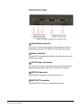
Understanding the Back-Panel Connectors . . . . . . . . . . . . . . . . . . . 4-1
IEC Power Connector . . . . . . . . . . . . . . . . . . . . . . . . . . . . . . . . 4-2
Party Line Channel A Connectors . . . . . . . . . . . . . . . . . . . . . . . 4-2
Party Line Channel B Connectors . . . . . . . . . . . . . . . . . . . . . . . 4-2
Program Input Connector . . . . . . . . . . . . . . . . . . . . . . . . . . . . . 4-2
Stage Announce Output Connector. . . . . . . . . . . . . . . . . . . . . . 4-2
Stage Announce Relay . . . . . . . . . . . . . . . . . . . . . . . . . . . . . . . 4-3
4-Wire Matrix Ports . . . . . . . . . . . . . . . . . . . . . . . . . . . . . . . . . . 4-3
Base Loop Connector (not used). . . . . . . . . . . . . . . . . . . . . . . . 4-3
LAN Connector . . . . . . . . . . . . . . . . . . . . . . . . . . . . . . . . . . . . . 4-3
PC Connector . . . . . . . . . . . . . . . . . . . . . . . . . . . . . . . . . . . . . . 4-3
Transceiver Connectors. . . . . . . . . . . . . . . . . . . . . . . . . . . . . . . 4-3
Connecting to Party-Line Intercom Systems . . . . . . . . . . . . . . . . . . 4-4
Clear-Com and Compatible Party-Line . . . . . . . . . . . . . . . . . . . . . 4-4
Connecting Directly to Clear-Com Party-Line Beltpacks. . . . . . . . 4-5
Connecting to an RTS™ Wired Beltpack . . . . . . . . . . . . . . . . . . . 4-6
Front-Panel Adjustments for Party-Line Connections . . . . . . . . . . 4-6
Troubleshooting Party-Line Connections . . . . . . . . . . . . . . . . . . . 4-8
Reducing CellCom Beltpack echo when talking to a analogue party-line . . . . . . . . . . . . . . . . . . . . . . . . . . . . . . . . . . . . . . . . . . . . . . . . 4-8
How to set the microphone gain in the beltpack . . . . . . . . . . . 4-8
Include the Party-Line channel inside a Wireless Party-Line group
4-8
How to set the VOX gating level on the Party-Line connected to
the Basestation . . . . . . . . . . . . . . . . . . . . . . . . . . . . . . . . . . . . . . . . . 4-8
Auto null the Party-Line channel at the Basestation . . . . . . . . 4-9
Wireless Party-Line. . . . . . . . . . . . . . . . . . . . . . . . . . . . . . . . . . . . . 4-10
Connecting to 4-Wire and Digital Matrix Intercom . . . . . . . . . . . . . 4-10
Connecting to Clear-Com Matrix Plus 3 . . . . . . . . . . . . . . . . . . . 4-12
Connecting to Clear-Com Eclipse Digital Matrix . . . . . . . . . . . . . 4-12
Connecting with Other Digital Matrix Intercom Systems . . . . . . . 4-13
Connecting with Other 4-Wire Devices . . . . . . . . . . . . . . . . . . . . 4-14
Connecting to a Program Audio Source . . . . . . . . . . . . . . . . . . . . . 4-14
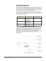
IFB Configuration . . . . . . . . . . . . . . . . . . . . . . . . . . . . . . . . . . . . . . 4-15
Connecting to the Stage Announce Output . . . . . . . . . . . . . . . . . . 4-16
Connecting to a PC. . . . . . . . . . . . . . . . . . . . . . . . . . . . . . . . . . . . . 4-17
Connecting Via the Serial Port . . . . . . . . . . . . . . . . . . . . . . . . . . 4-17
Connecting Via the LAN Port . . . . . . . . . . . . . . . . . . . . . . . . . . . 4-18
Connecting to Transceiver/Antennas (CEL-TA) . . . . . . . . . . . . . . . 4-18
ii
Clear-Com Communication Systems
CellCom V2.0 Instruction Manual
Connecting One Transceiver/Antenna (CEL-TA) Directly to A Transceiver Port. . . . . . . . . . . . . . . . . . . . . . . . . . . . . . . . . . . . . . . . . . . . 4-18
Connecting Transceiver/Antennas with a Splitter (PD2203) . . . . 4-19
Powering an Antenna or Antenna Splitter . . . . . . . . . . . . . . . . . . 4-20
PROGRAMMING A SYSTEM FROM THE BASESTATION . . . . . . . . . . . . . . . . . . . . . . . . . . . . . . . . . . . . 5-1
A Note About Terminology . . . . . . . . . . . . . . . . . . . . . . . . . . . . . . . . 5-2
Using the Basestation’s Programming Menus . . . . . . . . . . . . . . . . . 5-2
Saving Changes . . . . . . . . . . . . . . . . . . . . . . . . . . . . . . . . . . . . . . . . 5-2
Basestation Password . . . . . . . . . . . . . . . . . . . . . . . . . . . . . . . . . . . 5-2
Changing Beltpack Labels . . . . . . . . . . . . . . . . . . . . . . . . . . . . . . . . 5-4
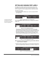
Setting and Changing Port Labels . . . . . . . . . . . . . . . . . . . . . . . . . . 5-6
Setting and Changing Group Labels. . . . . . . . . . . . . . . . . . . . . . . . . 5-7
Adding Group Members . . . . . . . . . . . . . . . . . . . . . . . . . . . . . . . . . 5-10
Beltpacks . . . . . . . . . . . . . . . . . . . . . . . . . . . . . . . . . . . . . . . . . . . . 5-11
Assigning Labels to Beltpacks Keys . . . . . . . . . . . . . . . . . . . . . . 5-11
Setting the Beltpack Audio Level. . . . . . . . . . . . . . . . . . . . . . . . . 5-14
Setting Beltpack Latching . . . . . . . . . . . . . . . . . . . . . . . . . . . . . . 5-14
Setting Beltpack Groups . . . . . . . . . . . . . . . . . . . . . . . . . . . . . . . 5-15
Setting Beltpack Labels. . . . . . . . . . . . . . . . . . . . . . . . . . . . . . . . 5-16
Registering a Beltpack . . . . . . . . . . . . . . . . . . . . . . . . . . . . . . . . 5-16
Setting Input and Output Port Levels . . . . . . . . . . . . . . . . . . . . . . . 5-17
Setting Port Call Destination . . . . . . . . . . . . . . . . . . . . . . . . . . . . 5-19
Configuring a Party Line . . . . . . . . . . . . . . . . . . . . . . . . . . . . . . . . . 5-22
Basestation SYSTEM Menu . . . . . . . . . . . . . . . . . . . . . . . . . . . . . . 5-26
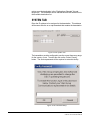
System INFO (“INFO”) . . . . . . . . . . . . . . . . . . . . . . . . . . . . . . . . 5-27
Restoring the Defaults (“DEFAULT”) . . . . . . . . . . . . . . . . . . . . . . 5-27
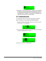
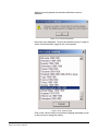
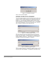
ANTENNAS (“ANTENNAS”) . . . . . . . . . . . . . . . . . . . . . . . . . . . . 5-27
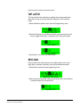
Setting the IP Address (“IP”) . . . . . . . . . . . . . . . . . . . . . . . . . . . . 5-28
Locking Front-Panel Enable Buttons (“Lock”) . . . . . . . . . . . . . . . 5-28
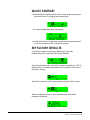
Remote Microphone Kill (“RMK”) . . . . . . . . . . . . . . . . . . . . . . . . 5-29
Kill Beltpack Microphones (“KILL(BP”) . . . . . . . . . . . . . . . . . . 5-29
Kill Party Line Microphones (“KILL(PL)”) . . . . . . . . . . . . . . . . . 5-29
Kill All Microphones (“KILL(ALL)”) . . . . . . . . . . . . . . . . . . . . . . 5-29
Battery Indicator (“BATTERY”) . . . . . . . . . . . . . . . . . . . . . . . . . . 5-30
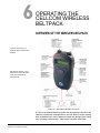
OPERATING THE CELLCOM WIRELESS BELTPACK
6-1
Overview of the Wireless Belpack . . . . . . . . . . . . . . . . . . . . . . . . . . 6-1
Clear-Com Communication Systems
CellCom V2.0 Instruction Manual
iii
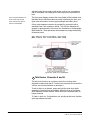
Beltpack Top Control Section . . . . . . . . . . . . . . . . . . . . . . . . . . . . 6-2
Talk Knobs, Channels A and B . . . . . . . . . . . . . . . . . . . . . . . . . 6-2
Level-Control Lights, Channels A and B . . . . . . . . . . . . . . . . . . 6-3
Talk/Listen Lights, Channels A and B . . . . . . . . . . . . . . . . . . . . 6-3
Answer-Back Lights . . . . . . . . . . . . . . . . . . . . . . . . . . . . . . . . . . 6-3
Combo Button . . . . . . . . . . . . . . . . . . . . . . . . . . . . . . . . . . . . . . 6-3
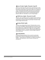
Beltpack Front/Display Section . . . . . . . . . . . . . . . . . . . . . . . . . . . 6-4
Backlit LCD Display . . . . . . . . . . . . . . . . . . . . . . . . . . . . . . . . . . 6-4
Left and Right Scroll Buttons . . . . . . . . . . . . . . . . . . . . . . . . . . . 6-4
Enter/Answer-Back Button. . . . . . . . . . . . . . . . . . . . . . . . . . . . . 6-4
Beltpack Batteries. . . . . . . . . . . . . . . . . . . . . . . . . . . . . . . . . . . . . . . 6-5
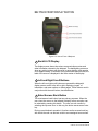
Beltpack Rear/Battery Section . . . . . . . . . . . . . . . . . . . . . . . . . . . 6-5
Power Button . . . . . . . . . . . . . . . . . . . . . . . . . . . . . . . . . . . . . . . 6-5
Battery Case . . . . . . . . . . . . . . . . . . . . . . . . . . . . . . . . . . . . . . . 6-5
Belt Clip . . . . . . . . . . . . . . . . . . . . . . . . . . . . . . . . . . . . . . . . . . . 6-6
Beltpack Bottom Connector Section . . . . . . . . . . . . . . . . . . . . . . . 6-6
Data Connector . . . . . . . . . . . . . . . . . . . . . . . . . . . . . . . . . . . . . 6-6
Headset Connector . . . . . . . . . . . . . . . . . . . . . . . . . . . . . . . . . . 6-6
Battery Recharger Connector . . . . . . . . . . . . . . . . . . . . . . . . . . 6-7
Beltpack Turn-On Sequence . . . . . . . . . . . . . . . . . . . . . . . . . . . . . 6-7
Beltpack Turn-Off Sequence . . . . . . . . . . . . . . . . . . . . . . . . . . . . . 6-7
Powering the CellCom Beltpack . . . . . . . . . . . . . . . . . . . . . . . . . . 6-7
Registering Beltpacks with the Basestation . . . . . . . . . . . . . . . . . 6-9
Removing Registered Beltpacks from the Basestation . . . . . . . . 6-10
Accessing the Talk/Listen Paths on the CellCom Beltpack. . . . . . . 6-10
Setting and Adjusting Listen Levels . . . . . . . . . . . . . . . . . . . . . . 6-11
Headset Limiter . . . . . . . . . . . . . . . . . . . . . . . . . . . . . . . . . . . . . . 6-12
Using the Beltpack Answer-Back Functions . . . . . . . . . . . . . . . . 6-12
Beltpack Menu Options. . . . . . . . . . . . . . . . . . . . . . . . . . . . . . . . . . 6-13
Alarm Options . . . . . . . . . . . . . . . . . . . . . . . . . . . . . . . . . . . . . . . 6-13
Low Battery Alarm . . . . . . . . . . . . . . . . . . . . . . . . . . . . . . . . . . 6-13
Low Signal Alarm. . . . . . . . . . . . . . . . . . . . . . . . . . . . . . . . . . . 6-13
Audio Options . . . . . . . . . . . . . . . . . . . . . . . . . . . . . . . . . . . . . . . 6-14
Headphone-Off Level Option . . . . . . . . . . . . . . . . . . . . . . . . . . 6-14
Page Lock Option . . . . . . . . . . . . . . . . . . . . . . . . . . . . . . . . . . 6-14
Headphone Limiter Option. . . . . . . . . . . . . . . . . . . . . . . . . . . . 6-14
Microphone Type Option . . . . . . . . . . . . . . . . . . . . . . . . . . . . . 6-14
Microphone Level Option. . . . . . . . . . . . . . . . . . . . . . . . . . . . . 6-15
Headset Options . . . . . . . . . . . . . . . . . . . . . . . . . . . . . . . . . . . 6-15
View Status . . . . . . . . . . . . . . . . . . . . . . . . . . . . . . . . . . . . . . . . . 6-15
iv
Clear-Com Communication Systems
CellCom V2.0 Instruction Manual
Role Information . . . . . . . . . . . . . . . . . . . . . . . . . . . . . . . . . . . 6-15
Beltpack Version . . . . . . . . . . . . . . . . . . . . . . . . . . . . . . . . . . . 6-15
Beltpack ID . . . . . . . . . . . . . . . . . . . . . . . . . . . . . . . . . . . . . . . 6-15
RF Carrier Mask . . . . . . . . . . . . . . . . . . . . . . . . . . . . . . . . . . . 6-15
Connection Info . . . . . . . . . . . . . . . . . . . . . . . . . . . . . . . . . . . . 6-16
Adjust Contrast . . . . . . . . . . . . . . . . . . . . . . . . . . . . . . . . . . . . 6-16
PROGRAMMING AT THE BELTPACK . . . . . . . . . . 7-1
Introduction to Programming on the Beltpack. . . . . . . . . . . . . . . . . . 7-1
Beltpack Programming - Menu Structure . . . . . . . . . . . . . . . . . . . . . 7-1
Main Programming Menu . . . . . . . . . . . . . . . . . . . . . . . . . . . . . . . . . 7-2
The Alarm Options Menu . . . . . . . . . . . . . . . . . . . . . . . . . . . . . . . . . 7-3
Switching the Low Battery Alarm ON and OFF . . . . . . . . . . . . . . . 7-4
Low Battery Alarm Off . . . . . . . . . . . . . . . . . . . . . . . . . . . . . . . . 7-4
Low Battery Alarm On1 . . . . . . . . . . . . . . . . . . . . . . . . . . . . . . . 7-4
Low Battery Alarm On2 . . . . . . . . . . . . . . . . . . . . . . . . . . . . . . . 7-4
Low Battery Alarm Threshold . . . . . . . . . . . . . . . . . . . . . . . . . . 7-5
Low Battery Threshold Setup . . . . . . . . . . . . . . . . . . . . . . . . . . 7-5
Switching the Low Signal Strength Alarm ON and OFF . . . . . . . . 7-5
The Vibra Call Alert Menu . . . . . . . . . . . . . . . . . . . . . . . . . . . . . . . 7-5
The Headphone Menu . . . . . . . . . . . . . . . . . . . . . . . . . . . . . . . . . . . 7-6
Headset Noise Gate . . . . . . . . . . . . . . . . . . . . . . . . . . . . . . . . . . . 7-9
The Microphone Menu . . . . . . . . . . . . . . . . . . . . . . . . . . . . . . . . . . . 7-9
The Status (Information) Menu . . . . . . . . . . . . . . . . . . . . . . . . . . . . 7-10
Adjust Contrast . . . . . . . . . . . . . . . . . . . . . . . . . . . . . . . . . . . . . . . . 7-14
Set Factory Defaults . . . . . . . . . . . . . . . . . . . . . . . . . . . . . . . . . . . . 7-14
Tap Latch . . . . . . . . . . . . . . . . . . . . . . . . . . . . . . . . . . . . . . . . . . . . 7-15
Keylock . . . . . . . . . . . . . . . . . . . . . . . . . . . . . . . . . . . . . . . . . . . . . . 7-15
PTT Configuration. . . . . . . . . . . . . . . . . . . . . . . . . . . . . . . . . . . . . . 7-16
Master Volume Control . . . . . . . . . . . . . . . . . . . . . . . . . . . . . . . . . . 7-17
Page Options . . . . . . . . . . . . . . . . . . . . . . . . . . . . . . . . . . . . . . . . . 7-18
Page Locking . . . . . . . . . . . . . . . . . . . . . . . . . . . . . . . . . . . . . . . 7-18
OPERATING THE CELLCOM TRANSCEIVER/
ANTENNA . . . . . . . . . . . . . . . . . . . . . . . . . . . . . . . . 8-1
Transceiver/Antenna (CEL-TA). . . . . . . . . . . . . . . . . . . . . . . . . . . . . 8-1
CEL-TA Top Panel. . . . . . . . . . . . . . . . . . . . . . . . . . . . . . . . . . . . . 8-1
Omnidirectional Antennas . . . . . . . . . . . . . . . . . . . . . . . . . . . . . 8-1
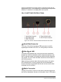
CEL-TA Bottom/Control Panel. . . . . . . . . . . . . . . . . . . . . . . . . . . . 8-2
Serial Data Connector . . . . . . . . . . . . . . . . . . . . . . . . . . . . . . . . 8-2
Data Signal LED . . . . . . . . . . . . . . . . . . . . . . . . . . . . . . . . . . . . 8-2
Clear-Com Communication Systems
CellCom V2.0 Instruction Manual
v
Matrix Connector . . . . . . . . . . . . . . . . . . . . . . . . . . . . . . . . . . . . 8-2
Power LED. . . . . . . . . . . . . . . . . . . . . . . . . . . . . . . . . . . . . . . . . 8-3
DC In Power Connector. . . . . . . . . . . . . . . . . . . . . . . . . . . . . . . 8-3
Cabling the CEL-TA Transceiver/Antennas. . . . . . . . . . . . . . . . . . 8-3
Beltpack Support Capacities for Transceiver/Antennas . . . . . . . . 8-3
Coverage Areas Under Various Conditions. . . . . . . . . . . . . . . . . . 8-4
Transceiver/Antenna Setup Rules and Tips . . . . . . . . . . . . . . . . . 8-4
Transceiver/Antenna Splitter (PD2203) . . . . . . . . . . . . . . . . . . . . . . 8-5
PD2203 Front Connector Panel . . . . . . . . . . . . . . . . . . . . . . . . . . 8-6
Basestation Connection Indicator Light . . . . . . . . . . . . . . . . . . . 8-6
Matrix (CellCom Basestation) Connector . . . . . . . . . . . . . . . . . 8-6
Splitter-to-Transceiver/Antenna Signal Indicator Light . . . . . . . 8-6
Transceiver/Antenna Connectors . . . . . . . . . . . . . . . . . . . . . . . 8-6
PD2203 Rear Panel . . . . . . . . . . . . . . . . . . . . . . . . . . . . . . . . . . . 8-7
Serial Data Connector . . . . . . . . . . . . . . . . . . . . . . . . . . . . . . . . 8-7
Power Indicator . . . . . . . . . . . . . . . . . . . . . . . . . . . . . . . . . . . . . 8-7
DC IN Power Connector . . . . . . . . . . . . . . . . . . . . . . . . . . . . . . 8-7
EXP IN Connector . . . . . . . . . . . . . . . . . . . . . . . . . . . . . . . . . . . 8-7
EXP OUT Connector . . . . . . . . . . . . . . . . . . . . . . . . . . . . . . . . . 8-7
Connecting an Antenna Splitter to the CellCom Basestation and to
Transceiver/Antennas . . . . . . . . . . . . . . . . . . . . . . . . . . . . . . . . . . . . 8-8
INSTALLING A SYSTEM. . . . . . . . . . . . . . . . . . . . . 9-1
Placing the Basestation . . . . . . . . . . . . . . . . . . . . . . . . . . . . . . . . . . 9-1
Placing the Antennas and Splitters . . . . . . . . . . . . . . . . . . . . . . . . . . 9-1
Wiring the Antennas and Splitters . . . . . . . . . . . . . . . . . . . . . . . . . 9-1
Determining Coverage Areas . . . . . . . . . . . . . . . . . . . . . . . . . . . . 9-2
Doing a Site Survey to Determine Coverage Areas . . . . . . . . . . . . . 9-3
Testing Coverage Areas of Individual Antennas . . . . . . . . . . . . . . 9-3
Testing Antenna Handoff . . . . . . . . . . . . . . . . . . . . . . . . . . . . . . . . 9-5
Getting Information on Active Antenna Status . . . . . . . . . . . . . . . 9-6
Assigning Beltpacks to Coverage Areas . . . . . . . . . . . . . . . . . . . . 9-7
Conditions Affecting Coverage Areas . . . . . . . . . . . . . . . . . . . . . . 9-7
CELLCOM CONFIGURATION EDITOR . . . . . . . . 10-1
Introduction . . . . . . . . . . . . . . . . . . . . . . . . . . . . . . . . . . . . . . . . . . 10-1
Loading and Saving Configurations . . . . . . . . . . . . . . . . . . . . . . . . 10-1
Loading a configuration from disk . . . . . . . . . . . . . . . . . . . . . . . . 10-2
COM port selection . . . . . . . . . . . . . . . . . . . . . . . . . . . . . . . . . . . 10-2
IP Setup . . . . . . . . . . . . . . . . . . . . . . . . . . . . . . . . . . . . . . . . . . . 10-2
vi
Clear-Com Communication Systems
CellCom V2.0 Instruction Manual
Retrieving a configuration from a Cellcom basestation via the Serial
Link . . . . . . . . . . . . . . . . . . . . . . . . . . . . . . . . . . . . . . . . . . . . . . . . . 10-2
Retrieving a configuration from a Cellcom basestation via Ethernet.
10-4
Help . . . . . . . . . . . . . . . . . . . . . . . . . . . . . . . . . . . . . . . . . . . . . 10-5
Clear Map . . . . . . . . . . . . . . . . . . . . . . . . . . . . . . . . . . . . . . . . 10-5
Send File . . . . . . . . . . . . . . . . . . . . . . . . . . . . . . . . . . . . . . . . . 10-5
Exit. . . . . . . . . . . . . . . . . . . . . . . . . . . . . . . . . . . . . . . . . . . . . . 10-5
Uploading configurations Using the Serial Link. . . . . . . . . . . . . . 10-6
Uploading configurations Using Ethernet . . . . . . . . . . . . . . . . . . 10-6
Beltpacks tab . . . . . . . . . . . . . . . . . . . . . . . . . . . . . . . . . . . . . . . . . 10-7
Selecting the beltpack to register or edit . . . . . . . . . . . . . . . . . . . 10-7
Registering beltpacks Using the Serial Link . . . . . . . . . . . . . . . . 10-8
The Overview button . . . . . . . . . . . . . . . . . . . . . . . . . . . . . . . . . . 10-9
The Set Defaults Button . . . . . . . . . . . . . . . . . . . . . . . . . . . . . . . 10-9
Read Beltpack Settings . . . . . . . . . . . . . . . . . . . . . . . . . . . . . 10-10
Write Beltpack Settings . . . . . . . . . . . . . . . . . . . . . . . . . . . . . 10-10
Remember My Default Settings. . . . . . . . . . . . . . . . . . . . . . . 10-10
Recall My Default Settings. . . . . . . . . . . . . . . . . . . . . . . . . . . 10-10
Recall Factory Defaults . . . . . . . . . . . . . . . . . . . . . . . . . . . . . 10-11
Headset Limiter . . . . . . . . . . . . . . . . . . . . . . . . . . . . . . . . . . . 10-11
MIC Type . . . . . . . . . . . . . . . . . . . . . . . . . . . . . . . . . . . . . . . . 10-11
MIC Gain Level . . . . . . . . . . . . . . . . . . . . . . . . . . . . . . . . . . . 10-11
MIC Noisegate Level . . . . . . . . . . . . . . . . . . . . . . . . . . . . . . . 10-11
Headphone Off Level. . . . . . . . . . . . . . . . . . . . . . . . . . . . . . . 10-11
Sidetone Level . . . . . . . . . . . . . . . . . . . . . . . . . . . . . . . . . . . . 10-11
Master Volume. . . . . . . . . . . . . . . . . . . . . . . . . . . . . . . . . . . . 10-11
Menu Level . . . . . . . . . . . . . . . . . . . . . . . . . . . . . . . . . . . . . . 10-12
Page Change. . . . . . . . . . . . . . . . . . . . . . . . . . . . . . . . . . . . . 10-12
Keytap Mode . . . . . . . . . . . . . . . . . . . . . . . . . . . . . . . . . . . . . 10-12
RSSI Warning . . . . . . . . . . . . . . . . . . . . . . . . . . . . . . . . . . . . 10-12
Low Battery Warning . . . . . . . . . . . . . . . . . . . . . . . . . . . . . . . 10-12
Keylock . . . . . . . . . . . . . . . . . . . . . . . . . . . . . . . . . . . . . . . . . 10-13
Call Alert . . . . . . . . . . . . . . . . . . . . . . . . . . . . . . . . . . . . . . . . 10-13
Assigning beltpack keys . . . . . . . . . . . . . . . . . . . . . . . . . . . . . . 10-13
The Reply key . . . . . . . . . . . . . . . . . . . . . . . . . . . . . . . . . . . . . . 10-14
Key assignment types . . . . . . . . . . . . . . . . . . . . . . . . . . . . . . . . 10-15
Latching keys. . . . . . . . . . . . . . . . . . . . . . . . . . . . . . . . . . . . . 10-15
On Page Change Cut . . . . . . . . . . . . . . . . . . . . . . . . . . . . . . 10-16
Menu . . . . . . . . . . . . . . . . . . . . . . . . . . . . . . . . . . . . . . . . . . . 10-16
Clear-Com Communication Systems
CellCom V2.0 Instruction Manual
vii
Advanced Menu Setting . . . . . . . . . . . . . . . . . . . . . . . . . . . 10-16
Normal Menu Setting . . . . . . . . . . . . . . . . . . . . . . . . . . . . . 10-16
Basic Menu Setting. . . . . . . . . . . . . . . . . . . . . . . . . . . . . . . 10-16
None Menu Setting . . . . . . . . . . . . . . . . . . . . . . . . . . . . . . . 10-16
Input and output levels . . . . . . . . . . . . . . . . . . . . . . . . . . . . . . . 10-16
Ports tab . . . . . . . . . . . . . . . . . . . . . . . . . . . . . . . . . . . . . . . . . . . 10-17
Selecting the port to edit . . . . . . . . . . . . . . . . . . . . . . . . . . . . . . 10-17
Changing the label of the port . . . . . . . . . . . . . . . . . . . . . . . . . . 10-18
Type drop-down box . . . . . . . . . . . . . . . . . . . . . . . . . . . . . . . . . 10-18
Cross Point assignment drop-down box . . . . . . . . . . . . . . . . . . 10-18
Input and output levels . . . . . . . . . . . . . . . . . . . . . . . . . . . . . . . 10-19
Groups tab . . . . . . . . . . . . . . . . . . . . . . . . . . . . . . . . . . . . . . . . . . 10-20
Selecting the group to edit . . . . . . . . . . . . . . . . . . . . . . . . . . . . 10-20
Changing the label of the group . . . . . . . . . . . . . . . . . . . . . . . . 10-20
Changing the members of the group. . . . . . . . . . . . . . . . . . . . . 10-20
Group Overview . . . . . . . . . . . . . . . . . . . . . . . . . . . . . . . . . . . . 10-21
Antennas tab . . . . . . . . . . . . . . . . . . . . . . . . . . . . . . . . . . . . . . . . 10-21
IFB Tab . . . . . . . . . . . . . . . . . . . . . . . . . . . . . . . . . . . . . . . . . . . . . 10-22
Configuring an IFB . . . . . . . . . . . . . . . . . . . . . . . . . . . . . . . . . . 10-22
System Tab . . . . . . . . . . . . . . . . . . . . . . . . . . . . . . . . . . . . . . . . . . 10-24
DECT carriers . . . . . . . . . . . . . . . . . . . . . . . . . . . . . . . . . . . . . . 10-26
Sys ID . . . . . . . . . . . . . . . . . . . . . . . . . . . . . . . . . . . . . . . . . . . . 10-26
System Number . . . . . . . . . . . . . . . . . . . . . . . . . . . . . . . . . . . . 10-26
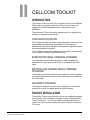
CELLCOM TOOLKIT . . . . . . . . . . . . . . . . . . . . . . . 11-1
Introduction . . . . . . . . . . . . . . . . . . . . . . . . . . . . . . . . . . . . . . . . . . 11-1
Configuration Editor . . . . . . . . . . . . . . . . . . . . . . . . . . . . . . . . . . 11-1
Basestation Serial Firmware Upgrader . . . . . . . . . . . . . . . . . . . 11-1
Beltpack and Antenna Serial Firmware Upgrader . . . . . . . . . . . . 11-1
Diagnostic Program. . . . . . . . . . . . . . . . . . . . . . . . . . . . . . . . . . . 11-1
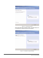
Toolkit Installation . . . . . . . . . . . . . . . . . . . . . . . . . . . . . . . . . . . . . . 11-1
Beltpack Registration . . . . . . . . . . . . . . . . . . . . . . . . . . . . . . . . . . . 11-7
Entering beltpack serial numbers into the basestation . . . . . . . . 11-7
Entering the basestation system ID into the beltpack . . . . . . . . 11-7
Basestation Serial Upgrader . . . . . . . . . . . . . . . . . . . . . . . . . . . . . 11-8
Upgrading the basestation firmware . . . . . . . . . . . . . . . . . . . . . . 11-8
Beltpack Serial Upgrader . . . . . . . . . . . . . . . . . . . . . . . . . . . . . . . 11-11
Installing the Beltpack Upgader. . . . . . . . . . . . . . . . . . . . . . . . . 11-11
Running the Beltpack Upgrader . . . . . . . . . . . . . . . . . . . . . . . . 11-13
Basestation Programming Serial Cable Pinout . . . . . . . . . . . . . . 11-14
Beltpack Programming Serial Cable Pinout . . . . . . . . . . . . . . . . . 11-14
viii
Clear-Com Communication Systems
CellCom V2.0 Instruction Manual
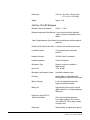
SPECIFICATIONS . . . . . . . . . . . . . . . . . . . . . . . . . 12-1
Notice about Specifications . . . . . . . . . . . . . . . . . . . . . . . . . . . . . 12-4
GLOSSARY . . . . . . . . . . . . . . . . . . . . . . . . . . . . . . 13-1
APPENDIX A: DECT CARRIER FREQUENCY CHART
A-1
LIMITED WARRANTY . . . . . . . . . . . . . . . . . . . . . . . W-I
APPENDIX B: PROGRAMMING MENUS . . . . . . . . B-1
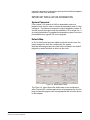
TECHNICAL SUPPORT & REPAIR POLICY. . . . . W-3
TECHNICAL SUPPORT POLICY . . . . . . . . . . . . . . . . . . . . . . . . . . W-3
RETURN MATERIAL AUTHORIZATION POLICY . . . . . . . . . . . . . W-4
REPAIR POLICY . . . . . . . . . . . . . . . . . . . . . . . . . . . . . . . . . . . . . . W-6
Clear-Com Communication Systems
CellCom V2.0 Instruction Manual
ix
x
Clear-Com Communication Systems
CellCom V2.0 Instruction Manual
FIGURES
Figure 1-1 A CellCom Antenna, Beltpack, and Basestation ............ 1-1
Figure 1-2 A CellCom Digital Wireless Communication System ..... 1-3
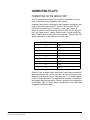
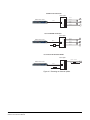
Figure 1-3 Configurations for a Studio and Large-Scale Broadcast Facility.................................................................................................. 1-4
Figure 1-4 Default Map Loaded ....................................................... 1-5
Figure 1-5 Beltpack Configuration with the Default Map ................. 1-6
Figure 2-1 Connect the CellCom Basestation to the Wired Devices 2-2
Figure 2-2 Clear the Basestation’s Memory and Enable the Party Line
2-3
Figure 2-3 Overview of Beltpack Operation..................................... 2-4
Figure 3-1 CellCom Basestation Front Panel .................................. 3-2
Figure 4-1 CellCom Basestation Back Panel................................... 4-1
Figure 4-2 VOX Gating Level on Party Line Connection ................. 4-8
Figure 4-3 VOX Gate Setting Examples .......................................... 4-9
Figure 4-4 Wireless Party Line Audio Flow.................................... 4-10
Figure 4-5 Front View of RJ-45 Connector .................................... 4-11
Figure 4-6 IFB Audio Path ............................................................. 4-15
Figure 4-7 Powering an Antenna Splitter....................................... 4-21
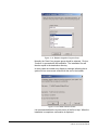
Figure 5-1 Initial Password Request Display ................................... 5-3
Figure 5-2 System Password Menu................................................. 5-3
Figure 5-3 System Password Entry ................................................. 5-3
Figure 5-4 From the MAIN menu, select BELTPACKS ................... 5-4
Figure 5-5 Available Beltpacks Menu .............................................. 5-4
Figure 5-6 First Beltpack Programming Options Menu.................... 5-4
Figure 5-7 Second Beltpack Programming Menu............................ 5-5
Figure 5-8 Editing a Beltpack’s Label .............................................. 5-5
Figure 5-9 Select “Ports” from the Main Menu................................. 5-6
Figure 5-10 First Available Ports Menu ........................................... 5-6
Figure 5-11 Second Available Ports Menu ...................................... 5-6
Figure 5-12 Port Programming Options Menu................................. 5-6
Figure 5-13 Editing a Port’s Label ................................................... 5-7
Figure 5-14 Standard Group Labels ................................................ 5-8
Figure 5-15 Wireless Party Line Group Labels................................ 5-8
Figure 5-16 Select Label from the Menu ......................................... 5-8
Figure 5-17 Group Name Edit Menu................................................ 5-8
Figure 5-18 Group Programming Options Menu ........................... 5-10
Figure 5-19 Adding Members to a Group ...................................... 5-10
Figure 5-20 First Beltpack Menu.................................................... 5-11
Figure 5-21 Second Beltpack Menu .............................................. 5-11
Figure 5-22 Assign communication routes (“labels”) to a beltpack key .
5-12
Figure 5-23 Beltpack Display....................................................... 5-12
Figure 5-24 Select the source/destination to assign to that beltpack key
5-13
Figure 5-25 Key Type Menu .......................................................... 5-13
Figure 5-26 Beltpack Levels Menu ................................................ 5-14
Clear-Com Communication Systems
CellCom V2.0 Instruction Manual
i
Figure 5-27 Beltpack Input Level Setup......................................... 5-14
Figure 5-28 Beltpack Output Level Setup...................................... 5-14
Figure 5-29 Beltpack Latching Menu ............................................. 5-15
Figure 5-30 Beltpack Group Editing Menu..................................... 5-15
Figure 5-31 Beltpack Groups Selected.......................................... 5-15
Figure 5-32 Labels Selected on the Beltpack Menu ...................... 5-16
Figure 5-33 Beltpack Label Editing Menu...................................... 5-16
Figure 5-34 Beltpack Registration Menu ....................................... 5-17
Figure 5-35 Available Audio Ports Menu ....................................... 5-17
Figure 5-36 Selected Port Menu for Level Setting......................... 5-18
Figure 5-37 Port Levels Menu ....................................................... 5-18
Figure 5-38 Port Input Level Setup................................................ 5-18
Figure 5-39 Port Output Level Setup ............................................. 5-18
Figure 5-40 Available Audio Ports Menu ....................................... 5-19
Figure 5-41 Selected Port Menu for Calls...................................... 5-19
Figure 5-42 Port Call Menu............................................................ 5-19
Figure 5-43 Port Destination Select Menu..................................... 5-20
Figure 5-44 Available Audio Ports Menu ....................................... 5-20
Figure 5-45 Selected Port Menu for Calls...................................... 5-20
Figure 5-46 Port Call Menu............................................................ 5-20
Figure 5-47 Port Destination Select Menu..................................... 5-21
Figure 5-48 First Party Line Connection Type Menu ..................... 5-22
Figure 5-49 Second Party Line Connection Type Menu................ 5-22
Figure 5-50 Party Line Noisegate Menu ........................................ 5-23
Figure 5-51 Party Line Noisegate Options Menu........................... 5-23
Figure 5-52 Party Line Noisegate Trigger Level ............................ 5-23
Figure 5-53 VOX Delay Setup ....................................................... 5-23
Figure 5-54 Level Editing Menu for Party Line .............................. 5-24
Figure 5-55 Party Line Input Level................................................. 5-24
Figure 5-56 Party Line Output Level.............................................. 5-24
Figure 5-57 Party Line LoNULL Level ........................................... 5-25
Figure 5-58 Party Line HiNULL Level ............................................ 5-25
Figure 5-59 System Menu 1 .......................................................... 5-26
Figure 5-60 System Menu 2 .......................................................... 5-26
Figure 5-61 System Menu 3 .......................................................... 5-26
Figure 5-62 System Info Menu ...................................................... 5-27
Figure 5-63 Restore Defaults Menu............................................... 5-27
Figure 5-64 ANTENNAS menu...................................................... 5-27
Figure 5-65 IP Address Menu........................................................ 5-28
Figure 5-66 Lock Enable Menu...................................................... 5-29
Figure 5-67 Remote MIC Kill Menu .............................................. 5-29
Figure 5-68 Battery Level Menu ................................................... 5-30
Figure 6-1 Overview of Beltpack Functions ..................................... 6-1
Figure 6-2 View of Top of Beltpack.................................................. 6-2
Figure 6-3 View of Front of Beltpack ............................................... 6-4
Figure 6-4 View of Back of Beltpack................................................ 6-5
Figure 6-5 View of Bottom of Beltpack ............................................ 6-6
Figure 6-6 Battery Discharge Characteristics .................................. 6-8
Figure 6-7 How the beltpack displays its six communication routes......
6-10
ii
Clear-Com Communication Systems
CellCom V2.0 Instruction Manual
Figure 7-1 Connection Information Display ................................... 7-12
Figure 8-1 CellCom Transceiver/Antenna ....................................... 8-1
Figure 8-2 CellCom Transceiver/Antenna Bottom/Control Panel .... 8-2
Figure 8-3 CellCom Splitter Front Connector Panel ........................ 8-6
Figure 8-4 CellCom Splitter Rear Connector Panel......................... 8-7
Figure 9-1 A Beltpack’s Site Survey Screen.................................... 9-4
Figure 9-2 Mapping overlapping coverage zones............................ 9-5
Figure 9-3 ANTENNAS menu.......................................................... 9-6
Figure 10-1 Configuration Editor Initial Screen.............................. 10-1
Figure 10-2 Map Select Screen ..................................................... 10-2
Figure 10-3 Configuration Editor Serial Timeout ........................... 10-3
Figure 10-4 Configuration Setup.................................................... 10-3
Figure 10-5 Map Upload Progress................................................. 10-4
Figure 10-6 Configuration Editor Ethernet Timeout ....................... 10-4
Figure 10-7 Configuration Setup.................................................... 10-5
Figure 10-8 Beltpacks Tab............................................................. 10-7
Figure 10-9 Beltpack List ............................................................... 10-7
Figure 10-10 Beltpack Label.......................................................... 10-8
Figure 10-11 Registering a Beltpack ............................................. 10-8
Figure 10-12 Beltpack Serial Number............................................ 10-9
Figure 10-13 Beltpack Overview.................................................... 10-9
Figure 10-14 Beltpack Defaults Setup ......................................... 10-10
Figure 10-15 Beltpack Page Number .......................................... 10-13
Figure 10-16 Beltpack Key Assignments..................................... 10-14
Figure 10-17 Input and Output Levels ......................................... 10-17
Figure 10-18 Ports Tab................................................................ 10-17
Figure 10-19 Party Line Port Type Menu..................................... 10-18
Figure 10-20 Cross Point List for Port ......................................... 10-19
Figure 10-21 Party Line Crosspoint Type .................................... 10-19
Figure 10-22 Groups Tab ............................................................ 10-20
Figure 10-23 Group Overview Display......................................... 10-21
Figure 10-24 Antennas Tab ......................................................... 10-21
Figure 10-25 Antenna Cable Length Setup ................................. 10-22
Figure 10-26 IFB Configuration Tab ............................................ 10-22
Figure 10-27 IFB Selection List ................................................... 10-23
Figure 10-28 Dim Level List......................................................... 10-23
Figure 10-29 System Tab ............................................................ 10-24
Figure 10-30 Password Entry ...................................................... 10-24
Figure 10-31 Password Entered .................................................. 10-25
Figure 10-32 Country Setup ........................................................ 10-25
Figure 11-1 Previous Version Uninstall ......................................... 11-2
Figure 11-2 Toolkit Install Startup.................................................. 11-3
Figure 11-3 Toolkit Installer Names............................................... 11-3
Figure 11-4 Toolkit Installation Path .............................................. 11-4
Figure 11-5 Toolkit Start Menu Setup............................................ 11-5
Figure 11-6 Toolkit Install Confirm................................................. 11-6
Figure 11-7 Installation Completion Display .................................. 11-6
Figure 11-8 Upgrading Basestation Firmware ............................... 11-8
Figure 11-9 Select Firmware File................................................... 11-9
Figure 11-10 Firmware Download ................................................. 11-9
Clear-Com Communication Systems
CellCom V2.0 Instruction Manual
iii
Figure 11-11 Download Timeout ................................................. 11-10
Figure 11-12 Beltpack Upgrader Installation Start....................... 11-11
Figure 11-13 Set Installation Directory ........................................ 11-11
Figure 11-14 Beltpack Upgrader Program Group........................ 11-12
Figure 11-15 Installer Version Conflict......................................... 11-12
Figure 11-16 Installation Completed............................................ 11-13
Figure 11-17 Beltpack Upgrader Startup ..................................... 11-13
Figure 11-18 Beltpack Upgrade Progress ................................... 11-13
Figure B-1 Basestation Programming Menus.................................. B-1
iv
Clear-Com Communication Systems
CellCom V2.0 Instruction Manual
TABLES
Table 4-1 Party Line Pinout ............................................................. 4-4
Table 4-2 CellCom Basestation 4-Wire Pinout .............................. 4-12
Table 4-3 Pinouts for Connecting to Other Digital Matrix Intercom Systems ............................................................................................... 4-13
Table 4-4 IFB Key Configurations.................................................. 4-15
Table 4-5 Pin Assignments for Stage Announce Connector ......... 4-16
Table 4-6 Pinout for Cable to Upgrade Basestation Firmware ...... 4-17
Table 4-7 Pinout for Cable to Upgrade Beltpack Firmware ........... 4-18
Table 7-1 Connection Information ................................................. 7-13
Table 9-1 How antennas are numbered .......................................... 9-6
Table 11-1 Null-Modem Cable Pinout.......................................... 11-14
Table 11-2 Beltpack Programming Serial Cable Pinout .............. 11-14
Table A-1 DECT Carrier Frequency Chart....................................... A-1
Clear-Com Communication Systems
CellCom V2.0 Instruction Manual
i
ii
Clear-Com Communication Systems
CellCom V2.0 Instruction Manual
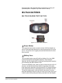
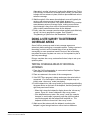
IMPORTANT SAFETY
INSTRUCTIONS
Please read and follow these instructions before operating a CellCom wireless
communication system. Keep these instructions for future reference.
(1) WARNING: To reduce the risk of fire or electric shock, do not
expose this apparatus to rain or moisture.
(2) Do not use the apparatus near water.
Please read and follow these
instructions before operating
a CellCom wireless
communication system.
(3) Clean only with a dry cloth.
(4) Do not block any ventilation openings. Install in accordance
with the manufacturer’s instructions. Install the CellCom wireless
communication system according to the directions in the
Installation Chapter of this manual.
(5) Do not install near any heat sources such as radiators, heat
registers, stoves, or other apparatus (including amplifiers) that
produce heat. Do not place naked flame sources such as candles
on or near the matrix.
(6) Do not defeat the safety purpose of the polarized plug or
grounding-type plug. A polarized plug has two blades with one
wider than the other. A grounding-type plug has two blades and a
third grounding prong. The wide blade or the third prong are
provided for your safety. If the provided plug does not fit into your
outlet, consult an electrician for replacement of the obsolete
outlet.
(7) Protect power leads from being walked on or pinched
particularly at plugs, at convenience receptacles, and at the point
where they exit from the apparatus.
Note: A “convenience receptacle” is an extra AC power outlet
located on the back of a piece of equipment, intended to allow
you to power other equipment.
(8) Only use attachments/accessories specified by the
manufacturer.
(9) Use only with the cart, stand, tripod, bracket, or table specified
by the manufacturer, or sold with the apparatus. When a cart is
used, use caution when moving the cart/apparatus combination
to avoid injury from tip-over.
(10) Unplug the apparatus during lightning storms or when
unused for long periods of time.
(11) Refer all servicing to qualified service personnel. Servicing is
required when the apparatus has been damaged in any way, such
Clear-Com Communication Systems
CellCom V2.0 Instruction Manual
i
as a power-supply cord or plug is damaged, liquid has been
spilled or objects have fallen into the apparatus, the apparatus
has been exposed to rain or moisture, does not operate normally,
or has been dropped.
(12) The CellCom wireless communication system contains a
non-user serviceable battery.
CAUTION: Danger of explosion if battery is incorrectly replaced.
Replace only with the same or equivalent type.
Lithium batteries can overheat or explode if they are shorted.
When you handle the CPU card or a loose battery, DO NOT touch
any external electrical conductors to the battery’s terminals or to
the circuits that the terminals are connected to.
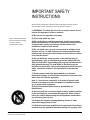
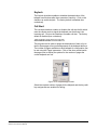
Please familiarize yourself with the safety symbols in Figure 1.
When you see these symbols on a CellCom wireless
communication system, they warn you of the potential danger of
electric shock if the system is used improperly. They also refer
you to important operating and maintenance instructions in the
manual.
CAUTION
RISK OF ELECTRIC SHOCK
DO NOT OPEN
This symbol alerts you to the presence of uninsulated dangerous
voltage within the product’s enclosure that might be of sufficient
magnitude to constitute a risk of electric shock. Do not open
the product’s case.
This symbol informs you that important operating and maintenance instructions are included in the literature accompanying
this product.
Safety Symbols
EMC AND SAFETY
The CellCom wireless communication system meets all relevant
CE, FCC, UL, and CSA specifications set out below:
EN55103-1 Electromagnetic compatibility. Product family
standard for audio, video, audio-visual, and entertainment
lighting control apparatus for professional use. Part 1:
Emissions.
ii
Clear-Com Communication Systems
CellCom V2.0 Instruction Manual
EN55103-2 Electromagnetic compatibility. Product family
standard for audio, video, audio-visual, and entertainment
lighting control apparatus for professional use. Part 2: Immunity.
UL 60065-7, CAN/CSA-C22.2 No.60065-3, IEC 60065-7 Safety
requirements.
And thereby compliance with the requirement of Electromagnetic
Compatibility Directive 2004/108/EC and Low Voltage Directive
2006/95/EC
This device complies with Part 15 of the FCC Rules. Operation is
subject to the following two conditions: (1) this device may not
cause harmful interference, and (2) this device must accept any
interference received, including interference that may cause
undesired operation.
Clear-Com Communication Systems
CellCom V2.0 Instruction Manual
iii
iv
Clear-Com Communication Systems
CellCom V2.0 Instruction Manual
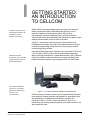
1
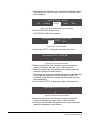
A CellCom system consists
of three basic elements: the
basestation, wireless
beltpack, and antenna.
GETTING STARTED:
AN INTRODUCTION
TO CELLCOM
With a CellCom wireless beltpack users can roam freely around a
studio or production facility while talking and listening to all, or
selected, members of the production team. With up to six
communication routes, the beltpack gives users the flexibility to
communicate quickly and seamlessly with individuals or groups, and to
change communication routes as often as needed.
CellCom™ is the North American name for the award-winning
FreeSpeak® technology, the world’s first wireless system to include
local route programming, crosspoint level control, groups, and full
non-blocking mixing facilities.
With the basic three
elements the user can design
a digital wireless system for
specific requirements.
The CellCom basestation
functions as a full-duplex
digital matrix switcher and
router for voice
communications.
Clear-Com Communication Systems
CellCom V2.0 Instruction Manual
In the United States the system operates in the unlicensed 1.92 GHz to
1.93 GHz band. With its unique and innovative digital technology,
which continually searches for unused radio frequency (RF) channels,
CellCom avoids the noise and interference issues associated with
traditional wireless systems using congested UHF and VHF bands.
Figure 1-1: A CellCom Antenna, Beltpack, and Basestation
CellCom allows a wireless system to be set up specifically tailored to
local needs by locating antennas and beltpacks in areas where they
are needed most. And because the beltpacks operate in the
unlicensed 1.92 to 1.93 GHz frequency spectrum, there is no
interference with existing wireless systems, even those located in the
same production area.
1-1
CellCom may be used stand-alone or connected with party-line and/or
digital matrix intercom systems. The basestation holds connections for
several wired interfaces, including party lines, 4-wire sources, a
program audio source, and a stage announce output device. When
wired to the basestation, these devices communicate seamlessly with
the wireless beltpacks. Party-line beltpacks and 4-wire matrix stations
and panels can key directly to wireless beltpack by name.
Each antenna can support
communications with up to
five wireless beltpacks
operating within its coverage
zone.
CELLCOM FEATURES
Features of CellCom include:
• Basestation in one rack unit (1 RU).
• Up to twenty wireless beltpacks.
• Point-to-point and small group wireless communications.
• Up to six communication routes per beltpack.
• Party-line beltpacks, 4-wire devices, program audio source, and
stage announce output seamlessly included in communication
system.
• IFB functionality with up to five IFB audio sources configurable on the
basestation.
• Up to five standard groups configurable on the basestation.
• Up to five wireless party line groups configurable on the basestation.
• Up to ten remote transceiver/antennas create custom coverage
zones.
• Transceiver/antennas can be located up to 1,000 meters (3,200 feet)
using 24 AWG cable or up to 500 meters (1,600feet) using 26
AWG cable over CAT-5 cable from the basestation avoiding
expensive RF cable.
Note: It is recommended that shielded CAT-5 cable is used for all
CellCom installations.
• Five-character labels for each beltpack and wired connection.
• Communication groups can be created, customized, and assigned to
beltpack keys.
• License-free operation in the 1.9 GHz band—above television and
other wireless communications.
• Frequency-hopping DECT technology automatically finds clear
spectrum.
• Base functions like a digital matrix; each beltpack has a “virtual port”
timeslot.
• Secure system—beltpacks are registered to a particular base and
can frequency hop.
1-2
Clear-Com Communication Systems
CellCom V2.0 Instruction Manual
.
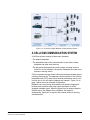
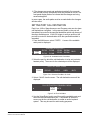
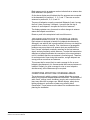
Figure 1-2: A CellCom Digital Wireless Communication System
A CELLCOM COMMUNICATION SYSTEM
A CellCom system consists of three basic elements:
• The wireless beltpacks.
• The basestation that routes communication to and from wireless
beltpacks and other audio devices.
• The transceiver/antennas that provide custom coverage zones in
which four to five beltpacks can operate. Beltpacks can roam freely
between coverage zones.
CellCom operates using a cellular network of antennas located around
a working environment. The antennas connect directly to the CellCom
basestation with CAT-5 cable. Each antenna provides an area or “cell”
in which four to five full-duplex beltpacks can operate. Figure 1-2 on
page 3 above shows an example configuration.
Beltpacks can roam among and between cells without dropping off
because each antenna continually signals a beltpack as to the
strongest available signal. When the signal from an antenna starts to
diminish due to the distance from a beltpack, the beltpack
automatically “hands off” its signal to the nearest antenna, ensuring
smooth transfer.
Clear-Com Communication Systems
CellCom V2.0 Instruction Manual
1-3
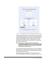
Figure 1-3: Configurations for a Studio and Large-Scale Broadcast Facility
Using an antenna splitter allows up to five antennas to be connected to
one base-station antenna port. A single CellCom basestation supports
up to twenty beltpacks and up to ten antennas, giving a great deal of
flexibility in placing beltpacks where they are needed most, and for
providing wireless reliability. Figure 1-3 illustrates how a CellCom
system can be set up to operate in a single studio or in a large-scale
permanent broadcast facility.
Note: Each antenna is designed to handle five beltpacks
simultaneously in good conditions. However, if interference
or propagation problems occur in an area, to ensure proper
operation and reliability, it may be more practical to install
four beltpacks for each antenna.
For zones which are likely to need coverage for five or more beltpacks
simultaneously it is recommended that a second antenna is installed.
Similarly, for good coverage for nine or more beltpacks simultaneously,
a third antenna may be required.
Note for North American customers: The limited bandwidth of
1.92–1.93 GHz allows one RF cell to accommodate a maximum of five
1-4
Clear-Com Communication Systems
CellCom V2.0 Instruction Manual
transceiver antennas. A basestation can therefore furnish two separate
cells with a total of ten antennas.
IMPORTANT INSTALLATION INFORMATION
System Password
From release V2.0 onwards a CellCom basestation requires a
password to be input in order to activate the basestation when it is first
configured. The password requires the unique basestation system ID
and will normally be supplied with the installation CD for a new unit. If
an existing basestation is upgraded the basestation system ID must be
provided before an upgrade CD can be supplied.
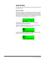
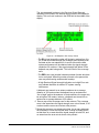
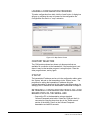
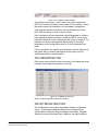
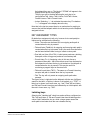
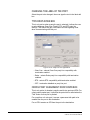
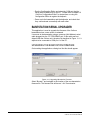
Default Map
In V2.0 a default map has been added to help the first time user; the
map is designed to work like a simple party-line system.
Note that the analogue party-line ports are not included in the default
map as they would introduce an echo into the audio.
Figure 1-4: Default Map Loaded
The Figure 1-4 above shows the default map on the configuration
editor; the two WPL (wireless party-lines) are programmed on the first
page and the other page are left un-programmed and will not be shown
on the beltpack.
Clear-Com Communication Systems
CellCom V2.0 Instruction Manual
1-5
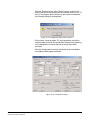
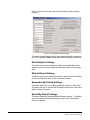
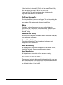
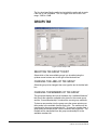
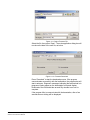
Figure 1-5: Beltpack Configuration with the Default Map
Figure 1-5 shows how each beltpack key will be configured by the
default map.
1-6
Clear-Com Communication Systems
CellCom V2.0 Instruction Manual
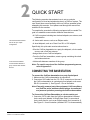
2
QUICK START
The following exercise demonstrates how to set up a simple
configuration of wired and wireless devices in a CellCom system. The
user should have some familiarity with how CellCom operates before
attempting this exercise. If not please read through the manual first,
and then do the exercise.
To complete the exercise the following equipment will be needed.The
goal is to establish communication between these devices:
• A CellCom system including two wireless beltpacks, an antenna, and
a basestation.
This exercise demonstrates
how to set up a simple
configuration.
• A 4-wire audio source, such as an Eclipse matrix.
• A wired beltpack, such as a Clear-Com 501 or 601 beltpack.
Specifically, this quick-start exercise shows how to:
• Wire the CellCom basestation to a party-line beltpack, a 4-wire audio
source, and a CellCom antenna.
• Assign labels to two CellCom beltpacks.
• From the CellCom basestation, create a group containing the wired
and wireless devices.
In this exercise establish
communication between a
group of wired and wireless
devices.
• Initiate calls between members of the group.
Note: For a quick overview of the CellCom programming menus,
refer to Appendix 2.
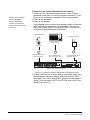
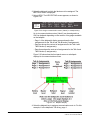
CONNECTING THE BASESTATION
To connect the CellCom basestation to a party-line beltpack
1. Make sure the CellCom basestation is powered off.
2. Connect an XLR cable from the “PL CH-A” connector on the rear of
the CellCom basestation to a wired party-line beltpack, such as an
RS-601 (connection 1). See Figure 2-1 for an illustration.
Note: Externally powered party-line equipment, CellCom splitters,
and CellCom active antennas should always be connected
and powered up before powering the CellCom basestation.
To Connect the CellCom Basestation to a 4-wire matrix port
1. Connect a CAT-5 cable from the CellCom basestation’s leftmost
4-wire audio port (labeled “4-Wire/Eclipse Ports”) to an external
4-wire audio source, such as an Eclipse matrix port (connection 2).
See Figure 2-1 for an illustration (shielded CAT-5 is recommended).
Clear-Com Communication Systems
CellCom V2.0 Instruction Manual
2-1
To Connect to the CellCom Basestation to an Antenna
Always power up external
party-line equipment,
CellCom splitters, and
CellCom active antennas
before powering the CellCom
basestation.
1. Connect a CAT-5 cable from transceiver port 1 on the CellCom
basestation’s rear panel to a CellCom antenna (connection 3). See
Figure 2-1 for an illustration (shielded CAT-5 is recommended).
2. Power up the basestation.
3. Power up the beltpacks.
If the beltpacks do not connect to the basestation within 30 seconds,
check that they are registered to the basestation. If they are not,
refer to the chapter “CellCom Configuration Editor” for instructions
on registering the beltpacks to the basestation.
Party-Line Beltpack
CellCom Antenna
Eclipse Matrix
Channel A
1
2
3
Connect XLR cable to
party-line beltpack
Connect CAT-5 cable
to 4-wire audio source
Connect CAT-5 cable to
CellCom antenna
POWER
PL CH-A
PL CH-B
PRGM IN
SA OUT
4-WIRE / ECLIPSE PORTS
SA RLY
1
2
3
4
BASE
LOOP
LAN
TRANSCEIVER
PC PROGRAM
1
2
90-260V, 50/60Hz
80 Watts
CellCom Base Station Rear Panel
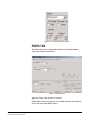
Figure 2-1: Connect the CellCom Basestation to the Wired Devices
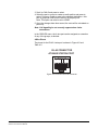
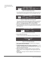
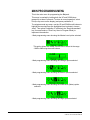
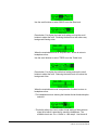
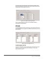
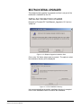
4. To get the CellCom into a “clean” state for the example below, from
the basestation’s front-panel display, scroll to and select PORTS,
then 4WIR1, then CALLS, then NONE. (NONE is the last element in
the list.) Then also select PORTS, then PLCHA, then CALLS, then
NONE (See Figure 2-2).
2-2
Clear-Com Communication Systems
CellCom V2.0 Instruction Manual
Figure 2-2: Clear the Basestation’s Memory and Enable the Party Line
5. Enable the party line by pressing the CH A enable button on the
basestation’s front panel until the CH A enable light illuminates (see
Figure 2-2). Auto-nulling should be performed after the party line
circuit is connected. Pressing and holding the enable button for
eight seconds activates the auto-nulling.
Note: Be aware that a loud tone is generated in the party-line
beltpack’s headset during auto-nulling. This tone enables
the basestation to perform auto-nulling of the party line.
Clear-Com Communication Systems
CellCom V2.0 Instruction Manual
2-3
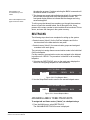
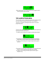
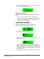
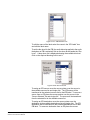
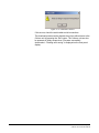
OVERVIEW OF BELTPACK OPERATION
Figure 2-3: Overview of Beltpack Operation
ASSIGNING LABELS TO THE CELLCOM
BELTPACKS
To assign a name (“label”) to CellCom beltpack #1
1. From the basestation’s front-panel display, use the setup/enter knob
to select BELTPACKS, then BPK01, and then LABEL.
Rotate the setup/enter knob until the desired item is highlighted.
Press the knob in to select the item.
2. Rotate the setup/enter knob again to select the alphanumeric
character to be edited, then push the setup/enter knob in to select
2-4
Clear-Com Communication Systems
CellCom V2.0 Instruction Manual
the character. Rotate the knob to select the character to replace it
with. Press the knob in to select the new character.
3. When selecting characters for the beltpack’s item label is complete
press the setup/enter knob again to save.
4. To exit the menu, select and then deselect (by pressing the knob
again) the fifth character in the menu.
5. The changes are saved and applied automatically five seconds after
the last time the setup/enter knob is pressed or turned. The
front-panel display flashes to indicate that the changes are being
saved and applied.
6. Repeat this entire process for the second wireless beltpack, BPK02.
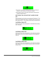
CREATING A GROUP
To create a group
1. From the basestation’s front panel, use the setup/enter knob to
scroll to and select GROUPS, then GP#01, then MEMBERS.
If entries in the MEMBERS menu are already in the group these
menu entries are outlined. An outline around a menu entry means
that it is a member of the group. When an item is selected an outline
appears around it. When the item is selected again, the outline
disappears.
2. Select the following members of the group: 4WIR1, PLCHA, BPK01,
BPK02, so that only these entries are outlined.
3. To exit the Group Members menu, scroll to and select BACK from
the basestation’s front-panel menu.
4. The changes are saved and applied automatically five seconds after
the last time the setup/enter knob was pressed or turned. The
front-panel display flashes to indicate that the changes are being
saved and applied.
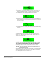
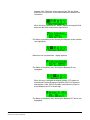
ASSIGNING THE GROUP LABEL TO
CELLCOM BELTPACK KEYS
The next step is to assign the group label created in the previous step,
GP#01, to the first key of each of the CellCom wireless beltpacks.
To assign the group label to the first key of CellCom beltpack #1
1. From the basestation’s front-panel menu select BELTPACKS, then
BPK01, then KEYS. A list will be displayed showing how the 3
pages of 2 keys are currently assigned on beltpack #1.
2. Select “Pg1-1” to edit the first key of the first page. A list of
destinations will be displayed this key can be assigned to. Rotate
the setup/enter knob clockwise until “GP#01” is highlighted, then
press the knob to select it. The basestation’s display should display
the key options.
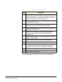
• TLK - talk key
Clear-Com Communication Systems
CellCom V2.0 Instruction Manual
2-5
• LIS - listen key
• T+L - talk and listen key
• DTL - dual talk and listen key
• FL - forced listen key
• TFL - talk and forced listen key
3. Select DTL using the setup/enter knob and press the knob to select
it.
4. Select BACK, then BACK again to return to the list of beltpacks.
5. The changes are saved and applied automatically five seconds after
the last time the setup/enter knob was pressed or turned. The
front-panel display flashes to indicate that the changes are being
saved and applied.
6. Repeat the procedure for beltpack #2.
CALLING THE GROUP FROM THE BELTPACKS
To call the group from beltpack #1
1. If beltpack #1 is not set to page #1 (indicated by the numbers in the
center of the display), use the beltpack’s left and right scroll buttons
to move to page 1.
The label under the left-hand rotary controller should now read
GRP01.
2. If the key is programmed to DTL on the basestation press the rotary
controller briefly to latch the listen path to “on” or press and hold the
rotary controller to talk.
• The red talk light and green listen light next to the rotary controller
should light.
• If the path is latched to Listen pressing and releasing the rotary
controller will delete the path and the red and green lights will
extinguish.
• If the rotary controller is being held to create a talk path releasing it
will delete the path. The red and green lights will be extinguished
when the talk path is deleted.
• Examine the wired beltpack attached to party-line channel A.
It should be possible to hear audio from beltpack #1 in the wired
beltpack’s headset. If the microphone of the wired beltpack is
opened the wireless beltpack should also be able to hear the
audio.
• The 4-wire device should have 2-way audio. The wireless
beltpack should be able to hear audio from the 4-wire device, and
the 4-wire device should be able to hear audio from the wireless
beltpack.
2-6
Clear-Com Communication Systems
CellCom V2.0 Instruction Manual
• Examine wireless beltpack #2. If it is on page #1, the green
(listen) light should be flashing and it should be possible to hear
audio from beltpack #1. At this point, beltpack #1 won’t be able to
hear audio from beltpack #2.
3. Press the leftmost rotary knob on beltpack #2, which is next to the
flashing green light.
All stations are able to hear beltpack #2 as well as beltpack #1. In
other words, all stations can hear each other.
4. Press the leftmost rotary controllers on beltpacks #1 and #2 briefly
to unlatch them. This deactivates all talk and listen paths.
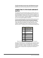
CALLING THE GROUP FROM THE 4-WIRE
AUDIO DEVICE
1. From the basestation’s front-panel menu, select PORTS, then
4WIR1, then CALLS, then GP#01.
The changes are saved and applied automatically five seconds after
the last time the setup/enter knob is pressed or turned. The
front-panel display flashes to indicate that the changes are being
saved and applied.
• All stations should now be able to hear the audio coming in from
the 4-wire device.
• On the two wireless beltpacks, the green (listen) lights should be
flashing, indicating an incoming call to group #1 from a member of
group #1.
2. Note that if the basestation is power cycled off and on again, the talk
paths from the 4-wire device are automatically re-established to the
wired beltpack and to the two wireless beltpacks.
3. It is possible to remove the talk paths from the 4-wire device to the
wired beltpack and to the two wireless beltpacks by selecting
PORTS, then 4WIR1, then CALLS, then NONE, from the
basestation’s front-panel menu.
4. Note that if the calling 4-wire port is included in the group that is
being called from the 4-wire device the 4-wire audio will not be
looped back to itself.
CALLING THE GROUP FROM THE WIRED
PARTY-LINE BELTPACK
1. From the basestation’s front-panel menu, select PORTS, then
PLCHA, then CALLS, then GP#01.
The changes are saved and applied automatically five seconds after
the last time the setup/enter knob is pressed or turned. The
front-panel display flashes to indicate that the changes are being
saved and applied.
2. After a few seconds talk from the wired beltpack’s microphone.
Clear-Com Communication Systems
CellCom V2.0 Instruction Manual
2-7
• Audio from the wired beltpack should be audible on the two
wireless beltpacks, and on the 4-wire audio device.
On the wireless beltpacks. the green (listen) light should be
flashing, indicating an incoming call to group #1 from a member of
group #1.
• Audio from the 4-wire audio device will be audible from the wired
beltpack’s headset.
3. If the basestation is powered down and then up again, the talk paths
from the wired beltpack (on party-line channel A) are re-established
to the 4-wire device and to the two wireless beltpacks.
4. It is possible to remove the talk paths from the wired beltpack’s party
line to the other devices by selecting PORTS, then PLCHA, then
CALLS, then NONE. This may also be done by disabling the party
line from the front panel of the CellCom basestation by using the CH
A and CH B enable buttons provided that the party line is powered
from the basestation as this will remove the power rather than the
audio. It will not remove the talk paths if the party line is externally
powered.
CREATING A WIRELESS PARTY LINE
To create a wireless party line
1. From the basestation’s front panel, use the setup/enter knob to
scroll to and select GROUPS, then WP#01, then MEMBERS.
If entries in the MEMBERS menu are already in the wireless party
line these menu entries are outlined. An outline around a menu
entry means that it is a member of the wireless party line. When an
item is selected an outline appears around it. When the item is
selected again, the outline disappears.
2. Select the following members of the wireless partry line: 4WIR1,
PLCHA, BPK01, BPK02, so that only these entries are outlined.
3. To exit the Wireless Party Line Members menu, scroll to and select
BACK from the basestation’s front-panel menu.
4. The changes are saved and applied automatically five seconds after
the last time the setup/enter knob was pressed or turned. The
front-panel display flashes to indicate that the changes are being
saved and applied.
ASSIGNING THE WIRELESS PARTY LINE
LABEL TO CELLCOM BELTPACK KEYS
The next step is to assign the wireless party line label created in the
previous step, WP#01, to the first key of each of the CellCom wireless
beltpacks.
To assign the wireless party line label to the first key of CellCom
beltpack #1
2-8
Clear-Com Communication Systems
CellCom V2.0 Instruction Manual
1. From the basestation’s front-panel menu select BELTPACKS, then
BPK01, then KEYS. A list will be displayed showing how the 3
pages of 2 keys are currently assigned on beltpack #1.
2. Select “Pg1-1” to edit the first key of the first page. A list of
destinations will be displayed this key can be assigned to. Rotate
the setup/enter knob clockwise until “WP#01” is highlighted, then
press the knob to select it. The basestation’s display should display
the key options.
• TLK - talk key
• LIS - listen key
• T+L - talk and listen key
• DTL - dual talk and listen key
• FL - forced listen key
• TFL - talk and forced listen key
3. Select DTL using the setup/enter knob and press the knob to select
it.
4. Select BACK, then BACK again to return to the list of beltpacks.
5. The changes are saved and applied automatically five seconds after
the last time the setup/enter knob was pressed or turned. The
front-panel display flashes to indicate that the changes are being
saved and applied.
6. Repeat the procedure for beltpack #2.
CALLING THE WIRELESS PARTY LINE
FROM THE BELTPACKS
To call the wireless party line from beltpack #1
1. If beltpack #1 is not set to page #1 (indicated by the numbers in the
center of the display), use the beltpack’s left and right scroll buttons
to move to page 1.
The label under the left-hand rotary controller should now read
WPL01.
2. If the key is programmed to DTL on the basestation press the rotary
controller briefly to latch the listen path to “on” or press and hold the
rotary controller to talk.
• The red talk light and green listen light next to the rotary controller
should light.
• If the path is latched to Listen pressing and releasing the rotary
controller will delete the path and the red and green lights will
extinguish.
• If the rotary controller is being held to create a talk path releasing it
will delete the path. The red and green lights will be extinguished
when the talk path is deleted.
Clear-Com Communication Systems
CellCom V2.0 Instruction Manual
2-9
• Examine the wired beltpack attached to party-line channel A.
It should be possible to hear audio from beltpack #1 in the wired
beltpack’s headset. If the microphone of the wired beltpack is
opened the wireless beltpack should also be able to hear the
audio.
• The 4-wire device should have 2-way audio. The wireless
beltpack should be able to hear audio from the 4-wire device, and
the 4-wire device should be able to hear audio from the wireless
beltpack.
• Examine wireless beltpack #2. If it is on page #1, the green
(listen) light should be flashing and it should be possible to hear
audio from beltpack #1. At this point, beltpack #1 won’t be able to
hear audio from beltpack #2.
3. Press the leftmost rotary knob on beltpack #2, which is next to the
flashing green light.
All stations are able to hear beltpack #2 as well as beltpack #1. In
other words, all stations can hear each other.
4. Press the leftmost rotary controllers on beltpacks #1 and #2 briefly
to unlatch them. This deactivates all talk and listen paths.
CALLING THE WIRELESS PARTY LINE
FROM THE 4-WIRE AUDIO DEVICE
1. From the basestation’s front-panel menu, select PORTS, then
4WIR1, then CALLS, then WP#01.
The changes are saved and applied automatically five seconds after
the last time the setup/enter knob is pressed or turned. The
front-panel display flashes to indicate that the changes are being
saved and applied.
• All stations should now be able to hear the audio coming in from
the 4-wire device.
• On the two wireless beltpacks, the green (listen) lights should be
flashing, indicating an incoming call to wireless party line #1 from
a member of wireless party line #1.
2. Note that if the basestation is power cycled off and on again, the talk
paths from the 4-wire device are automatically re-established to the
wired beltpack and to the two wireless beltpacks.
3. It is possible to remove the talk paths from the 4-wire device to the
wired beltpack and to the two wireless beltpacks by selecting
PORTS, then 4WIR1, then CALLS, then NONE, from the
basestation’s front-panel menu.
4. Note that if the calling 4-wire port is included in the wireless party
line that is being called from the 4-wire device the 4-wire audio will
not be looped back to itself.
2-10
Clear-Com Communication Systems
CellCom V2.0 Instruction Manual
CALLING THE WIRELESS PARTY LINE
FROM THE WIRED PARTY-LINE BELTPACK
1. From the basestation’s front-panel menu, select PORTS, then
PLCHA, then CALLS, then WP#01.
The changes are saved and applied automatically five seconds after
the last time the setup/enter knob is pressed or turned. The
front-panel display flashes to indicate that the changes are being
saved and applied.
2. After a few seconds talk from the wired beltpack’s microphone.
• Audio from the wired beltpack should be audible on the two
wireless beltpacks, and on the 4-wire audio device.
On the wireless beltpacks. the green (listen) light should be
flashing, indicating an incoming call to wireless party line #1 from
a member of wireless party line #1.
• Audio from the 4-wire audio device will be audible from the wired
beltpack’s headset.
3. If the basestation is powered down and then up again, the talk paths
from the wired beltpack (on party-line channel A) are re-established
to the 4-wire device and to the two wireless beltpacks.
4. It is possible to remove the talk paths from the wired beltpack’s party
line to the other devices by selecting PORTS, then PLCHA, then
CALLS, then NONE. This may also be done by disabling the party
line from the front panel of the CellCom basestation by using the CH
A and CH B enable buttons provided that the party line is powered
from the basestation as this will remove the power rather than the
audio. It will not remove the talk paths if the party line is externally
powered.
Clear-Com Communication Systems
CellCom V2.0 Instruction Manual
2-11
2-12
Clear-Com Communication Systems
CellCom V2.0 Instruction Manual
3
OPERATING THE
CELLCOM
BASESTATION
INTRODUCTION
The CellCom basestation provides all of the intelligence and signal
routing for the CellCom digital wireless intercom system. The
basestation is effectively a full-duplex digital matrix communications
system, with virtual “ports” for the wireless beltpacks rather than
physical ports.
In its memory, the basestation contains all of the labels and
communications paths assigned to each CEL-BP beltpack, and this
information is sent to the beltpacks via the CEL-TA
transceiver/antennas as soon as they are switched on and recognized
by the base.
The basestation also functions as the interface between wired and
wireless communication devices. The two party-line intercom
connectors, four 4-Wire connectors, and program
input/stage-announce output each have their own full-duplex time slot.
They can be labeled, added to communication groups, and assigned to
beltpacks as desired. Additionally the program input or one of the four
4-Wire connections can be assigned as IFB sources on the
basestation.
Clear-Com Communication Systems
CellCom V2.0 Instruction Manual
3-1
UNDERSTANDING FRONT-PANEL OPERATION
Figure 3-1: CellCom Basestation Front Panel
Pressing the Headset Channel A Talk and A/B Reply buttons (2 & 4)
together will send a call signal to headset channel A. Pressing the A/B
Reply and Headset Channel B Talk buttons (4 & 5) together will send a
call signal to headset channel B.
1 Headset Connector
The 4-pin male XLR-type headset socket connects to Clear-Com
headsets and other headsets with 4-pin female connectors. This
headset connector is for the onboard two-channel intercom, with
controls just to the right of the connector.
2 &
3 Channel A Talk Switch and Light/Listen
Level Knob
The channel A talk switch and associated light, and listen level knob,
allow full-duplex conversations with any CellCom wireless beltpacks or
other communications systems wired to the rear of the basestation to
which the onboard Channel A has been assigned. Assignments are
done via the front-panel programming.
The talk switch is momentary/latching, such that pressing it and
holding down will create a talk path that ends when the user releases
the switch, while quickly tapping it will latch the talk, and a second tap
will release it. The LED lights red when a talk is active.
Turning the listen level knob clockwise will allow the user to hear the
other party’s voice, increasing the level to maximum when fully
clockwise.
The audio level is shown on the beltpack screen next to the battery
display.
3-2
Clear-Com Communication Systems
CellCom V2.0 Instruction Manual
4 A/B Reply Button
Pressing this button will reply to the last caller to call A or B.
5 &
6 Channel B Talk Switch and Light/Listen
Level Knob
The channel B talk switch and associated light, and listen level knob,
function the same as the controls for Channel A.
7 Party Line Channels A and B Enable Switches
The channel A and channel B enable switches and associated lights
activates the power only on the rear-panel to party-line intercom
channels A and B. Activating one or both of these switches enables
the power to that party line but does not affect the audio to the party
line which is always connected. These switches may be “locked” via
the front-panel SYSTEM programming menu so that they may not be
disengaged accidentally.
If the button is held in for more than 8 seconds autonulling mode will be
enabled for the current party line and the following message will be
displayed:
“Release button to begin autonulling”
When the button is release the basestation will perform an autonulling
on the current party line. On completion the following message will be
displayed:
“Party line A Autonulling complete”
for party line A.
8 Program Audio Enable Switch and Light
This latching switch makes any program audio signal that enters via
the rear-panel line-level 3-pin XLR connector available to be assigned
to wireless beltpacks, either separately or mixed with communications
groups. This switch may be “locked” via the front-panel SYSTEM
programming menu so that it may not be disengaged accidentally.
9 Antenna Light Display
These green LEDs, one for each of the ten antennas that the
basestation will support, light when an antenna is connected and
ready.
Clear-Com Communication Systems
CellCom V2.0 Instruction Manual
3-3
10 Display Screen
The display screen shows all of the menus and programming options
that are available within the CellCom system. The user can select a
particular beltpack and view all of its current talk/listen assignments, or
see all of the current members of a particular group. Via the screen
and rotary encoder, labels (5-character user names) can be created
and/or changed, new members assigned to groups, input and output
levels adjusted, and so on.
11 Setup/Enter Knob
The setup/enter knob is used to scroll through the various menu
options within the CellCom basestation, in order to discover specific
information regarding users or to program communications routes and
groups. Turning the knob clockwise scrolls display items toward the
right, and turning the knob counterclockwise scrolls display items
toward the left.
When a desired menu item is highlighted, pushing the setup/enter
knob inward will select that item. The lists of available beltpacks and
groups typically span two or more screens, so when the highlight is at
the leftmost or rightmost part of the screen and the user continues to
turn the rotary encoder in that direction, the display will jump to the
next screen selections (Example: in the beltpack sections, the first
screen shows beltpacks 1 through 5, and the second shows 6 through
10.)
Pressing and holding the Setup/Enter knob for more than three
seconds will return the display to the battery monitor.
12 Power Switch
The power switch will turn the CellCom basestation on and off.
3-4
Clear-Com Communication Systems
CellCom V2.0 Instruction Manual
4
CONNECTING THE
CELLCOM
BASESTATION
The CellCom basestation connects to the following wired interfaces
through its rear-panel connectors:
The CellCom basestation
connects to several wired
interfaces that can
communicate with the
wireless beltpacks.
• Basestation to AC power
• Basestation to party-line channels A and B
• Basestation to program audio source
• Basestation to stage announce output
• Basestation to stage announce relay
• Basestation to 4-wire matrix ports
• Basestation to a second basestation (not used)
• Basestation to a PC
• Basestation to transceiver antennas
UNDERSTANDING THE BACK-PANEL
CONNECTORS
POWER
PL CH-A
PL CH-B
PRGM IN
SA OUT
4-WIRE / ECLIPSE PORTS
SA RLY
1
2
3
4
BASE
LOOP
LAN
8
9
TRANSCEIVER
PC PROGRAM
1
2
90-260V, 50/60Hz
80 Watts
1
2
3
4
5
6
1 - Power Connector
2 - Party Line Channel A Connectors
3 - Party Line Channel B Connectors
4 - Program Input
5 - Stage Announce Output
6 - Stage Announce Relay
7
10
11
7 - 4-Wire Matrix Ports
8 - Base Loop Connector (not used)
9 - LAN Connector
10 - PC Connector
11 - Transceiver Connectors
Figure 4-1: CellCom Basestation Back Panel
Clear-Com Communication Systems
CellCom V2.0 Instruction Manual
4-1
1 IEC Power Connector
The 3-conductor AC power connector and universal power supply
accepts voltages from 90 to 250 volts, at 50/60 Hz. Power
consumption is 80 watts.
2 Party Line Channel A Connectors
The CellCom basestation provides two pairs of party-line connectors,
labeled “Channel A” and “Channel B.” Each pair of female and male
3-pin XLR connectors joins a channel of party-line intercom to the
CellCom, allowing communication between the wired party-line
equipment and CellCom wireless beltpacks. Input and Output level
control is set via the front-panel display programming.
The second connector of each pair is a loop-through, so that the user
can continue the connection to another CellCom basestation or to
another party-line beltpack or station. This connector auto-detects a
connection with a powered party-line channel (30-VDC on Pin 2), and
the basestations’s internal 200-ohm party-line termination and DC
voltage to power PL beltpacks is not activated.
Alternatively, when a wired, unpowered party-line beltpack (up to four)
is connected to PL CH-A with standard two-conductor shielded
microphone cable, the basestation engages the 200-ohm termination
and supplies 24-VDC to the beltpack(s) – allowing them to operate and
communicate with the wireless beltpacks in the system.
3 Party Line Channel B Connectors
These connectors are the same as those for PL CH-A.
4 Program Input Connector
This female 3-pin XLR connector accepts a line-level audio signal from
an outside source such as a mixing console or audio player. It is
transformer-isolated. Level adjustment is done via the front-panel
display programming. The program input can be assigned as an IFB
source from the front panel.
5 Stage Announce Output Connector
This male 3-pin XLR connector allows a line-level audio signal,
typically from wireless beltpacks or 4-Wire sources, to be sent to a
paging system or other audio system. It is transformer-isolated. Level
adjustment is done via the front-panel display programming. More
than one audio source at a time can be routed to the Stage Announce,
with the audio being combined to give a single audio output.
4-2
Clear-Com Communication Systems
CellCom V2.0 Instruction Manual
6 Stage Announce Relay
This DB-9 male connector provides a relay closure that is triggered
simultaneously with the SA Output. The relay may be used to open an
audio pathway for the signal from the SA Output, or could also be used
to activate a light or lock or some other device. The relay may be wired
for normally closed or normally open operation, and the signal appears
on pins 1 & 6 or 2 & 6. It is rated to a maximum of 30-VDC at 1 amp.
7 4-Wire Matrix Ports
These four RJ-45 connectors can connect four full-duplex (input pair
and output pair) audio connections from a 4-wire communications
device, digital matrix intercom, or similar – making them available to
the wireless beltpacks. Any of the 4-wire ports or the program input
can be assigned as IFB sources from the front panel.
Each of these connectors has its own time slot, and can be addressed
separately from a beltpack, or combined with other beltpacks and
rear-panel connectors in a group. Level adjustment is done via the
front-panel display programming.
8 Base Loop Connector (not used)
The connector has no function in Cellcom V2.0.
9 LAN Connector
This RJ-45 connector allows the basestation to be connected to a LAN
for system software upgrades and configuration downloads from the
Configuration Editor. It is a 10BaseT Ethernet port.
10 PC Connector
This female DB-9 connects to a PC computer for firmware updates and
monitoring of the system configuration. It functions as a serial port.
11 Transceiver Connectors
These two RJ-45 connectors connect the basestation to two remote
CEL-TA transceiver/antennas or antenna splitters.
Each wired transceiver/antenna communicates with five wireless
beltpacks. Each antenna splitter provides connection for five
transceiver antennas. providing communication with up to a maximum
of 10 beltpacks depending upon available bandwidth.
Note: To meet FCC emissions requirements a ferrite must be
fitted on any CAT-5 cable plugged into either of the two
ports labeled “transceivers.” The ferrite should be fitted at
Clear-Com Communication Systems
CellCom V2.0 Instruction Manual
4-3
the basestation end of the CAT-5 cable. Position the ferrite
as close to the basestation as possible. A suitable ferrite is
available from Wurth Elektronix. The part number is 742 711
32.
Note: It is recommended that shielded CAT-5 cable is used for
CellCom systems.
CONNECTING TO PARTY-LINE INTERCOM
SYSTEMS
Up to two channels of party-line intercom can be connected to the
CellCom basestation. The descriptions below will discuss connections
with Clear-Com and compatible party-line, RTS party-line, the ability of
CellCom to power up to four Clear-Com party line beltpacks by itself,
and the front-panel settings associated with these party-line
connections.
Using the front-panel display and rotary encoder, the user may go into
the PORTS menu, select the desired party-line channel, and create a
five-character alphanumeric label for it. This is the label that would
then appear on any CellCom wireless beltpacks to which that party-line
connection was assigned for communications. In the GROUPS menu,
the party-line connection can be assigned as a member of any of the
groups, as desired.
CLEAR-COM AND COMPATIBLE PARTY-LINE
Clear-Com and Clear-Com-compatible wired party-line intercoms
connect to the PL CH-A and PL CH-B connectors in a similar manner
to connecting beltpacks or remote stations to the intercom line.
Typically that wired intercom connection would have a 30-VDC current
on Pin 2, coming from a main station or an intercom power supply. The
second connector in the pair may be used as a loop-through to go to
other wired party-line stations or beltpacks, or to a second CellCom
basestation. The pinout for party line connector is shown in table
Table 4-1.
PIN
DESCRIPTION
1
Ground (shield)
2
Power
3
Audio
Table 4-1: Party Line Pinout
To connect party-line equipment to the basestation
1. Check that the party-line LED on the front-panel is out, which
indicates that the party-line connection is disabled from the
basestation.
4-4
Clear-Com Communication Systems
CellCom V2.0 Instruction Manual
2. Connect, and if appropriate, power up, the external party-line
equipment.
3. Enable the party line by pressing the “enable” button on the
basestation’s front panel.
The basestation detects power and termination settings when the party
line is enabled by pressing the “enable” button on the basestation’s
front panel, or when the basestation is powered up after having
enabled the party line. The basestation remembers that the party line
is enabled when it powers up.
When the CellCom basestation detects a wired party line being
connected with 30 VDC on Pin 2, it does not enable the 24-VDC power
supply that the CellCom basestation supplies to the connector to
support a handful of locally connected wired party-line beltpacks. The
basestation then appears to the wired party-line system as a remote
station.
The first call to a Party Line channel A or B results in the call alert and
subsequent ones do not give any further alerting unless the Party Line
channel buttons on the basestation are toggled. This prevents all calls
giving alerts when this is not necessary.
CONNECTING DIRECTLY TO CLEAR-COM
PARTY-LINE BELTPACKS
PL CH-A and PL CH-B have the ability to directly support up to four
Clear-Com RS-501 or RS-601 party-line beltpacks each, without any
other connection to a wired party-line system. This feature gives the
convenience of being able to add a few wired beltpacks when needed
to a CellCom installation.
Connect a standard two-conductor shielded microphone cable to the
PL CH-A connector, and then connect it to a Clear-Com single-channel
party-line beltpack. Enable the party line and the basestation will
enable the required 200-ohm termination, and will supply 24-VDC to
Pin 2 to power the beltpack(s).
It is possible to daisy-chain up to four beltpacks, or use an intercom
XLR splitter at the basestation to feed mic cables connected to the
individual beltpacks. Because it is a 24-volt rather than a 30-volt
current, the maximum length of cable that can be connected (the sum
of all of the runs) will be shorter than what is expected with the
standard party-line voltage. Do the same with PL CH-B to support an
additional four beltpacks.
To connect to the party line
1. From the main menu, scroll to PORTS and select by pressing the
setup/enter knob in.
2. Scroll to PLCHA or PLCHB and press to select.
The SELECTED PORT screen appears.
3. Scroll to and select CALLS.
Clear-Com Communication Systems
CellCom V2.0 Instruction Manual
4-5
The CALL DESTINATION screen appears.
4. Select the port or group to be connected to the party line by scrolling
to it and pressing the rotary encoder. Doing so creates a route to the
selected destination—this port or group can now hear the activity on
the party line. (Note: this option can also be set to NONE.)
5. Select TYPE from the menu.
6. Select either Clear-Com, Drake, or RTS.
The basestation automatically sets the termination, audio levels,
and call signaling options for the selected party-line system.
Note that the Basestation does not detect the RTS call signal.
7. If the changes are saved the route will be reinstated on power up.
Note: Suggested settings for a party line connection are that the
VOX should be set to -26dB, the gain output to -6dB and the
input to 0dB.
CONNECTING TO AN RTS™ WIRED BELTPACK
CellCom can only transmit and receive audio from channel 2 of an
RTS wired beltpack. Connect using a standard XLR cable. Ensure that
the party-line type is set to “RTS” using the menu on the basestation
before enabling the party line. See the chapter “Programming a
System from the Basestation” for more information.
Warning: Previous versions of this manual described a cable
which would allow access to channel 1 of a dual channel
RTS beltpack. DO NOT attempt to use a cable like this as
it could result in damage to the CellCom basestation.
FRONT-PANEL ADJUSTMENTS FOR PARTY-LINE
CONNECTIONS
To connect the party-line channels to CellCom and make the
communication available to the rest of the system, press the CH-A
and/or CH-B enable switches. The LED will light, and the connection is
made. To disconnect the party-line connections, press these switches
again. The switch may be “locked” in the SYSTEM menu so that the
party lines may not be disconnected.
Because party-line intercom does not have global level control on a
channel, input and output level controls are provided via the front panel
programming. Scroll to PORTS on the main display screen and press
the rotary encoder to select. Scroll to PLCHA or PLCHB and press to
select. Select LEVELS, then select the input or output level. (This
notation is relative to the basestation–input level refers to the level at
which everyone else hears the party line, and output level refers to the
level at which the users on the party line channel hear everyone else.)
Use the rotary encoder to adjust the numerical level—clockwise to
increase the level and counter-clockwise to decrease the level.
4-6
Clear-Com Communication Systems
CellCom V2.0 Instruction Manual
Make the estimated changes in level and press the rotary encoder to
save the changes. Test the levels between the party line and CellCom
beltpack, and make additional changes as needed. When the levels
are set as desired, press to select and the display will go to the
previous INPUT/OUTPUT screen. When both are adjusted select
BACK on each screen until the main screen is displayed.
Users connected to the basestation can be forced to listen to the
activity on the party line by initiating a “call.”
For more information on programming the basestation, see the chapter
“Programming a System from the Basestation”.
Clear-Com Communication Systems
CellCom V2.0 Instruction Manual
4-7
TROUBLESHOOTING PARTY-LINE CONNECTIONS
Reducing CellCom Beltpack echo when talking to a
analogue party-line
If the basestation and beltpack are not set up correctly the CellCom
user will experience an echo when talking to a party-line (either directly
or via a group or a wireless party-line). The echo is caused by either
local audio coupling in the headset due to the microphone gain being
set too high or audio reflections from the party-line that can minimized
by setting a VOX gate on the party-line and the party-line being auto
nulled.
How to set the microphone gain in the beltpack
When using a CC-260 or CC-95 the microphone gain should be set at
55dB (55dB is the default setting).
Note: If the microphone gain is set higher than 55dB this can
introduce audio coupling between the ear phone and the
microphone.
Include the Party-Line channel inside a Wireless Party-Line
group
It is recommended that when connecting to an analogue party-line
system that the user includes the wireless party-lines (WPL). The
WPLs reduce the variation in audio levels heard when talking to
analogue party-lines. The WPLs are created in the configuration editor
in a similar way to a user creating a group.
How to set the VOX gating level on the Party-Line connected
to the Basestation
Figure 4-2: VOX Gating Level on Party Line Connection
4-8
Clear-Com Communication Systems
CellCom V2.0 Instruction Manual
The VOX gate allows the user to set limits to the audio that will be
passed from the party-line to the basestation mixer; by setting the VOX
level at the correct level the user can cut the audio reflections (which
cause the echo) from the party-line when a wireless beltpack user
speaks. This is achieved when the VOX level is set above the audio
level of the reflections, thus allowing a party-line user’s voice to pass
through the VOX gate in the basestation mixer but the VOX gate will
reject the audio reflections.
Note: If both the party-line user and the CellCom user speak at the
same time, the CellCom user may hear the echo as the
audio reflections piggy back the party-line audio.
Figure 4-3: VOX Gate Setting Examples
Note: If the CellCom beltpack users shouts or increases the
microphone gain into the beltpack the echo might return if
the audio reflects are above the VOX gate level.
Auto null the Party-Line channel at the Basestation
Party-lines connected to the base station can be auto nulled by first
enabling party-line channel by pressing the party-line button on the
front of the basestation.
The auto nulling is then activated by pressing and holding the enable
party-line button; the base station will go then into a auto null routine.
Clear-Com Communication Systems
CellCom V2.0 Instruction Manual
4-9
WIRELESS PARTY-LINE
The CellCom basestation provides five wireless party line groups
which allow up to twenty eight members to be connected together in a
conference call. The beltpack keys assigned to the wireless party line
group are assigned as dual talk and listen and party lines connected to
the group are assigned as talk and listen.
When a beltpack or party line talks to a wireless party line group the
talk signal from the beltpack or party line is subtracted from the listen
signal to remove the sidetone resulting from the users voice being
looped back in the conference audio, leaving only the audio from other
members.
Figure 4-4: Wireless Party Line Audio Flow
This facility allows conferencing over a large area between a mix of
beltpacks, party line stations and Eclipse system panels through a
CellCom basestation.
CONNECTING TO 4-WIRE AND DIGITAL
MATRIX INTERCOM
Up to four channels of 4-wire/digital matrix intercom can be connected
to the CellCom basestation. The descriptions below will discuss
connections with Clear-Com Matrix Plus digital matrix, Clear-Com
Eclipse digital matrix, other brands of digital matrix intercoms, other
4-wire audio devices, and the front-panel settings associated with
these 4-wire connections.
To connect the basestation to a matrix port
1. Scroll to PORTS on the main display screen and press the rotary
encoder to select.
2. Scroll to 4-WIRE and press to select.
4-10
Clear-Com Communication Systems
CellCom V2.0 Instruction Manual
3. Scroll to CALLS and press to select.
4. Select the port or group to create an audio path to and press to
select. Doing so creates a route to the selected destination—this
port or group can now hear the activity on the party line.
Note: This option can also be set to NONE.
5. Once the changes have been saved, the route will be reinstated on
power up.
Note: Call signalling is not currently supported on 4-wire
connections.
In the GROUPS menu, the 4-wire port can be assigned as a member
of any of the groups, as desired.
4-Wire Pinout
The pinout for the RJ-45 4-wire port is shown in Figure 4-5 and
Table 4-2.
RJ-45 CONNECTOR
AT BASE STATION PORT
8 7 65 4 32 1
Figure 4-5: Front View of RJ-45 Connector
Clear-Com Communication Systems
CellCom V2.0 Instruction Manual
4-11
Pin
Description
1
Not used
2
Not used
3
Audio Output +
4
Audio Input +
5
Audio Input -
6
Audio Output -
7
Not used
8
Not used
Table 4-2: CellCom Basestation 4-Wire Pinout
CONNECTING TO CLEAR-COM MATRIX PLUS 3
The connection between a Matrix Plus 3 digital intercom port and a
CellCom 4-wire port is accomplished with a standard 4-pair
straight-through CAT-5 data cable with RJ-45 connectors on both
ends. In the current generation of CellCom, the audio input and audio
output pairs are all that will be used.
In the Matrix Plus 3 PGM-WIN configuration software, set the matrix
port that is connected to the CellCom basestation 4-wire port to
“4-Wire”. If the label of this CellCom 4-wire port is to be put onto more
than one intercom panel within the matrix system, and any and all
people who have activated a talk/listen to that port will be allowed to be
able to hear each other, as well as hearing the person talking to them
from the CellCom wireless beltpack, also check “Party-Line Enable” for
that 4-Wire connection in the configuration software.
Within the CellCom Basestation configuration software, the user can
adjust the input and output level for that port. Alternately, the input and
output levels can be adjusted on the CellCom basestation for the
particular 4-wire port, using the front-panel display. Repeat the
procedure for each CellCom 4-wire port that is connected with the
Matrix Plus system. Note that CellCom does not currently generate a
call signal to the Matrix port.
CONNECTING TO CLEAR-COM ECLIPSE DIGITAL
MATRIX
The procedure to connect between a CellCom 4-wire port and the
Eclipse digital matrix is similar to that of Matrix Plus 3. An identical
connection is made with 4-pair straight-through CAT-5 cable between
an Eclipse port and the CellCom port.
Within the Eclipse Configuration System software (ECS), set the port
to “Direct.” This will allow intercom panels in the Eclipse system to
converse with the CellCom basestation and beltpacks. Because there
4-12
Clear-Com Communication Systems
CellCom V2.0 Instruction Manual
is not a “Party-Line Enable” within Eclipse, if several users of intercom
panels connected with Eclipse need to hear each other as well as the
wireless CellCom beltpack, another procedure will need to be added.
Within the configuration software, the user would create a new
party-line label, with members including the desired intercom panels
and the particular CellCom 4-wire port. That label would then be
assigned to a key on each of the intercom panels, allowing connection
with the CellCom 4-wire port and the other members of the new
party-line.
Within the CellCom Basestation configuration software, the user can
adjust the input and output level for that port. Alternately, the input and
output levels can be adjusted on the CellCom basestation for the
particular 4-wire port, using the front-panel display. Repeat the
procedure for each CellCom 4-wire port that is connected with the
Eclipse system.
CONNECTING WITH OTHER DIGITAL MATRIX INTERCOM SYSTEMS
Because CellCom features standard 4-wire ports, with an input pair
and an output pair, virtually any 4-wire signal can be connected with it.
Make sure to properly match the input and output pairs between the
digital matrix port and the CellCom 4-wire port (see diagram below).
The pinouts for the first two 4-wire ports contain both audio and data
connections, though the data connections are not currently used.
Those pinouts are shown in the following table.
PIN
FUNCTION
1
Data Tx+
2
Data Tx–
3
Audio Out+
4
Audio In+
5
Audio In–
6
Audio Out–
7
Data Rx+
8
Data Rx–
Table 4-3: Pinouts for Connecting to Other Digital Matrix Intercom Systems
The remaining two 4-wire connections are audio only, and the data
connections are unterminated (see Table 4-2).
Within the configuration software of the other digital intercom system,
configure its connected port to 4-wire or similar. Adjust the input and
Clear-Com Communication Systems
CellCom V2.0 Instruction Manual
4-13
output levels either at matrix side or within the CellCom front-panel
display for the particular CellCom 4-wire port.
CONNECTING WITH OTHER 4-WIRE DEVICES
Various other 4-wire audio devices can be connected with CellCom.
The Clear-Com EF-701M 4-wire interface can be used to attach
additional party-line channels to CellCom, converting them from
party-line on the wired side to 4-wire on the CellCom side.
The Clear-Com IF4W4 interface can be used similarly. The audio input
side of the CellCom 4-wire connectors could be used for additional
program or other audio inputs that could then be accessed by CellCom
beltpacks. The audio output side of the CellCom 4-wire connectors
could be used to route a CellCom wireless beltpack user’s voice out of
the system for paging or other reasons, similar to the SA OUT
connector.
When using the CellCom 4-wire ports in this way, make sure that
proper connections are made between CellCom and the other device.
Adjust the input and/or output levels either at the 4-wire device or
within the CellCom front-panel display for that particular 4-wire port.
CONNECTING TO A PROGRAM AUDIO
SOURCE
CellCom can connect with a program audio source, making it
accessible to be assigned by itself to a communication path to one or
more CEL-BP wireless beltpacks, or to be added to a group with other
communications and assigned to beltpacks. Using the two separate
rotary encoder volume controls on the beltpack, the user can monitor
the program on one control while talking and listening on an intercom
channel with the other.
The balanced female 3-pin XLR connector accepts a standard audio
signal from a mixing console or similar, with Pin 1 ground, Pin 2 audio
hot (+), and Pin 3 audio cold (-).This connector is transformer-isolated.
To make the program input signal available to the system, the
front-panel PRGM enable button must be activated/on. The red LED
above it will light, indicating that it is now available. This front-panel
switch may be “locked” to prevent accidental disengagement, using
the front panel display.
Using the front-panel display and rotary encoder, the user may select
PORTS and give the connector a five-character alphanumeric label.
The user may assign that program input by itself to a beltpack using
the BELTPACKS menu, or use the GROUPS menu to assign the
program input to any group or wireless party line. Program input can
be assigned to multiple groups or wireless party lines using the
GROUPS menu.
4-14
Clear-Com Communication Systems
CellCom V2.0 Instruction Manual
IFB CONFIGURATION
One of five CellCom basestation inputs can be defined as a source for
an IFB. These inputs are the Program Input and the four 4-Wire ports.
All the 4-Wire ports, party line channels, beltpacks, wireless party lines
and stage output can be defined as IFB destinations.
Up to ten IFB key configurations can be set up that group together an
IFB source and a number of IFB destinations and set the dimming level
for that IFB key configuration.
IFB Source
IFB Destination
IFB Talks
Program Audio
Four-wire 3
Four-wire 4
All beltpacks
All beltpacks
Four-wire 3
Four-wire 4
All beltpacks
All beltpacks
Four-wire 4
Four-wire 3
All Beltpacks
All beltpacks
Table 4-4: IFB Key Configurations
An IFB talk is a panel or beltpack with a key set up to talk to the IFB
key configuration. Whenever an IFB talk key is pressed the audio from
the IFB source to the IFB destinations configured in the IFB key
configuration is dimmed by the set amount and the audio from the IFB
talk is heard by all the IFB destinations set up in that IFB key
configuration.
Figure 4-6: IFB Audio Path
Clear-Com Communication Systems
CellCom V2.0 Instruction Manual
4-15
The IFB source audio will be dimmed on the IFB destinations for as
long as the IFB talk key is active. When the IFB talk key is released
the IFB source audio to the destinations will return to normal level.
CONNECTING TO THE STAGE ANNOUNCE
OUTPUT
The stage announce feature allows a talker to route their voice to an
external paging system or other audio destination by pressing one of
the rotary encoders to which the SA OUT connector is assigned. The
adjacent SA RELAY is simultaneously triggered. One beltpack user at
a time may use this feature, though the capability may be assigned to
any or all of the wireless beltpacks, as desired.
Connect a microphone cable to the male 3-pin XLR connector on the
rear of the CellCom basestation, and connect the other end to the
external audio system. When the output is activated, the beltpack
user’s voice will be sent at line level to the audio system. The audio
output ceases when the beltpack user stops pressing the rotary
encoder; it is good practice to make sure that any rotary encoder to
which the SA OUT is assigned is set to momentary/non-latching mode.
PIN
FUNCTION
1
Normally Closed
2
Normally Open
3
N/C (no connection)
4
N/C
5
N/C
6
Pole
7
N/C
8
N/C
9
N/C
Table 4-5: Pin Assignments for Stage Announce Connector
The associated SA RELAY can be assigned to open an audio route for
the paging or announcement, or can be assigned to initiate any other
event such as turning on a light or activating a lock. It is rated at a
maximum of 30 VDC at 1 ampere. The relay can be wired to be either
normally open or normally closed, using the pinout information in
Table 4-5.
4-16
Clear-Com Communication Systems
CellCom V2.0 Instruction Manual
CONNECTING TO A PC
CONNECTING VIA THE SERIAL PORT
The PC serial port on the rear of the CellCom basestation is mainly
used for firmware version upgrades of the system.
A specially wired cable is required for these updates, consisting of two
9-pin D-type connectors for the PC and the CellCom ends. On the
CellCom end, a male 9-pin D connector is used, and is wired as
follows in relation to the D connector pins on the PC end. Pin 2 goes to
pin 3, pin 3 goes to pin 2, and pin 5 goes to pin 5; in other words, the
data Tx and Rx lines on pins 2 and 3 are reversed. Those are the only
wiring connections on the CellCom end of the cable.
PC CONNECTION (9-PIN F)
BASESTATION (9-PIN M)
1
N/C
2
3
3
2
4
N/C
5
5
6
N/C
7
N/C
8
N/C
9
N/C
Table 4-6: Pinout for Cable to Upgrade Basestation Firmware
On the PC end, a female 9-pin D connector is used. Make sure that the
data connections of pin 2 to pin 3 and pin 3 to pin 2 are followed, and
that pin 5 goes through to pin 5. Then short pins 1, 4, 6, and 8 together
on the PC end of the cable. The cable will now be ready to use with the
any upgrade files from the factory. Table 4-6 gives the pin configuration
for this cable. Table 4-7 shows the pin configuration for the cable used
to upgrade beltpack firmware.
Clear-Com Communication Systems
CellCom V2.0 Instruction Manual
4-17
PC CONNECTION (9-PIN F)
BELTPACK (3.5 mm jack)
1
N/C
2
tip
3
ring
4
N/C
5
screen
6
N/C
7
N/C
8
N/C
9
N/C
Table 4-7: Pinout for Cable to Upgrade Beltpack Firmware
CONNECTING VIA THE LAN PORT
This connection is used for rapid firmware updates, as well as in the
future for system configuration and intelligent connection with the
Eclipse digital matrix. It is wired as a standard Ethernet connection.
The basestation has a fixed IP address. This can be found by selecting
SYSTEM and then INFO from the front-panel display menu. Refer to
the chapter “CellCom Toolkit” for more information on using the LAN
port to upgrade firmware.
CONNECTING TO
TRANSCEIVER/ANTENNAS (CEL-TA)
CONNECTING ONE TRANSCEIVER/ANTENNA
(CEL-TA) DIRECTLY TO A TRANSCEIVER PORT
A CEL-TA transceiver/antenna connects to the transceiver port on the
CellCom basestation using a standard 4-pair CAT-5 data cable with
RJ-45 connectors. It may be located up to 1,000 meters from the
basestation if 24AWG cable is used or 500 meters if 26AWG cable is
used, creating a coverage area for five CEL-BP wireless beltpacks in
that location. The port is able to provide the required power to the
transceiver/antenna at a distance of up to 300 meters (approximately
900 feet); beyond that distance, the CEL-TA transceiver/antenna must
be locally powered via its in-line external universal power supply.
Note: It is recommended that shielded CAT-5 cable is used.
To know that a CEL-TA transceiver/antenna is active, observe the
green power LED and the yellow signal LED on the face of the unit
where the RJ-45 connector is connected. Both must be lit. Also,
4-18
Clear-Com Communication Systems
CellCom V2.0 Instruction Manual
wireless beltpacks in the vicinity of the active transceiver/antenna will
be connected to the system and their displays will show labels and
other information.
Using both transceiver ports, a basestation may be connected with up
to two transceiver/antennas via a direct connection with the
basestation. For the best, most reliable coverage, it is advisable to use
a minimum of two transceiver/antennas in any installation, positioned
in different locations in the coverage area. When more CEL-TA’s are
required to support a larger coverage area or more wireless beltpacks,
an antenna splitter will need to be introduced between the basestation
and the transceiver/antennas.
Note: In some situations, particularly in outdoor venues,
interference from non-DECT sources can severely reduce
the range of the system. In these cases we recommend a
site survey as described in Chapter 8, “Installing a System”.
CONNECTING TRANSCEIVER/ANTENNAS WITH A
SPLITTER (PD2203)
A splitter (PD2203) will connect up to five transceiver/antennas to one
of the transceiver ports on the CellCom basestation, creating up to five
coverage zones that can be overlapped to make large areas where
CEL-BP wireless beltpacks can have continuous coverage. The use of
the splitter also extends the distance that the CEL-TA transceiver
antennas can be located from the basestation to 2,000 meters (6,400
feet) if 24AWG cable is used or 1,000 meters (3,200 feet) if 26AWG
cable is used (assuming the same cable type is used to connect the
antenna to the splitter and the splitter to the basestation).
Note: It is recommended that shielded CAT-5 cable is used.
For example, a splitter can be used to connect to a CellCom
basestation that is located in a production truck outside an arena or
stadium, with a single CAT-5 cable going to the splitter which is then
located just inside the stadium. From that splitter, up to five CEL-TA
transceiver/antennas are distributed throughout the stadium to create
wide coverage – each with a run of CAT-5 cable back to the splitter. A
similar arrangement may be used in a large theatre or performing arts
facility.
The connection between a transceiver port on the CellCom
basestation and a PD2203 splitter is accomplished with standard
4-pair CAT-5 data cable with RJ-45 connectors. It is connected to the
port labeled MATRIX on the splitter. This cable can be as long as 1,000
meters (3,200 feet) if 24AWG cable is used or 500 meters (1,600 feet)
if 26AWG cable is used. The splitter must be locally powered via its DC
IN connector, using the in-line external universal power supply. The
RJ-45 ports on the splitter labeled “1” through “5” are the connections
to the CEL-TA transceiver/antennas. Transceiver/antennas connected
Clear-Com Communication Systems
CellCom V2.0 Instruction Manual
4-19
to the splitter can be powered at a distance of up to 300 meters (900
feet); beyond that distance they will need to be locally powered.
Note: To use the system with cable lengths over 200m the
software update in release 1.5.6 or better must be installed
on the basestations.
POWERING AN ANTENNA OR ANTENNA SPLITTER
Provision of 24 VDC power to a CellCom antenna is done in one of
three ways:
• Connect the antenna to a 150/UNI-DIN power supply unit through the
4-pin DIN connector at the antenna.
• Connect the antenna to an antenna splitter which is powered by a
power-supply unit.
• Connect the antenna to a CellCom basestation’s “transceiver” RJ-45
connector.
The preferred method is to connect the antenna to a powered antenna
splitter, as illustrated in Figure 4-7. An antenna splitter distributes
power to all antennas connected to it. A single power-supply unit can
power the maximum 10 antennas. However, cable lengths will be
reduced.
4-20
Clear-Com Communication Systems
CellCom V2.0 Instruction Manual
POWERED BY BASE STATION ONLY
Antenna Splitter
1
CellCom Base Station
100 m
2
100 m
3
100 m
4
100 m
5
100 m
100 m
M
PSU AT THE ANTENNA SPLITTER ONLY
Antenna Splitter
CellCom Base Station
500 m
M
PSU
1
300 m
2
300 m
3
300 m
4
300 m
5
300 m
DC
AC
PSU AT THE SPLITTER AND ACTIVE ANTENNA
Antenna Splitter
1
CellCom Base Station
800 m -- 1000 m
PSU
2
AC
500 m
M
DC
3
4
5
PSU
AC
DC
Figure 4-7: Powering an Antenna Splitter
Clear-Com Communication Systems
CellCom V2.0 Instruction Manual
4-21
4-22
Clear-Com Communication Systems
CellCom V2.0 Instruction Manual
5
A system is programmed
using the menus displayed
on the basestation’s front
panel.
Scroll to an item by turning
the setup/enter knob. Select
an item by pressing the knob
in, as if it were a pushbutton.
PROGRAMMING A
SYSTEM FROM THE
BASESTATION
A CellCom system is programmed using the menus displayed on the
basestation’s front panel. Programming the system requires four basic
steps:
1. Create individual names (“labels”) for the wireless beltpacks
and for the wired devices connected to the basestation. Use
individual labels for building “point-to-point” communication paths.
Labels are composed of five alphanumeric characters. Labels can
be created for users’ names (“John” or “Susan”), roles (“AUDIO” or
“DIR”), or for connections (“PL_A” or “PL_B”).
Alternatively a device’s generic name can be used, which never
changes. An example of a generic name is “BPK01” for Beltpack 1.
Generic names are always displayed on the programming menus.
2. Create names (“labels”) for groups. A group label is used when a
CellCom beltpack needs to communicate with all members of a
group simultaneously, as in a party line. Up to ten groups can be
created, with five groups being standard groups and five groups
being wireless party line groups. Up to fifteen members can be
assigned to a standard group and up to twenty eight members can
be assigned to a wireless party line group.
A label can be customized to reflect the group’s function, such as
“STG-A” for communicating with the production staff on Stage A.
Alternatively the generic names assigned for the ten possible
groups can be used. For example, “GP#01” is the generic name for
Group 1.
3. Assign members to the groups created. Group members are
drawn from the wireless beltpacks and from the wired devices
connected to the basestation. A group created from these devices
functions as a party line, in which all members of the group can
communicate simultaneously with all other members of the group.
4. Assign individual and grouped devices to each CellCom
beltpack by using the programming screens on the
basestation’s front panel. Each assignment creates a
communication route from the CellCom beltpack to the selected
device or group. Up to six communication routes can be assigned to
a beltpack.
These steps are discussed in more detail in the following sections.
Clear-Com Communication Systems
CellCom V2.0 Instruction Manual
5-1
“Source” refers to a
device—beltpack, intercom
station, or a variety of other
devices—from which audio is
received.
“Destination” refers to a
device to which audio is sent.
There are two ways to save
changes.
A NOTE ABOUT TERMINOLOGY
In this manual, the term “source” refers to a device—beltpack,
intercom station, or a variety of other devices—that sends audio to a
beltpack. It represents a “listen” path to a station. The term
“destination” refers to a device to which audio is sent. It represents a
“talk” path from a beltpack.
The names of these sources and destinations appear in the display of
a beltpack and are called “labels”. A label is a 5-character
alphanumeric name that identifies a source, destination, or control
function accessed by a beltpack. These “labels” are programmed from
the CellCom basestation.
USING THE BASESTATION’S PROGRAMMING MENUS
A CellCom system is programmed using the programming menus that
appear on the basestation’s front-panel display screen. The user
navigates through the menus to select programming options for the
system.
Rotating the setup/enter knob allows the user to scroll through the
selections on the screen. As the user scrolls through the menu items
are highlighted on the screen. To select an item as a new programming
option, press the setup/enter knob in, as if it were a pushbutton, when
the desired item is highlighted on the screen.
SAVING CHANGES
The changes are saved and applied automatically when changes are
made to the unit’s programming. Five seconds after the last time the
setup/enter knob was turned or pressed, the front-panel display
flashes to indicate that the changes are being saved and applied.
BASESTATION PASSWORD
With the CellCom V2.0 release the basestation requires a password to
be input before it will operate once the firmware is upgraded. The
password requires the basestation system ID which is found in the
system information screen (see “System INFO (“INFO”)” on page 5-27.
The basestation password will normally be supplied with the V2.0 CD
but if it is not available the user should contact Clear-Com for a
password.
After the basestation is upgraded it will display the following message
when the first map is downloaded.
5-2
Clear-Com Communication Systems
CellCom V2.0 Instruction Manual
INVALID PASSWORD - SYSTEM DISABLED - ENTER SYSTEM -> PASSWORD
Figure 5-1: Initial Password Request Display
To enter the password press the Setup/Enter knob to display the main
menu and select ‘SYSTEM’. Scroll through the system menus until the
‘PASSWORD’ menu is displayed.
INFO
SYSTEM MENU
PASSWORD BACK
INVALID PASSWORD - SYSTEM DISABLED - ENTER SYSTEM -> PASSWORD
Figure 5-2: System Password Menu
Scroll to the ‘PASSWORD’ entry and select it. The password entry
screen will be displayed.
Enter SYSTEM ENABLE password. . .
A A D4EAJ0
BACK
Figure 5-3: System Password Entry
The first character is a string of eight characters will be highlighted
ready for the system password to be entered.
1. Scroll to and select the alphanumeric character to be changed. A
box appears around the character.
2. Rotate the setup/enter knob. As the knob is rotated the entire range
of available characters appears, starting with upper-case
characters, proceeding to lower-case characters, then to digits, and
finally to punctuation characters.
3. When the desired new character appears, press the setup/enter
knob to select it. The box disappears, and is replaced by the solid
highlight.
4. Repeat steps 1 through 3 to enter all the characters in the system
password.
5. When editing the label has been completed press the Setup/Enter
knob. The system should display the message “PASSWORD
ACCEPTED - MATRIX RESETTING”.
6. The matrix will reset and begin normal operation. If the password is
incorrectly entered the system will reject it.
Once the system password has been entered the ‘PASSWORD’ entry
will no longer be displayed on the system menu.
Clear-Com Communication Systems
CellCom V2.0 Instruction Manual
5-3
CHANGING BELTPACK LABELS
Use individual labels for
point-to-point communication
routes.
The first step in creating a CellCom system is to create individual
names (“labels”) for the wireless beltpacks and for the wired devices
connected to the basestation. Use individual labels for building
“point-to-point” communication routes.
To change a beltpack label
1. From the MAIN menu on the basestation’s front panel display, scroll
to and select BELTPACKS, as shown in Figure 5-4.
.
MAIN MENU
PORTS
BELTPACKS
GROUPS
SYSTEM
Figure 5-4: From the MAIN menu, select BELTPACKS
The AVAILABLE BELTPACKS menu appears, as shown in Figure
5-5. The first page shows the first five beltpack labels.
BPK01
BPK01
AVAILABLE BELTPACKS
BPK02
BPK03
BPK04
BPK02
BPK03
BPK04
BPK05
BPK05
BACK
Figure 5-5: Available Beltpacks Menu
• The beltpacks’ generic labels BPK01 through BPK05 appear on
the upper row, while the labels given to the beltpacks appear just
under the generic labels. At first both upper and lower labels will
have the same generic designations.
• To get to the second, third and fourth pages, scroll all the way to
the right of the screen, and then continue to scroll. The second,
third and fourth pages will be displayed showing beltpacks 6 - 10,
11 - 15 and 16 - 20 (BPK06 - BPK10, BPK11 - BPK15, BPK16 BPK20).
2. Scroll to and select the desired beltpack label.
The next menu that appears gives the options for programming the
selected beltpack, as shown in Figure 5-6.
SELECTED BPK01 - BPK01
KEYS
LATCH
GROUPS
BACK
Figure 5-6: First Beltpack Programming Options Menu
3. Scroll all the way to the right of the screen and continue to scroll.
The second beltpack programming options menu will be displayed.
5-4
Clear-Com Communication Systems
CellCom V2.0 Instruction Manual
SELECTED BPK01 - BPK01
Port labels identify the
devices wired to the
basestation’s rear panel
ports.
LABELS
LEVELS
REGISTER
BACK
Figure 5-7: Second Beltpack Programming Menu
4. Scroll to and select LABEL from the menu.
A menu to edit the selected beltpack’s label appears, as shown in
Figure 5-8. The current 5-character label appears, just under its
generic name.
Enter name for - BPKO1
Audio ports include headset,
4-wire, party line, stage
announce, and program
source labels.
A U D I
O BACK
Figure 5-8: Editing a Beltpack’s Label
5. Scroll to and select the alphanumeric character to be changed. A
box appears around the character.
6. Rotate the setup/enter knob. As the knob is rotated the entire range
of available characters appears, starting with upper-case
characters, proceeding to lower-case characters, then to digits, and
finally to punctuation characters.
7. When the desired new character appears, press the setup/enter
knob to select it. The box disappears, and is replaced by the solid
highlight.
8. Repeat steps 4 through 6 for all the characters in the label that are
to be changed.
9. When editing the label has been completed, select and then
de-select the fifth character to return to the PROGRAMMING
OPTIONS menu.
Note: The user must select the fifth character, even if it is blank,
as in a label with less than five characters.
10. The changes are saved and applied automatically five seconds
after the last time the setup/enter knob was pressed or turned. The
front-panel display flashes to indicate that the changes are being
saved and applied.
11. The beltpack that has had a new label assigned to it should be
power cycled to ensure it is updated with the new label.
To edit another beltpack label, scroll clockwise to the BACK command
and select it. The AVAILABLE BELTPACKS screen appears. Select a
new beltpack label to edit, and repeat steps 2 through 9.
Clear-Com Communication Systems
CellCom V2.0 Instruction Manual
5-5
SETTING AND CHANGING PORT LABELS
Port labels are created to identify the audio devices wired to the
basestation’s rear panel ports, such as party-line beltpacks, 4-wire
devices, program sources, and stage-announce outputs and relays.
To create a port label
1. From the basestation’s MAIN menu, scroll to and select PORTS
(see Figure 5-9).
MAIN MENU
BELTPACKS
The upper label retains the
same generic label, while
the lower label can be edited
to the user requirements.
PORTS
GROUPS
SYSTEM
Figure 5-9: Select “Ports” from the Main Menu
The first AVAILABLE AUDIO PORTS menu is displayed, as shown in
Figure 5-10.
HDSTA
HDSTA
AVAILABLE AUDIO PORTS
4WIR2 4WIR3
HDSTB 4WIR1
4WIR2 4WIR3
HDSTB 4WIR1
BACK
Figure 5-10: First Available Ports Menu
The first page of the menu shows the first 5 ports, starting with
HDSTA (front-panel headset A) and continuing through 4WIR3 (the
third 4-wire connector on the rear panel), as shown in Figure 5-10.
By scrolling all the way to the right, and then continuing to scroll,
4WIR4 through PRGRM (program) will be displayed (Figure 5-11).
4WIR4
4WIR4
AVAILABLE AUDIO PORTS
STGAN PRGRM
PLCHA PLCHB
STGAN PRGRM
PLCHA PLCHB
BACK
Figure 5-11: Second Available Ports Menu
Note: The upper character of the pair is a generic label, while the
lower character is editable.
2. Select an audio port from the menu. A screen appears that gives the
options for programming the selected port, as shown in Figure 5-12.
SELECTED HDSTA - HDSTA
KEY
GROUPS
LEVELS
LABEL
BACK
Figure 5-12: Port Programming Options Menu
5-6
Clear-Com Communication Systems
CellCom V2.0 Instruction Manual
3. Select LABEL from the menu.
A menu to edit that port’s label appears as shown in Figure 5-13.
Enter name for - HDSTA
V I D E O BACK
Figure 5-13: Editing a Port’s Label
4. Scroll to and select the alphanumeric character to be changed. A
box appears around the character.
5. Rotate the setup/enter knob. As the knob is rotated the entire range
of available characters appears, starting with upper-case
characters, proceeding to lower-case characters, then to digits, and
finally to punctuation characters.
6. When the desired new character appears, press the setup/enter
knob to select it. The box disappears, and is replaced by the solid
highlight.
7. Repeat steps 4 through 6 for all the characters in the label that are
to be changed.
8. Select ‘BACK’ to save the label. The front-panel display flashes to
indicate that the changes are being saved and applied.
In order to edit another port label, scroll clockwise to the BACK
command and select it. The AVAILABLE AUDIO PORTS menu
appears. Select a new audio port to edit, and repeat steps 2 through 9.
SETTING AND CHANGING GROUP LABELS
A group label is used when a CellCom beltpack needs to communicate
with all members of a group simultaneously, as in a party line. The user
can create up to ten groups. Five of these can be standard groups
with up to fifteen members per group and five can be wireless party
line groups with up to twenty eight members per group.
Group members can be individual beltpacks or wired devices
connected to the basestation. To form a group, the user must first
create a name or “label” for the group, and then assign members to the
group.
To create a group label
1. From the main menu, select GROUPS. The first page of the
AVAILABLE GROUPS menu appears, as shown in Figure 5-14.
The 5 standard group labels appear on the first page of the menu.
The generic labels GP#01 through GP#05 appear on the top row,
and their editable versions appear on the lower row. The default
values are GRP01 through GRP05.
Clear-Com Communication Systems
CellCom V2.0 Instruction Manual
5-7
First create a group label,
and then add members to the
group.
AVAILABLE GROUPS
GP#01 GP#02 GP#03 GP#04 GP#05 BACK
GRP02 GRP01 GRP02 GRP03 GRP04
Figure 5-14: Standard Group Labels
By scrolling all the way to the right, and then continuing to scroll, the
wireless party line groups appear on the second page of the menu.
WP#01
WPL01
AVAILABLE GROUPS
WP#02 WP#03 WP#04 WP#05 BACK
WPL02 WPL03 WPL04 WPL05
Figure 5-15: Wireless Party Line Group Labels
The generic wireless party line group labels WP#01 through WP#05
appear on the top row, and their editable versions appear on the
lower row. The default values are WPL01 through WPL05.
2. From the AVAILABLE GROUPS menu, select a group label. A menu
appears that gives the options for programming the selected group,
as in Figure 5-16.
SELECTED GP#01 - GRP01
LABEL
BACK
MEMBERS
Figure 5-16: Select Label from the Menu
3. Select LABEL from the menu.
A menu to edit that group label appears, as shown in Figure 5-17.
Enter name for - GP#01
S T G - A BACK
Figure 5-17: Group Name Edit Menu
4. Scroll to and select the alphanumeric character to be changed. A
box appears around the character.
5. Rotate the setup/enter knob. As the knob is rotated the entire range
of available characters appears, starting with upper-case
characters, proceeding to lower-case characters, then to digits, and
finally to punctuation characters.
6. When the desired new character appears, press the setup/enter
knob to select it. The box disappears, and is replaced by the solid
highlight.
7. Repeat steps 4 through 6 for all the characters in the label that are
to be changed.
5-8
Clear-Com Communication Systems
CellCom V2.0 Instruction Manual
8. Select ‘BACK’ to save the label. The front-panel display flashes to
indicate that the changes are being saved and applied.
In order to edit another group label scroll clockwise to the BACK
command and select it. The AVAILABLE GROUPS menu appears.
Select a new group label to edit, and repeat steps 2 through 9.
Clear-Com Communication Systems
CellCom V2.0 Instruction Manual
5-9
ADDING GROUP MEMBERS
When a group name or “label” has been chosen the user may then
“populate” that group. Group members are drawn from the individual
wireless beltpacks and individual wired devices connected to the
CellCom basestation. A group created from these devices functions as
a party line, in which all members of the group can communicate
simultaneously with all other members of the group. A standard party
line group may contain up to fifteen members and a wireless party line
group may contain up to twenty eight members.
To assign members to a group
1. From the MAIN menu, select GROUPS. The AVAILABLE GROUPS
menu appears.
2. Select a group’s label to which members are to be added. The
PROGRAMMING OPTIONS menu appears, as shown in Figure
5-18.
SELECTED GP#01 - STG-A
LABEL
MEMBERS
BACK
Figure 5-18: Group Programming Options Menu
3. Select MEMBERS from the menu.
The MEMBERS menu appears, as shown in Figure 5-19. On this set
of pages, all of the base-station wired ports appear (HDSTA through
PRGRM, “headset A” through “program”), followed by the labels for
all twenty CellCom beltpacks. The menu header displays the
number of members currently in the group out of a possible
maximum of twelve members e.g. 4/12 for four members.
EDITING MEMBERS OF GRP01 - AUDIO (4/12)
HDSTA HDSTB 4WIR1 4WIR2 4WIR3 BACK
HDSTA HDSTB 4WIR1 4WIR2 4WIR3
Figure 5-19: Adding Members to a Group
4. Scroll through the pages of this list to find the desired members for
the group. When a desired member is highlighted, press the
setup/enter knob to select that member. A box appears around it.
5. To de-select a member that has already been selected, highlight that
member and press the setup/enter knob. Pressing the setup/enter
knob effectively works as a toggle switch, first selecting the item by
putting a box around it, and then de-selecting it and removing the
box.
6. When all of the desired beltpack labels and base-station port labels
have been selected, scroll clockwise to BACK and select it to exit
5-10
Clear-Com Communication Systems
CellCom V2.0 Instruction Manual
Each beltpack can
accommodate up to six
labels.
Each of the beltpack’s three
pages shows two labels.
the selection process. Continue selecting the BACK command until
the desired screen is reached.
7. The changes are saved and applied automatically five seconds after
the last time the setup/enter knob was pressed or turned. The
front-panel display flashes to indicate that the changes are being
saved and applied.
To edit a group that already has members, go through the procedure
above to reach the member labels. Scroll through the list, using
presses of the rotary encoder to select and de-select members. Exit as
above, and save the changes in the system memory.
BELTPACKS
The following steps have been completed in setting up the system:
• Created names (“labels”) for the CellCom beltpacks and for the
devices wired to the base-station’s rear panel
• Created names (“labels”) for communication groups and assigned
members to the each group.
The next step is to assign these communication routes to the individual
CellCom beltpacks.
For this example, communication routes are assigned to the beltpack
in position one—BPK01. The procedure is identical for all remaining
beltpacks.
1. Selecting the ‘BELTPACKS’ entry on the main menu displays the
menus for configuring beltpacks on the basestation.
SELECTED BPK01 - BPK01
LATCH
KEYS
GROUPS
BACK
Figure 5-20: First Beltpack Menu
2. Use the Setup/Enter knob to scroll to the second beltpack menu.
SELECTED BPK01 - BPK01
LABELS
LEVELS
REGISTER
BACK
Figure 5-21: Second Beltpack Menu
ASSIGNING LABELS TO BELTPACKS KEYS
To assign talk and listen routes (“labels”) to a beltpack’s keys
1. From the MAIN menu, select BELTPACKS.
The AVAILABLE BELTPACKS screen is displayed.
Clear-Com Communication Systems
CellCom V2.0 Instruction Manual
5-11
2. Select the beltpack to which the labels are to be assigned. The
BELTPACK menu is displayed.
3. Select KEYS. The KEY EDITING screen appears, as shown in
Figure 5-22.
Pg1-1
STG-A
SELECT KEY TO BE EDITED ON BP#1 (BPK01)
Pg1-2 Pg2-1 Pg2-2 Pg3-1 Pg3-2 BACK
LTG1A SM2-A AUD-A
SM1-A A1-A
Figure 5-22: Assign communication routes (“labels”) to a beltpack key
Up to six communications routes (“labels”) can be assigned to a
CellCom beltpack depending on the number of key pages available
on the beltpack:
• Page 1 of the beltpack’s display screen shows the first
assignments for the Talk A and Talk B knobs (2 assignments).
• Page two shows the next set of assignments for the Talk A and
Talk B knobs (2 assignments).
• Page three shows the next set of assignments for the Talk A and
Talk B knobs (2 assignments).
Figure 5-23 shows how the front-panel screen on a beltpack
displays its six communications routes.
Figure 5-23: Beltpack Display
4. Select the beltpack key to assign a communication route to. For this
example, it is the beltpack’s Talk A key, page 1.
5-12
Clear-Com Communication Systems
CellCom V2.0 Instruction Manual
A screen appears with a list of available sources and destinations to
assign to this key. The list starts with the base-station 4-wire and
party line connections, followed by each of the individual beltpacks,
and finally by the ten available groups (five standard groups and five
wireless party line groups).
SELECT KEY 1 FOR STG-1 -- BPK01
HDSTA HDSTB 4WIR1 4WIR2 4WIR3 BACK
HDSTA HDSTB 4WIR1 4WIR2 4WIR3
Figure 5-24: Select the source/destination to assign to that beltpack key
5. Scroll through the list and select the desired source or destination to
assign to that beltpack key. A box appears around the selection and
the next screen appears for assigning the key type.
6. Select either talk (TLK), listen (LIS), talk/listen (T+L), dual talk/listen
(DTL), forced listen (FL) or talk/forced listen (TFL) for that key.
SELECT TYPE OF KEY 2 FOR Bpk02 - BPK02
TLK
LIS
T+L
DTL
FL
TFL
Figure 5-25: Key Type Menu
The display automatically returns to the screen for selecting the next
key to program.
7. Select the next key and follow steps 4 through 6. Continue until
sources and destinations have been assigned to all desired keys on
that beltpack.
To assign keys for another beltpack continue selecting the BACK
command on each successive screen until reaching the AVAILABLE
BELTPACKS menu. Highlight and select the next beltpack, and repeat
the above procedures.
Clear-Com Communication Systems
CellCom V2.0 Instruction Manual
5-13
SETTING THE BELTPACK AUDIO LEVEL
1. From the MAIN menu, select BELTPACKS.
The AVAILABLE BELTPACKS screen is displayed (Figure 5-5).
2. Select the beltpack for which audio levels are to be set. The
BELTPACK menu is displayed.
3. Select ‘LEVELS’. The beltpack levels editing menu is displayed, as
shown in Figure 5-26.
Editing levels for BPK01- BPK01 (in dB)
INPUT OUTPUT
BACK
0
0
Figure 5-26: Beltpack Levels Menu
4. Use the Setup/Enter knob to select the input level to display the
beltpack input level setup.
Input level for BPK01- BPK01 (dB)
0
Figure 5-27: Beltpack Input Level Setup
5. Use the Setup/Enter knob to set the beltpack input level in the range
-20dB to +6dB by rotating it anticlockwise to reduce the level and
clockwise to increase the level. Press the Setup/Enter knob to
select the input level.
6. Use the Setup/Enter knob to select the output level to display the
beltpack output level setup.
Output level for BPK01- BPK01 (dB)
0
Figure 5-28: Beltpack Output Level Setup
7. Use the Setup/Enter knob to set the beltpack output level in the
range -20dB to +6dB by rotating it anticlockwise to reduce the level
and clockwise to increase the level. Press the Setup/Enter knob to
select the output level.
SETTING BELTPACK LATCHING
Beltpack latching determines whether the beltpack A and B latch when
pressed so that the user does not have to keep the button pressed to
maintain an audio route, or are non-latching so the audio route is only
open when the button is pressed.
1. From the MAIN menu, select BELTPACKS.
5-14
Clear-Com Communication Systems
CellCom V2.0 Instruction Manual
The AVAILABLE BELTPACKS screen is displayed (see Figure 5-5).
2. Select the beltpack for which audio levels are to be set. The
BELTPACK menu is displayed.
3. Select ‘LATCH’. The beltpack latching menu is displayed, as shown
in Figure 5-29.
BPK01 Is Currently Latching
NON-LATCHING
LATCHING
BACK
Figure 5-29: Beltpack Latching Menu
4. Use the Setup/Enter knob to select ‘NON-LATCHING’ or
‘LATCHING’ on the menu and press the Setup/Enter knob to set the
latching status.
SETTING BELTPACK GROUPS
1. From the MAIN menu, select BELTPACKS.
The AVAILABLE BELTPACKS screen is displayed (see Figure 5-5).
2. Select the beltpack for which audio levels are to be set. The
BELTPACK menu is displayed.
3. Select ‘GROUPS’. The beltpack group editing menu is displayed, as
shown in Figure 5-29.
EDITING GROUPS FOR BPK01 - BPK01
GP#01 GP#02 GP#03 GP#04 GP#05 BACK
GRP01 GRP01 GRP02 GRP03 GRP04
Figure 5-30: Beltpack Group Editing Menu
4. Use the Setup/Enter knob to scroll through the list of available
groups and press the Setup/Enter knob to select a group. More
than one group can be selected and each group that is selected will
be indicated by a border.
EDITING GROUPS FOR BPK01 - BPK01
GP#01 GP#02 GP#03 GP#04 GP#05 BACK
GRP01 GRP01 GRP02 GRP03 GRP04
Figure 5-31: Beltpack Groups Selected
5. When all the required groups have been selected scroll to the
‘BACK’ item and press the Setup/Enter knob to return to the
beltpack menu.
Clear-Com Communication Systems
CellCom V2.0 Instruction Manual
5-15
SETTING BELTPACK LABELS
1. From the MAIN menu, select BELTPACKS.
The AVAILABLE BELTPACKS screen is displayed (see Figure 5-5).
2. Select the beltpack for which audio levels are to be set. The
BELTPACK menu is displayed. Scroll to the second beltpack menu
using the Setup/Enter knob.
SELECTED BPK01 - BPK01
LABELS
LEVELS
REGISTER
BACK
Figure 5-32: Labels Selected on the Beltpack Menu
3. Select ‘LABELS’. The beltpack label editing menu is displayed, as
shown in Figure 5-33.
Enter name for - BPK01
B P K 0 1
BACK
Figure 5-33: Beltpack Label Editing Menu
4. Scroll to and select the alphanumeric character to be changed. A
box appears around the character.
5. Rotate the setup/enter knob. As the knob is rotated the entire range
of available characters appears, starting with upper-case
characters, proceeding to lower-case characters, then to digits, and
finally to punctuation characters.
6. When the desired new character appears, press the setup/enter
knob to select it. The box disappears, and is replaced by the solid
highlight.
7. Repeat steps 4 through 6 for all the characters in the label that are
to be changed.
8. When editing the label is completed select ‘BACK’ to return to the
previous menu.
9. The changes are saved and applied automatically five seconds after
the last time the Setup/Enter knob was pressed or turned. The
front-panel display flashes to indicate that the changes are being
saved and applied.
REGISTERING A BELTPACK
Beltpacks can be registered directly with a basestation from the front
panel as well as using the Configuration Editor by entering the beltpack
serial number.
1. From the MAIN menu, select BELTPACKS.
The AVAILABLE BELTPACKS screen is displayed (see Figure 5-5).
5-16
Clear-Com Communication Systems
CellCom V2.0 Instruction Manual
2. Select the beltpack for which audio levels are to be set. The
BELTPACK menu is displayed. Scroll to the second beltpack menu
using the Setup/Enter knob.
3. Select ‘REGISTER’. The beltpack registration menu is displayed, as
shown in Figure 5-34.
Enter beltpack S/N for BPK01 - BPK01
32 3 2
BACK
Figure 5-34: Beltpack Registration Menu
4. Scroll to and select the numeric character to be changed. A box
appears around the character.
5. Rotate the setup/enter knob. As the knob is rotated the entire range
digits 0 - 9 is displayed.
6. When the desired digit appears, press the setup/enter knob to select
it. The box disappears, and is replaced by the solid highlight.
7. Repeat steps 4 through 6 for all the digits in the beltpack serial
number.
8. When editing the label is completed select ‘BACK’ to return to the
previous menu.
9. The changes are saved and applied automatically five seconds after
the last time the setup/enter knob was pressed or turned. The
front-panel display flashes to indicate that the changes are being
saved and applied.
SETTING INPUT AND OUTPUT PORT LEVELS
The settings at the basestation determine the input and output audio
levels of a device connected to a port. The user can adjust the levels
from -20 to +6 dB.
• Setting the “input” level alters how loudly others will hear it.
• Setting the “output” level alters how loudly the user will hear other
audio sources.
To set the audio level for a port
1. From the MAIN menu, select PORTS. A menu of the available
audio ports is displayed.
HDSTA
HDSTA
AVAILABLE AUDIO PORTS
4WIR2 4WIR3
HDSTB 4WIR1
4WIR2 4WIR3
HDSTB 4WIR1
BACK
Figure 5-35: Available Audio Ports Menu
Clear-Com Communication Systems
CellCom V2.0 Instruction Manual
5-17
2. Select the port for which the audio levels are to be adjusted from the
AVAILABLE AUDIO PORTS menu. The SELECTED PORT menu
will be displayed.
SELECTED HDSTA - HDSTA
KEY
GROUPS
LEVELS
LABEL
BACK
Figure 5-36: Selected Port Menu for Level Setting
3. Select LEVELS from the next menu.
The EDITING LEVELS menu appears.
Editing levels for HDSTA - HDSTA (in dB)
INPUT OUTPUT
BACK
0
0
Figure 5-37: Port Levels Menu
4. Select either ‘INPUT’ to display the input level setup menu.
Input level for HDSTA - HDSTA (dB)
0
Figure 5-38: Port Input Level Setup
5. Rotate the setup/enter knob clockwise or counterclockwise to
increase or decrease the input level in 1 dB increments.
6. When the desired audio level appears on the screen, press and
release the setup/enter knob to select it,
7. The changes are saved and applied automatically five seconds after
the last time the setup/enter knob was pressed or turned. The
front-panel display flashes to indicate that the changes are being
saved and applied.
8. Select either ‘OUTPUT’ to display the output level setup menu.
Output level for HDSTA - HDSTA (dB)
0
Figure 5-39: Port Output Level Setup
9. Rotate the setup/enter knob clockwise or counterclockwise to
increase or decrease the output level in 1 dB increments.
10. When the desired audio level appears on the screen, press and
release the setup/enter knob to select it,
5-18
Clear-Com Communication Systems
CellCom V2.0 Instruction Manual
11. The changes are saved and applied automatically five seconds
after the last time the setup/enter knob was pressed or turned. The
front-panel display flashes to indicate that the changes are being
saved and applied.
In some cases, the audio paths must be re-made before the changes
will take effect.
SETTING PORT CALL DESTINATION
Party Line, 4-Wire, Stage Announce and Program ports can also have
call destinations configured. In this case any audio on the port will
immediately be routed to the specified destination which may be any of
the other available ports. If the VOX trigger is set then audio on this
port will be routed to the destination when the specified threshold is
exceeded.
1. From the MAIN menu, select ‘PORTS’. A menu of the available
audio ports is displayed.
4WIR4
4WIR4
AVAILABLE AUDIO PORTS
STGAN PRGRM
PLCHA PLCHB
STGAN PRGRM
PLCHA PLCHB
BACK
Figure 5-40: Available Audio Ports Menu
2. Select the port for which the call destination is to be set (excludes
headset ports). The menu for the selected port will be displayed.
SELECTED 4WIR4 - 4WIR4
CALLS
GROUPS
LEVELS
LABEL
BACK
Figure 5-41: Selected Port Menu for Calls
3. Select ‘CALLS’ from the menu. The call destination menu will be
displayed.
CALL DESTINATION FOR 4WIR4 IS NONE
NONE BACK
NONE
Figure 5-42: Port Call Menu
4. Use the Setup/Enter knob to scroll through the available ports and
select the required destination port. It is possible to select the
source port as the call destination to create an audio loopback
system. This may be used for audio testing purposes.
Clear-Com Communication Systems
CellCom V2.0 Instruction Manual
5-19
4WIR4
4WIR4
AVAILABLE AUDIO PORTS
STGAN PRGRM
PLCHA PLCHB
STGAN PRGRM
PLCHA PLCHB
BACK
Figure 5-43: Port Destination Select Menu
5. The port destination can be cleared by repeating the process and
selecting the ‘NONE’ entry.
If one of the headset ports (HDSTA, HDSTB) is selected the port menu
is different in the ‘KEY’ is displayed rather than ‘CALL’. This indicates
than in order to trigger an auto route from the headset to the chosen
destination the key on the basestation from panel should be used.
1. From the MAIN menu, select ‘PORTS’. A menu of the available
audio ports is displayed.
HDSTA
HDSTA
AVAILABLE AUDIO PORTS
4WIR2 4WIR3
HDSTB 4WIR1
4WIR2 4WIR3
HDSTB 4WIR1
BACK
Figure 5-44: Available Audio Ports Menu
2. Select the port for which the call destination is to be set (excludes
headset ports). The menu for the selected port will be displayed.
SELECTED HDSTA - HDSTA
KEY
GROUPS
LEVELS
LABEL
BACK
Figure 5-45: Selected Port Menu for Calls
3. Select ‘KEY’ from the menu. The audio destination menu will be
displayed.
CALL DESTINATION FOR HDSTA IS NONE
NONE BACK
NONE
Figure 5-46: Port Call Menu
4. Use the Setup/Enter knob to scroll through the available ports and
select the required destination port. It is possible to select the
source port as the call destination to create an audio loopback
system. This may be used for audio testing purposes.
5-20
Clear-Com Communication Systems
CellCom V2.0 Instruction Manual
4WIR4
4WIR4
AVAILABLE AUDIO PORTS
STGAN PRGRM
PLCHA PLCHB
STGAN PRGRM
PLCHA PLCHB
BACK
Figure 5-47: Port Destination Select Menu
5. The port destination can be cleared by repeating the process and
selecting the ‘NONE’ entry.
Clear-Com Communication Systems
CellCom V2.0 Instruction Manual
5-21
CONFIGURING A PARTY LINE
Before enabling a party line from the basestation’s front panel the type
of party line must be set on the basestation so that it can set the proper
termination, gain level, and call signalling for that system.
The three types of party line systems are: Clear-Com, Drake, and RTS.
To select the type of party-line system for a party-line port
1. Select PORTS from the main menu, then select PLCHA or PLCHB
from the AVAILABLE AUDIO port menu which appears.
2. The port configuration menu is displayed. Scroll rightwards to
display the second page of the menu.
3. Select TYPE. The first port type menu is displayed.
TYPE OF PLCHA - PLCHA
CLEAR-COM
DRAKE
RTS
BACK
Figure 5-48: First Party Line Connection Type Menu
4. All the options on the first menu imply that the party line port will
have termination enabled. If this is correct select either Clear-Com,
Drake, or RTS. If the party line port should have termination
disabled because the party line is already terminated by another
device scroll rightwards to display the second party line type menu.
TYPE OF PLCHA - PLCHA
OFF
BACK
Figure 5-49: Second Party Line Connection Type Menu
5. Select ‘OFF’ to disable party line termination on the port. This will
apply regardless of the type of party line connected to the port. For
example if the party line is connected to an MS-702 master station
with termination enabled the basestation termination must be
disabled.
6. The changes are saved and applied automatically five seconds after
the last time the setup/enter knob was pressed or turned. The
front-panel display flashes to indicate that the changes are being
saved and applied.
The basestation automatically sets the port’s termination, gain, and
call signalling options for the selected party line type.
To configure the noisegate for a party-line port
The noisegate sets a cutoff level below which audio input is ignored in
order to avoid transmitting low levels of background noise. The
noisegate can be set to a value in the range -70dB to -10dB when
enabled.
5-22
Clear-Com Communication Systems
CellCom V2.0 Instruction Manual
1. Select PORTS from the main menu, then select PLCHA or PLCHB
from the AVAILABLE AUDIO port menu which appears.
2. The port configuration menu is displayed. Scroll rightwards to
display the second page of the menu.
3. Select GATE. The noisegate menu is displayed.
SELECT PLCHA NOISEGATE PARAM
LEVEL
DELAY
BACK
-70
100
STATE
OFF
Figure 5-50: Party Line Noisegate Menu
4. Scroll to the ‘STATE’ option and press the setup/enter knob to
display the noisegate state menu.
Trigger PLCHA calls from VOX? (Curr. NO)
NO
YES
BACK
Figure 5-51: Party Line Noisegate Options Menu
Scroll through the options to enable or disable the noisegate and
use the enter function to select the required state. The main
noisegate menu will be redisplayed.
5. Select the level entry to display the party line level setup menu.
SET PLCHA NOISEGATE LEVEL
TRIG -70dB
-65dB
Figure 5-52: Party Line Noisegate Trigger Level
The vertical bar indicates the noisegate trigger level. Turning the
setup knob clockwise increases the noisegate level (towards the
maximum -10dB) and turning it anticlockswise reduces the
noisegate level (towards -70dB). The horizontal bar indicates the
current input audio level in real-time to assist in setting the
noisegate level.
6. Select the ‘DELAY’ option on the noisegate menu to set the VOX off
delay level. This allows the operator to set a delay in ms before
audio is cut by the noisegate.
Select VOX off delay in (ms) for PLCHA
100
Figure 5-53: VOX Delay Setup
Clear-Com Communication Systems
CellCom V2.0 Instruction Manual
5-23
The VOX delay can be set to values between 50ms and 5000ms in
50ms steps. Turn the Setup knob clockwise to increase the delay
and anticlockwise to reduce the delay.
To configure the levels for a party-line port
The Levels menu allows Input, Output and nulling levels to be set for a
party line.
1. Select the party line port and then select ‘LEVELS’ from the party
line menu to display the levels menu.
Editing levels for PLCHA - PLCHA (in dB)
OUTPUT LoNULL HiNULL
BACK
116
0
27
INPUT
0
Figure 5-54: Level Editing Menu for Party Line
2. Select the ‘INPUT’ item to display the input level setup menu.
Input level for PLCHA - PLCHA (dB)
0
Figure 5-55: Party Line Input Level
3. Rotate the setup/enter knob clockwise or counterclockwise to
increase or decrease the level in 1 dB increments between -20dB
and +6dB.
4. When the desired audio level appears on the screen, press and
release the setup/enter knob to select it,
5. The changes are saved and applied automatically five seconds after
the last time the setup/enter knob was pressed or turned. The
front-panel display flashes to indicate that the changes are being
saved and applied.
6. Select the ‘OUTPUT’ item to display the output level setup menu.
Output level for PLCHA - PLCHA (dB)
0
Figure 5-56: Party Line Output Level
7. Rotate the setup/enter knob clockwise or counterclockwise to
increase or decrease the level in 1 dB increments between -20dB
and +6dB.
8. When the desired audio level appears on the screen, press and
release the setup/enter knob to select it,
9. The changes are saved and applied automatically five seconds after
the last time the setup/enter knob was pressed or turned. The
5-24
Clear-Com Communication Systems
CellCom V2.0 Instruction Manual
front-panel display flashes to indicate that the changes are being
saved and applied.
10. Select the ‘LoNULL’ item to display the output level setup menu.
LH Nulling level for PLCHA - PLCHA (dB)
0
Figure 5-57: Party Line LoNULL Level
11. Rotate the setup/enter knob clockwise or counterclockwise to
increase or decrease the nulling level in increments of 1 between 0
and 200.
12. When the desired audio level appears on the screen, press and
release the setup/enter knob to select it,
13. The changes are saved and applied automatically five seconds
after the last time the setup/enter knob was pressed or turned. The
front-panel display flashes to indicate that the changes are being
saved and applied.
14. Select the ‘HiNULL’ item to display the output level setup menu.
RH Nulling level for PLCHA - PLCHA (dB)
0
Figure 5-58: Party Line HiNULL Level
15. Rotate the setup/enter knob clockwise or counterclockwise to
increase or decrease the nulling level in increments of 1 between 0
and 200.
16. When the desired audio level appears on the screen, press and
release the setup/enter knob to select it,
17. The changes are saved and applied automatically five seconds
after the last time the setup/enter knob was pressed or turned. The
front-panel display flashes to indicate that the changes are being
saved and applied.
Clear-Com Communication Systems
CellCom V2.0 Instruction Manual
5-25
BASESTATION SYSTEM MENU
The basestation SYSTEM menu offers several system-wide
capabilities, including giving information on firmware, DECT system ID,
IP address, and active antenna status, in addition to locking the
front-panel enable buttons, remote microphone kill, and restoring the
most recent downloaded configuration.
The left and right arrows at the edges of the display allow scrolling
backwards and forwards between screens on the system menu.
From the MAIN menu, select SYSTEM. The SYSTEM menu appears
as shown in Figure 5-59.
BATTERY
SYSTEM MENU
ANTENNAS
RMK
BACK
Figure 5-59: System Menu 1
Rotate the setup/enter knob clockwise to scroll through the list and
display further options.
IP
SYSTEM MENU
DEFAULTS
LOCK
BACK
Figure 5-60: System Menu 2
SYSTEM MENU
INFO
BACK
Figure 5-61: System Menu 3
The following sections describe the items on this menu.
5-26
Clear-Com Communication Systems
CellCom V2.0 Instruction Manual
SYSTEM INFO (“INFO”)
When INFO is selected the screen displays the system’s current
firmware version, DECT system ID (for registering beltpacks), and if
applicable, IP address.
BUILD: JAN 21 2009 17:29:37 V2.0.0.037 => NEW FROM A
SYSTEMID: 100EC012 (A11)SYS:1
IPADDRESS: 129.67.61.36
CARRIERS: 0000 000300
RAM: 16MB FPGA:2.1
COPYRIGHT 2004-2008 VITEC GROUP COMMUNICATIONS
Figure 5-62: System Info Menu
To return to the SYSTEM menu, press the setup/enter button.
RESTORING THE DEFAULTS (“DEFAULT”)
When DEFAULT is selected a screen appears asking the user to
confirm restoring the last configuration downloaded with reset applied.
The default is ‘NO’. Select either yes or no.
Select map...
USER MAP
F.DEFAULT
BACK
Figure 5-63: Restore Defaults Menu
ANTENNAS (“ANTENNAS”)
When ANTENNAS is selected the display shows the status of the
active antennas that are connected to the basestation, and shows the
slots on each antenna that are occupied by beltpacks. This information
may be useful during a site survey, or when troubleshooting coverage
areas or antenna connections.
A typical display is shown below:
1> ---- ---- ---- ---- ---2> ---- ---- ---- ---- ---3> 2 4
---- ---- ---4>
5>
6> 1
7> 3
8>
9>
10>
---- ---- ---- ------- ---- ---- ----
SYSTEM: 1
TOTAL ONLINE: 4
Figure 5-64: ANTENNAS menu
The numbers 1 through 10 represent the maximum number of
antennas that can be connected to the basestation. Numbers 1
through 5 can be positions on a splitter connected to transceiver port 1,
while 6 through 10 can be positions on a splitter connected to
transceiver port 2. An antenna connected directly to transceiver port 2
would appear at position 6.
Clear-Com Communication Systems
CellCom V2.0 Instruction Manual
5-27
“__” indicates an empty slot on an active antenna that is connected to
the basestation. A number in place of a “__” indicates that this slot is
occupied by the indicated beltpack.
Blank spaces next to an antenna number indicate that no antenna has
been detected in this position.
So, for example, the above display would indicate that five antennas
are connected to the basestation in positions 1, 2, 3, 6, and 7. There
are no active antennas in positions 4, 5, 8, 9, and 10.
There are 4 beltpacks currently connected. Beltpacks 2 and 4 occupy
the first 2 slots of antenna 3; beltpack 1 occupies the first slot of
antenna 6; and beltpack 3 occupies the first slot of antenna 7.
The display updates every 4 seconds to reflect changes in antenna
status and beltpack connections.
Rotate or push in the setup/enter knob to exit this menu.
SETTING THE IP ADDRESS (“IP”)
When IP is selected a screen appears allowing the IP address of the
basestation to be set.
Enter IP address for system 1
129
167
161
136
BACK
Figure 5-65: IP Address Menu
The IP address may be changed by use of the Enter/Setup rotary
encoder. The current part of the IP address that will be changed is
highlighted and slowly rotating the encoder increases the IP address in
increments of 1 per step whilst rapidly rotating the encoder increases
the IP address in increments of 10 per step. When the required value
is set press the encoder to confirm it and then rotate the encoder one
step to select the next part of the IP address and repeat the procedure.
When the required IP address has been set select ‘BACK’ to save the
IP address and exit the menu.
To exit without saving any changes to the IP address allow the menu to
timeout (about 30 seconds).
LOCKING FRONT-PANEL ENABLE BUTTONS
(“LOCK”)
When LOCK is selected a menu appears that allows the user to lock
the front-panel enable buttons for party-line channel A, party-line
channel B, and the wired program source.
5-28
Clear-Com Communication Systems
CellCom V2.0 Instruction Manual
Lock on Enable buttons is currently OFF
NO
OFF
BACK
Figure 5-66: Lock Enable Menu
Selecting ON for the lock maintains whatever state the buttons are in
when they are locked. That state is maintained even when the
basestation is turned off and re-started. The buttons can be locked
either in the enabled or disabled position, in any desired combination.
Selecting OFF allows the buttons to be toggled on and off with a single
push.
REMOTE MICROPHONE KILL (“RMK”)
When RMK is selected the remote microphone kill menu will be
displayed.
Beltpack Remote MIC Kill
KILL(BP)
KILL(PL)
KILL(ALL)
BACK
Figure 5-67: Remote MIC Kill Menu
Kill Beltpack Microphones (“KILL(BP”)
Selecting this function will kill the microphones on all the wireless
beltpacks connected to the basestation. Beltpack users will have to
press a talk key again to re-enable the beltpack microphone.
Kill Party Line Microphones (“KILL(PL)”)
Selecting this function will kill the microphones on all the party line
stations connected to the basestation. As this operates by interrupting
the power to the party line stations it does not kill microphones on party
line stations that are externally powered .i.e not powered from the
CellCom basestation.
Kill All Microphones (“KILL(ALL)”)
Selecting this function will kill the microphones on all beltpacks and
party line stations attached to the CellCom basestation other than party
line stations that are externally powered.
Beltpack and party line users must press a talk button in order to
re-enable microphones afterwards.
Clear-Com Communication Systems
CellCom V2.0 Instruction Manual
5-29
BATTERY INDICATOR (“BATTERY”)
Selecting the “BATT” function will display the battery life monitor
screen.
BPK06
73%
BPK07 BPK08 BPK09 BPK10
--75%
40% 73%
BPK11 BPK12 BPK13 BPK14 BPK15 BPK16
-------------
BPK17 BPK18 BPK19 BPK20
---------
BPK01 BPK02 BPK03 BPK04 BPK05
80%
73%
50%
--60%
Figure 5-68: Battery Level Menu
The line below the title line is battery monitor that shows the battery
levels of all beltpacks that are connected to the basestation. When the
battery level of a beltpack drops to the alarm level and the battery low
alarm is triggered the display for that beltpack will be displayed
highlighted.
5-30
Clear-Com Communication Systems
CellCom V2.0 Instruction Manual
6
OPERATING THE
CELLCOM WIRELESS
BELTPACK
OVERVIEW OF THE WIRELESS BELPACK
The user can access six
separate audio routes from a
beltpack.
Depress the channel A or B
talk button to select an audio
route. Turn the button to
adjust volume.
Figure 6-1: Overview of Beltpack Functions
A CellCom wireless beltpack gives the user simultaneous access to six
channels of talk/listen communication, with the ability to switch among
them as desired. Any or all of these six routes may be kept open during
use. Incoming volume levels (“listen levels”) may be individually
Clear-Com Communication Systems
CellCom V2.0 Instruction Manual
6-1
adjusted using the two push-to-talk knobs, so that one conversation
can be monitored in the background while a primary conversation is
held.
Any or all of the beltpack’s six
audio routes may be kept
open while the user talks or
listens on the beltpack.
The front-panel display contains the name (label) of the beltpack user,
identifies the two talk/listen labels currently selected by the user, and
gives other information such as signal strength and battery level.
A 4-pin male headset connector is provided for connection with a
standard Clear-Com headset or similar. The CellCom beltpack will
operate for approximately 8 hours on four AA alkaline or rechargeable
NiMH batteries. Real operational times depend on usage and quality
of batteries used.
BELTPACK TOP CONTROL SECTION
Figure 6-2: View of Top of Beltpack
1 Talk Knobs, Channels A and B
The talk knob functions as a volume control for incoming audio
assigned to channels A and B. Turn the knob clockwise to increase the
volume, and counterclockwise to decrease it.
To talk or listen on a channel, press and hold the knob down while
speaking or listening from the headset. While the knob is held down
audio transmits on that channel. When the knob is released audio no
longer transmits.
To “latch” a knob “on” for hands-free use, quickly tap the knob. Another
quick tap releases the latch.
6-2
Clear-Com Communication Systems
CellCom V2.0 Instruction Manual
2 Level-Control Lights, Channels A and B
Three level-control lights are located next to each talk knob. The first
light is green, the second is yellow, and the third is red. With the knob
turned fully counterclockwise, only the green LED is lit to indicate low
volume. Turning the knob clockwise, low audio level is heard in the
headset. Turning the knob more, both the green and yellow LED’s
light, and higher audio level is heard. This continues through the
maximum audio level, indicated by only the red light being lit.
3 Talk/Listen Lights, Channels A and B
The green “listen” light blinks whenever a beltpack receives audio from
a source whose label is displayed on the beltpack’s LED screen. When
the talk button is pressed to “talk” the green light illuminates steadily
and the red light also illuminates.
4 Answer-Back Lights
The green and red lights labeled “answer” illuminate when a source
who is not on the beltpack’s presently selected communication routes
tries to initiate a call. The green light flashes when a call is coming in.
By pressing the answer-back button on the front of the beltpack the
user can talk to the source. The green LED then lights steadily and the
red LED lights, until the conversation is ended by again pushing the
answer-back button.
5 Combo Button
Pushbutton A/B and pushbutton C form a combo key that when
pressed will call whichever destination has been selected on the
beltpack. The call receiver will alerted by a call signal or the beltpack
vibration or both depending on the alert options selected at the
receiving end.
Clear-Com Communication Systems
CellCom V2.0 Instruction Manual
6-3
BELTPACK FRONT/DISPLAY SECTION
Figure 6-3: View of Front of Beltpack
1 Backlit LCD Display
The display screen shows the various communications routes and
other information relevant to the beltpack. The backlighting comes on
when any action is taken with the scroll or enter buttons, and remains
on for approximately 10 seconds. During the answer-back process, the
label of the source is displayed in the lower center of the display.
2 Left and Right Scroll Buttons
When the left and right scroll buttons are pressed the beltpack’s
display screen scrolls to the left or right, displaying “pages” of
information, and menu options on those pages. These buttons work in
conjunction with the enter button, described below.
3 Enter/Answer-Back Button
The enter/answer-back button has two primary purposes. When the
user views the menus on the beltpack’s display screen an option can
be selected by pressing this button. The user can exit a menu by
selecting the up-arrow icon. In this way, the button serves as an enter
key.
During normal beltpack operation it functions as the answer-back key,
with which the user can activate a talk to an unassigned source when
6-4
Clear-Com Communication Systems
CellCom V2.0 Instruction Manual
the answer-back “talk” light illuminates to indicate an incoming call
(see description in “Beltpack Top Control Section” above).
BELTPACK BATTERIES
BELTPACK REAR/BATTERY SECTION
Figure 6-4: View of Back of Beltpack
1 Power Button
The recessed power button is used to turn the CellCom beltpack on
and off. Press and hold the button for about three seconds to turn the
unit on. To turn the unit off, again press and hold the button for about
three seconds.
2 Battery Case
The removable battery case will hold four alkaline AA or four NiMH
(nickel-metal hydride) rechargeable batteries. These batteries
alternate, with the negative pole contacting the spring and the positive
pole contacting the plate inside the case.
To remove the battery case, press on the top of the belt clip to lift it off
the case, and with the thumb and middle or ring finger of the other
hand squeeze the side tabs of the case and lift it out, slightly tilting the
lower (toward the bottom of the beltpack) portion of the pack out first.
To insert the battery pack, follow the above instructions in reverse.
Note that the battery case has a clip-on lower cover; make sure to put
it back in place before putting the battery case back into the beltpack.
Clear-Com Communication Systems
CellCom V2.0 Instruction Manual
6-5
Caution: Do not put battery packs containing
alkaline batteries into a recharger, or recharge
them in the beltpack. Serious damage or injury
could result.
3 Belt Clip
The belt clip is spring-loaded with enough tension to hold the beltpack
to the user’s belt and against the hip. Note that the upper portion of the
rear of the beltpack connected to the belt clip is a separate piece; the
entire belt clip assembly may be replaced in case of damage.
BELTPACK BOTTOM CONNECTOR SECTION
Figure 6-5: View of Bottom of Beltpack
1 Data Connector
This 3.5 mm (1/8 inch) tip-ring-sleeve (TRS) connector is used to
connect the beltpack to a computer in order to identify the beltpack to
the basestation during initial registration and system setup. It may also
be used if an upgrade to the beltpack firmware is ever required in the
future, to add new features and capabilities. See the section
“Registering the Beltpack with the Basestation” for further details.
2 Headset Connector
The male 4-pin headset connector provides audio pathways for the
headset microphone and headset earpiece(s). This connector
supports all Clear-Com and compatible headsets using female 4-pin
connectors. It will support dynamic microphones.
6-6
Clear-Com Communication Systems
CellCom V2.0 Instruction Manual
3 Battery Recharger Connector
The CellCom beltpack features an internal battery charger to charge
the four AA-format NiMH batteries used to power the unit. The
recharger circuit includes a thermistor that senses the temperature of
the battery pack to prevent overcharging. To use this internal
recharger, plug in the small barrel connector on the supplied universal
power supply into the beltpack connector, and then plug the supply into
the local AC current. The beltpack will automatically shut off when the
charging PSU is plugged into it. While it is charging, the beltpack
cannot be turned on. The unit can only be turned on when the charging
PSU is disconnected. A full charge takes approximately 3 to 4 hours
depending on the battery capacity. After this time, the charger will
maintain a trickle charge to keep the beltpack fully charged.
CellCom beltpack usage time is dependent upon the batteries used.
Some batteries require more charge/discharge cycles than others to
reach their rated capacity.
Caution: Do not put battery packs containing alkaline batteries
into a recharger, or recharge them in the beltpack. Serious
damage or injury could result.
BELTPACK TURN-ON SEQUENCE
After pressing the POWER button on the rear of the beltpack for
approximately three seconds, the top control panel LEDs will flash and
the display will light. The display will say “Clear-Com” and
“Searching...”. It may briefly say “Getting Roles,” and then will go to the
main user screen.
The beltpack will always begin on page 1 (unless it has been locked to
another page), which has the first two communication routes assigned
to the beltpack. When programming communication routes for the
users in the system, it is best to put the most commonly used ones on
this page.
BELTPACK TURN-OFF SEQUENCE
To turn off the beltpack, press and hold the POWER button on the rear
of the beltpack for about three seconds. The main screen will close,
followed by a screen that says “CellCom” and “Shutting Down.”
POWERING THE CELLCOM BELTPACK
The supplied battery pack holds four AA-sized batteries. Standard AA
alkaline batteries will provide between 7 and 8 hours of typical use.
The batteries alternate in the battery case, with the spring on the
negative end and the tab on the positive end.
For best performance, use fresh alkaline batteries that have been
properly stored and kept away from excessive heat. As with all other
Clear-Com Communication Systems
CellCom V2.0 Instruction Manual
6-7
battery-powered electronic items, when the CellCom beltpack is stored
for extended periods of time, remove the batteries to prevent damage
from possible leakage of the alkaline cells.
Caution: Make sure that CellCom battery packs loaded with
alkaline batteries are not put into a battery charger, or that the
internal beltpack charger is used to attempt to charge them.
Damage and possible injury will result.
Rechargeable AA-size NiMH (nickel-metal hydride) batteries may be
used with the CellCom beltpack. Select good quality batteries with high
amperage ratings for the best and longest performance. These
batteries will last for many charge cycles, and will power the beltpack
for approximately 8 hours.
If the batteries are being charged twice daily, then the battery lifetime
would be approximately 8 months or approximately 500 charge cycles.
It is recommended that the batteries be replaced every 4-5 months in
these circumstances (near the end of their service life) as NiMH
batteries can become less efficient with time and may develop an
internal short circuit.
The beltpack charger defaults to trickle charge once the batteries are
fully charged, but some battery manufacturers state a maximum
overall charge time of 20 hours.
Note: If the batteries are hot prior to charging then they will
switch to trickle charge too early in the charge cycle when
the Cel-FS-Charger is used (the green light will come on).
Never mix discharged batteries and fully charged batteries in the same
pack and never mix batteries of different types as this can damage the
charger.
Batteries should not be left in a beltpack and connected to a charger
for more than 20 hours.
Note: CellCom beltpack usage times are dependent upon the
batteries used. Some batteries require more
charge/recharge cycles than others to reach their rated
capacity.
Figure 6-6: Battery Discharge Characteristics
6-8
Clear-Com Communication Systems
CellCom V2.0 Instruction Manual
The beltpack front-panel display has an icon that shows the battery
condition. It has five vertical bars to signify the remaining charge, each
bar representing 20% of battery capacity. When the icon has dropped
down to the last two bars, or if it drops quickly after being turned on
after previous use, it will be time in the next few minutes to recharge
the batteries (if rechargeable ones are being used) or replace them.
The beltpack will turn off by itself at low battery levels.
The length of operational time represented by each bar will depend on
how the beltpack is being used. For example, if the beltpack is
receiving a large number of calls with the vibrate call alert enabled this
will consume more power than if the beltpack is switched on but not
making or receiving many calls. The battery indicator will however
give a visible indication of how rapidly the batteries are discharging.
Within the menu structure of the beltpack, a low-battery alarm is
available and may be set. When activated and when the battery level is
below the user configurable alarm threshold the headset user will hear
a beep at intervals and the battery indicator will flash to indicate that
the batteries must be replaced or recharged soon. This setting is
available under Alarm Options. The alarm will also be displayed on the
basestation battery monitor.
The CellCom beltpack features an internal battery charger circuit, with
intelligent circuitry to prevent overcharging. It is powered via the pin
connector on the bottom of the beltpack, using the supplied universal
power supply. A thermistor (temperature-sensing device) measures
the change in temperature of the battery when charging, letting the
circuit know when to cease charging the batteries.
Spare clips of four batteries are available by contacting the Sales
Department.
REGISTERING BELTPACKS WITH THE BASESTATION
The PC-to-Beltpack serial cable is used to upgrade the firmware of the
beltpacks and to register beltpacks using the Cellcom Configuration
Editor.
For instructions on registering beltpacks with the basestation, and for
upgrading the firmware, see the chapter “Cellcom Configuration
Editor”.
The cable consists of a female 9-pin D type connector (PC connection)
and a 3.5 mm (1.8-inch) stereo jack plug (beltpack connection). Care
must be taken to select a jack plug that fits completely through the
plastic surround of the connector at the bottom of the beltpack.
The data connections between the D connector and the stereo jack
plug are as follows: pin 2 to tip, pin 3 to ring, and pin 5 to sleeve. Pins
1,4,6 and 8 on the PC connector are shorted together, as with the PC
to CellCom cable.
Clear-Com Communication Systems
CellCom V2.0 Instruction Manual
6-9
REMOVING REGISTERED BELTPACKS FROM THE
BASESTATION
Beltpacks can be removed from the basestation and new ones
substituted with the CellCom Configuration Editor program. Refer to
the chapter “Cellcom Configuration Editor” for more information.
ACCESSING THE TALK/LISTEN PATHS ON
THE CELLCOM BELTPACK
The user can access up to six communications routes with a beltpack.
A route is activated by pressing the appropriate talk button (A or B)
when the desired label appears on the beltpack’s display.
• Page 1 of the beltpack’s display screen shows the assignments for
the Talk A and Talk B buttons (2 assignments).
• Page two shows the next set of assignments for the Talk A and
Talk B buttons (2 assignments).
• Page three shows the next set of assignments for the Talk A and
Talk B knobs (2 assignments).
Figure 6-7 shows how the front-panel screen on a beltpack displays
its six communications routes.
Figure 6-7: How the beltpack displays its six communication routes
6-10
Clear-Com Communication Systems
CellCom V2.0 Instruction Manual
The case of a label on the beltpack indicates its assignment type:
• All uppercase - Talk
• First letter in uppercase, rest lowercase - DTL
• All lowercase - Listen
To activate a talk or listen to an assigned source or destination (“label”)
1. Use the beltpack’s scroll buttons to scroll to the page on which the
desired assignment (“label”) appears. The beltpack holds three
pages of assignments. Each page displays two assignments.
As the display is scrolled “beeps” will be heard in the headset that
correspond to the page displaying on the beltpack: 1 beep for page
1, 2 beeps for page 2, etc.
2. When the appropriate page is reached select one or both of the
assignments on that page by depressing the corresponding talk
buttons on the beltpack (A or B).
3. Press and hold the appropriate talk button to talk or listen to the
destination. Release the button to close the talk or listen path.
Alternatively quickly tap the talk button to latch it “on”. Quickly tap it
again to release the latch.
4. To activate another communication route, repeat steps 1 through 3.
It is possible to keep all six communication routes “open” at the same
time. All activity on these routes will be heard in the headset.
Note: Two-wire and four-wire devices can have dual
talk-and-listen or just listen assignments.
SETTING AND ADJUSTING LISTEN LEVELS
A beltpack’s incoming audio volume (“listen level”) can be adjusted in
two ways:
• The overall maximum level for the beltpack can be set by using
the beltpack menu options.
• The incoming audio level can be adjusted during talk or listen on
the beltpack using the beltpack’s talk buttons.
To adjust the overall maximum “listen level” for a beltpack
1. From the beltpack’s display, scroll to Audio Options, then Headset
Options, then Master Level.
2. Select Master Level by pressing the enter button.
A bar graph appears on the display.
3. Using the right and left scroll keys, adjust the level up or down as
desired on the bar graph.
Typically, the level control will be set to around 2/3 of maximum.
4. When the desired level is reached, press the enter button.
That selection is saved in the beltpack’s memory. The display
returns to the previous screen.
Clear-Com Communication Systems
CellCom V2.0 Instruction Manual
6-11
To adjust the listen level during talk or listen from the beltpack
• During talk and listen, rotate an assignment’s talk button to
increase or decrease the incoming volume level (“listen level”) for
that assignment.
• When scrolling between pages, the listen levels for the various
assignments remain intact. For example, rotating the talk button
to increase or decrease the listen level for the first assignment on
page 2 will not affect the listen level set with the same talk button
on page 1 or 3.
• The three lights next to each talk button, labeled “Vol A” and Vol
B,” show the current listen level. At the lowest audio level, the
green light illuminates. As the listen level increases to moderate,
the yellow light illuminates, and as it increases to maximum, the
red light illuminates. Note that the position of the talk button does
not affect the level that is heard or indicated by the lights.
Note: For beltpacks that have both a Direct Key to a panel and a
Group Key containing the same panel as the Direct Key the
Direct Key will affect the listen volume level in that Group.
If the listen volume of the Direct Key to the panel is turned
down to -70db/silent and then removed from the beltpack
then listening to the group key containing that panel will
now result in the panel volume being set to -70db/silent.
HEADSET LIMITER
The overall headset volume may also be affected by the headset
limiter value set on the beltpack. See section “BELTPACK MENU
OPTIONS” for more details.
USING THE BELTPACK ANSWER-BACK FUNCTIONS
A beltpack’s “answer-back” key performs two functions:
The first function is to answer a call from a source whose “label”
does not appear on the currently selected beltpack page.
When audio is received from a source whose label does not appear on
the currently selected beltpack page, but whose label does appear on
a non-selected page, the beltpack’s “answer-back” light will flash. The
user will also hear the caller’s voice in the headset at whatever
incoming volume was previously set for that label.
This call can be answered in one of two ways:
• Press the front-panel “answer-back” button on the beltpack. This
establishes a return talk path to the calling beltpack. Press and
hold the button to talk or quickly tap the button to “latch” it on.
• Use the front-panel scroll buttons to scroll to the page where the
source’s label appears and press the appropriate talk button as
usual.
6-12
Clear-Com Communication Systems
CellCom V2.0 Instruction Manual
The second function is to call another beltpack even though it
does not have the same “label” assigned to it that is assigned on
the local beltpack. The destination beltpack’s “label” must be
assigned to the local beltpack however to make this type of call.
For example, a stage manager labeled “STMGR” has a lighting crew
member’s label “LGT1” assigned to the “STMGR” beltpack. However,
the lighting crew member does not have the stage manager’s label
assigned to the “LGT1” beltpack.
The stage manager can call the lighting crew member in the usual way.
The lighting crew member can answer the call with the “answer-back”
button and establish a private conversation. The lighting crew member
cannot however initiate a direct call back to the stage manager.
BELTPACK MENU OPTIONS
The CellCom beltpack presents the user with a number of adjustable
parameters. The main categories of the adjustments are: Alarm
Options, Audio Options, View Status, and Adjust Contrast accessed
through the menu. To enter menu mode hold down both page buttons
simultaneously until the beltpack enters menu mode (about 5
seconds).
An icon of an upward pointing arrow designates EXIT or BACK, and is
available on each menu page. Selecting this icon and pressing the
center ENTER button takes the user to the previous screen or exits to
the beltpack’s main menu.
ALARM OPTIONS
Low Battery Alarm
The low-battery alarm has three settings: ON1, ON2 and OFF. Using
the scroll keys, select the desired setting and then press the center
ENTER key.
• When ON is selected the user will hear a beep at intervals in the
headset to indicate that it is time to replace or recharge the
belpack batteries. This will occur when the battery level is
sufficiently low. The battery indicator will also flash.
• When ON2 is selected the threshold setting is used to trigger the
alarm.
• When OFF is selected the user will not be warned of low battery
level.
Low Signal Alarm
The low-signal alarm has two settings: on and off. Using the scroll
keys, select the desired setting and then press the center ENTER key.
Clear-Com Communication Systems
CellCom V2.0 Instruction Manual
6-13
• When ON is selected the user will hear a beeping in the beltpack’s
headset when the beltpack is almost out of the range of the
antenna, and will soon lose connection with the system.
• When the beltpack’s signal-level icon is at the second-lowest
increment the user will hear one quick beep and two slightly
longer beeps at approximately one-second intervals in the
headset. The user will hear the same beeps when going
completely out of range and connection is lost with the antenna
(and the basestation).
• This setting may be especially useful when establishing the
coverage area for a particular location. Because the signal level
when the alarm is first activated is still strong enough for
conversations to happen (though possibly with occasional audio
dropouts), it may not be desirable to keep this alarm on during
normal operation of the system. This low signal alarm is also
useful for checking out the coverage in a location when first
setting up transceiver/antennas, for either a temporary or
permanent installation.
• When OFF is selected the low signal alarm does not operate.
AUDIO OPTIONS
Headphone-Off Level Option
This option allows the user to select the signal threshold when the
headphone audio “turns off.” Level settings are - 6, -12, -18, and – 70
dB. The typical setting is –70 dB, which functions as “always on.”
Page Lock Option
When the Page Lock option is selected the page change keys no
longer operate.
Headphone Limiter Option
This option introduces a limiter into to headphone audio circuitry, to
control excessive levels and resulting stress on the ear of the user.
The level can be set anywhere in the range -32dBu to +16dBu using
the Headphone Limiter display on the beltpack. The typical setting is
–6 dBu.
Microphone Type Option
This option allows the user to select the proper setting for the headset
microphone. The available settings are Dynamic (Balanced) Mic and
Dynamic (Unbalanced) Mic. For most Clear-Com and other headsets,
the Dynamic (Unbal) Mic setting is proper.
6-14
Clear-Com Communication Systems
CellCom V2.0 Instruction Manual
Microphone Level Option
This option allows the user to set the level of the beltpack’s headset
mic, increasing or decreasing its gain going into the system. For Type I
beltpacks the gain settings are 40, 50, and 60 dB, for Type II beltpacks
the gain settings are 50, 55, 60 and 65 dB. The typical setting is 50 dB.
Headset Options
Two headset options are offered:
• Master Level
• Sidetone Level
The Master Level control accesses a slide bar going from “-“to “+”, and
controls the overall maximum level that can be heard through the
headphones. This gain control permits adjustment among headsets
with different sensitivities, and for different use conditions (quiet studio
versus loud live performance environment). Typical setting is 2/3 to 3/4
of the way toward “+”.
Sidetone Level controls the amount of the user’s own voice (local
sidetone) that is injected into the headphone from the headset mic. It is
activated when the user pushes a talk button or an answer-back key to
alert the user that the microphone is on. If a talk button is not pressed
no sidetone will be heard.
VIEW STATUS
Role Information
Role Information gives the label (user name) that has been assigned to
the particular beltpack, and also gives a numerical Role Number which
the system uses – typically starting with 700 for the first beltpack and
going up from there.
Beltpack Version
Beltpack Version gives the current software version on the beltpack,
and a CRC number. Use these numbers to determine whether a
beltpack contains the latest software version, and to confirm the
success of a software upgrade.
Beltpack ID
Beltpack ID, also known as IPEI, gives the unique identification
number for the transceiver in the CellCom beltpack.
RF Carrier Mask
The RF carrier mask tells the basestation and beltpacks which of the
standard DECT carrier frequencies to use. In Europe, for example, the
Clear-Com Communication Systems
CellCom V2.0 Instruction Manual
6-15
standard carriers 0 to 9 (1880 to 1900 MHz) are designated as
“0x03FF000000.” Other parts of the world, such as South America, use
Extended Carriers, such as 18 to 27 (1910 to 1930 MHz), designated
as “0x0000007FE0.” The DECT stacks in both the CEL-TA
transceiver/antenna and the CEL-BP beltpack must be told which
group of 10 carrier frequencies to use via the “mask,” when they are
first initialized.
Connection Info
Connection Information defines all of the various DECT information for
the beltpack transmission and link to the transceiver/antenna. It also
gives the Carrier Number and Slot that the beltpack is currently using
(this can dynamically change as needed during use). In addition, the
Received Signal Strength Indication (RSSI) is numerically indicated,
with 55 being the highest value; also, the error percentage is shown.
Adjust Contrast
Adjust Contrast provides a slide bar going from “-“to “+”, allowing the
user to adjust the contrast on the display. Typical range is between 1/2
and 3/4 toward “+”.
6-16
Clear-Com Communication Systems
CellCom V2.0 Instruction Manual
7
PROGRAMMING AT
THE BELTPACK
INTRODUCTION TO PROGRAMMING ON THE
BELTPACK
In programming the Beltpack, the general considerations are:
• It is necessary to have a radio connection to be able to engage
programming mode. It is not generally possible to enter
programming mode unless the normal working display is present.
• To access the main programming menu, hold both the UP and
DOWN keys pressed together for at least 3 seconds. This calls up
the main programming menu.
• The Beltpack saves programming data when enter is pressed on a
menu which does not have an UP arrow at the right hand end. To
exit without saving, press the UP and DOWN buttons
simultaneously for 3 seconds.
• Generally buttons auto-repeat when held pressed.
• The "cursor" is the highlighted item and it cycles round to the other
end of the menu when it reaches one end.
• The icon shown in a box is the currently selected item.
• If the right hand end of the menu contains an UP arrow, selecting
this and pressing Enter will take the user back up one level in the
menu structure and will eventually return the user to the main
working display.
• The backlight times out after 15 seconds.
The menus in Program Mode are presented graphically as a menu
map.
BELTPACK PROGRAMMING - MENU STRUCTURE
On the menu structure below, the flow is downwards and to the right
unless indicated otherwise.
Clear-Com Communication Systems
CellCom V2.0 Instruction Manual
7-1
MAIN PROGRAMMING MENU
This is the main menu for programming the Beltpack.
This menu is reached by holding both the UP and DOWN keys
pressed for at least 3 seconds. To return to normal operation, select
Exit (the Up arrow on the display) and press pushbutton C.
To navigate around any menu, use the UP and DOWN scroll buttons to
highlight the required item (the highlighted item is shown in inverse
video). Then press Pushbutton C (effectively the “Reply/Answerback”
key in normal mode or "Enter" key when in Program Mode) to
implement the selection.
• Main programming menu showing the Master Level option selected.
This option allows the master volume level to be set in the range
-12dB to 0dB using the scroll buttons.
• Main programming menu showing the Settings option selected.
• Main programming menu showing the Button Options selected.
• Main programming menu showing the Information (Status) option
selected.
• Main programming menu showing the Page Options selected.
7-2
Clear-Com Communication Systems
CellCom V2.0 Instruction Manual
• Main programming menu showing the Exit (from Program mode to
normal operation) option selected.
THE ALARM OPTIONS MENU
This is the Alarm menu for determining whether the low battery and/or
low signal strength warnings should sound in the headphone.
This menu is reached by selecting the Alarm option on the main
programming menu.
To return to the main programming menu, select Exit (the Up arrow on
the display) and press pushbutton C.
• The Alarm menu showing the low battery warning option selected.
• Press button C to select the low battery alarm menu and use the
scroll buttons to switch between the low battery alarm settings.
• The Alarm menu showing the low signal strength warning option
selected.
• Press button C to select the low signal alarm menu and use the scroll
buttons to switch between the low signal alarm settings.
• The Alarm menu showing the Vibrate option selected (Type II
beltpacks only).
Clear-Com Communication Systems
CellCom V2.0 Instruction Manual
7-3
• Press button C to select the vibrate alert menu and use the scroll
buttons to switch between the vibrate alert settings.
• Exit the Alarms menu by using the scroll buttons to select the Exit
symbol and press button C.
SWITCHING THE LOW BATTERY ALARM ON AND
OFF
Select the battery from the above menu and press Pushbutton C. This
calls up the low battery alarm menu on which the user can set the low
battery alarm options. The low battery alarm options are shown below.
Low Battery Alarm Off
Selecting this option and pressing button C will disable the low battery
alarm completely.
Low Battery Alarm On1
Selecting this option and pressing button C will enable the low battery
alarm setting to alert the user when the batteries need recharging or
replacing.
Low Battery Alarm On2
Selecting this option and pressing button C will enable the low battery
alarm setting to alert the user when the batteries reach the threshold
set by the user.
7-4
Clear-Com Communication Systems
CellCom V2.0 Instruction Manual
Low Battery Alarm Threshold
Selecting this option and pressing button C will select the low battery
threshold at which the low battery alarm will activate.
Low Battery Threshold Setup
Moving the slider with the left and right scroll buttons allows the low
battery alarm threshold to be set. When the battery level reaches the
threshold set the low battery alarm will activate. Press button C to
confirm the setting and exit back to the low battery menu.
When the low battery alarm is set use the scroll buttons to select the
Exit symbol and press button C.
SWITCHING THE LOW SIGNAL STRENGTH ALARM
ON AND OFF
Select the transmitted signal icon from the above menu and press
Pushbutton C. This calls up menu on which the user can select low
signal alarm On or Off.
.
When the low signal alarm is set use the scroll buttons to select the
Exit symbol and press button C.
THE VIBRA CALL ALERT MENU
This is the menu for determining whether the low battery and/or low
signal strength warnings should use the vibrate function (type II
beltpacks only) and/or an audio beep function.
This menu is reached by selecting the Alarm option on the main
programming menu then selecting the Vibrate/audio option. The alert
Clear-Com Communication Systems
CellCom V2.0 Instruction Manual
7-5
options are vibrate only, audio beep only, or vibrate and audio beep
selected by pressing button C to step through the options.
When the required option is selected use the scroll buttons to select
another menu item.
To return to the main programming menu, select Exit (the Up arrow on
the display) and press pushbutton C.
THE HEADPHONE MENU
This menu is reached by selecting the Settings option on the top level
programming menu, then the headphone options on the audio menu.
• The Headphones menu showing the option to set the lowest level to
which the headset can be adjusted (sometimes also known as the
"Gate Level").
• Press button C to select the Headphone Off menu and use the scroll
buttons to select one of the settings.
7-6
Clear-Com Communication Systems
CellCom V2.0 Instruction Manual
• Press button C to select the setting, then use the scroll buttons to
select Exit and press button C to return to the previous menu.
• The Headphones menu showing Sidetone level selected.
• Press button C to select Sidetone level and use the scroll buttons to
set the Sidetone level on the slider then press button C to return to
the previous menu.
• The Headphones menu showing the default Normal Loudness setting
selected.
In normal mode the noise levels are set to the same levels as in
release 1.5.7, with Bass and Treble set to 0dB. Press button C to
switch to the ‘LOUD’ mode.
In ‘LOUD’ mode the noise levels can be 10dB higher than in release
1.5.7 as the volume can be higher. The Bass level is reduced for
clarity in a noisy environment and set at -12dB. The Treble level is
increased for clarity in a noisy environment and set at +12dB.
Warning: The loud setting also turns off the headset limiter as
indicated on the menu.
Press button C again to switch the Custom setting. This setting allows
the bass and treble levels to be set by the user and has a maximum
level 10dB greater than that in release 1.5.7.
Clear-Com Communication Systems
CellCom V2.0 Instruction Manual
7-7
Use the scroll buttons to select ‘BASS’ to set the Bass level.
Press button C to display the bass level setting and use the scroll
buttons to adjust the level. Reducing the bass level will reduce any
background bussing noise.
When the required bass level is set press the C button to return to
headphone menu.
Use the scroll buttons to select ‘TREB’ to set the Treble level.
Press button C to display the treble level setting and use the scroll
buttons to adjust the level. Reducing the treble level will reduce the
background noise.
When the required treble level is set press the C button to return to
headphone menu.
• The Headphones menu showing the Headset Limiter threshold option
selected.
• This facility allows the user to make a local setting of the maximum
signal level which is permitted to reach the headphone. The
available levels are -6 to +16 dBu in 1 dBu steps. Use the scroll
7-8
Clear-Com Communication Systems
CellCom V2.0 Instruction Manual
buttons to set the Headphone Limiter level on the slider then press
button C to return to the previous menu.
HEADSET NOISE GATE
To avoid the fluctuation in the headset noise gate it now operates as
follows:
• Turns on - upon first detecting audio to the headset audio.
• Turned off - when receiving the loudspeaker off message from the
basestation. The basestation sends this message when it is no
longer routing audio to the beltpack.
THE MICROPHONE MENU
From the main programming menu select Settings and then
Microphone Options to display the Microphones menu.
• The Microphones menu will be displayed.
• Select Microphone Type using the scroll buttons to display the
Microphone Type menu.
• Use the scroll buttons to select the microphone type from those
available (Dynamic (Bal) mic, Dynamic (UnBal) mic, Electret mic)
and then press button C to set the microphone type. Use the scroll
button to select the Exit symbol and press button C to return to the
main Microphone menu
• The Microphone menu showing the microphone level option selected.
Clear-Com Communication Systems
CellCom V2.0 Instruction Manual
7-9
• This facility allows the user to select a level of microphone gain and
so control the sensitivity of the microphone in the headset. Use the
left and right scroll buttons to set the microphone level by moving
the slider. The level can be set from 20dB to 65dB in steps of 5dB.
• Press button C to select the level setting and return to the previous
menu or use the scroll buttons to select Exit and press button C to
exit.
• The Microphone menu showing the Noisegate level option selected.
• This facility allows the user to select a level at which the audio is
gated to prevent background noise being transmitted. Use the left
and right scroll buttons to set the microphone level by moving the
slider. The level can be set from 0 (off) to 14 is steps of 1.
• Press button C to select the level setting and return to the previous
menu or use the scroll buttons to select Exit and press button C to
exit.
Release 2.0.2 includes a mic profile which cuts the bass by 12 dB and
boosts the treble by + 3 dB. This is permanently set for all modes.
The MkII beltpacks include a hardware mic gate and in release 2.0.2
this has been activated on Mic noise gate level 1 to allow a very low
whisper on the beltpacks.
THE STATUS (INFORMATION) MENU
This function appears after the user has selected the Information
symbol from the main programming menu.
• The Status (Information) menu showing the Role Information icon
selected. Note that this face icon is used in two different menus. It
7-10
Clear-Com Communication Systems
CellCom V2.0 Instruction Manual
appears in the Talk/Listen menu to denote the Talk and Listen
mode and it is used here, in the Status submenu to denote Role
Information.
When this icon is selected the display appears showing the Role
name and the Role number which represents it.
• The Status (Information) menu showing the Beltpack version number
icon highlighted.
• When this icon is selected the display appears.
• The Status (Information) menu showing the Beltpack ID icon
highlighted.
When this icon is selected the display appears. IPEI stands for
International Portable Equipment Identifier, EMC for Equipment
Manufacturer Code, PSN for Portable Serial Number (unique to
every Beltpack) and C for check-digit.
• The Status (Information) menu showing the Beltpack RF Carrier icon
highlighted.
Clear-Com Communication Systems
CellCom V2.0 Instruction Manual
7-11
When this icon is selected the display appears showing the RF
carrier mask in hexadecimal format. This mask is unique to the
allowed DECT band in the country of use. It is set to a default
European mask. Please see the Product manual for changing this.
• The Status (Information) menu showing the Connection Information
icon highlighted.
When this icon is selected the display appears. The components of
this display are laid out in the format which is specified for this
technology and appear as follows:
Figure 7-1: Connection Information Display
7-12
Clear-Com Communication Systems
CellCom V2.0 Instruction Manual
Table 7-1: Connection Information
Item
Description
1
Radio Fixed Part Identifier. This title refers to the whole of
the second line of text. The RFP is the Radio Fixed Part to
which the Beltpack is currently connected. (Much of this line
of text is not unique to one Active Antenna.)
2
This is the PARK (Primary Access Rights Key) number
(reserved for future use.)
3
The abbreviation stands for Equipment Installer Code and
the number on the second line is the EIC number.
4
Fixed Part Number. This and item 6 below are unique to the
particular Active Antenna.
5
Fixed Part Sub-Number. This is effectively the system
number which identifies which matrix the Beltpack is
registered with.
6
Radio Fixed Part Number. This is the identifier of the Active
Antenna on the system.
7
Carrier Number (both Active Antenna and Beltpack)
8
Timeslot Number (used by Active Antenna)
9
Received Signal strength Indication (digital indication). This
is an arbitrary number in the range 0-52 and, therefore,
significant only in the context of a particular installation.
10
Block error rate for received frames.
11
Raw battery level indication.
From these displays, press button C to return to the status menu.
Clear-Com Communication Systems
CellCom V2.0 Instruction Manual
7-13
ADJUST CONTRAST
• Select the Adjust Contrast option from the main programming menu
and press button C to display the contrast setup.
• The contrast adjustment slider is displayed.
• Use the scroll buttons to adjust the contrast level and press button C
to set the contrast and exit to the previous menu.
SET FACTORY DEFAULTS
To reset the beltpack to the factory defaults go to the main
programming menu and select Set Factory Defaults.
The factory defaults options are NO to cancel the operation or YES to
default all the user settable parameters such as limiters and levels to
the factory settings.
Select NO to cancel or use the scroll buttons to select YES to reset.
.
When the beltpack is reset to factory defaults and confirmation
message is displayed.
7-14
Clear-Com Communication Systems
CellCom V2.0 Instruction Manual
Press any key to return to the main menu.
TAP LATCH
The Tap Latch function determines whether the rotary push buttons
latch with one tap or two taps when the beltpack is set in latching
mode.
• Select the Button Options menu from the Programming menu.
• Select the Tap Latch on the Button options menu and use the scroll
keys to toggle between the 1 Tap Latch and 2 Tap Latch states.
• Press button C to set the Tap Latch mode.
KEYLOCK
Keylock allows the scroll buttons to be disabled when on the main
page after 3 seconds of inactivity to prevent accidental activation.
• Select Button options on the programming menu.
• Select keylock on the button options menu and use the scroll buttons
to select Keylock On or Keylock Off.
Clear-Com Communication Systems
CellCom V2.0 Instruction Manual
7-15
• Press button C to set the keylock mode. If keylock is on a symbol will
be displayed on the main pages showing that the keys are locked.
To temporarily disengage keylock press and hold the scroll keys
simultaneously for 3 seconds. A short beep in the headphones will
signal that the keylock has been disengaged.
PTT CONFIGURATION
PTT configuration allows a PTT switch to be enabled or disabled.
Note: This feature is only available on PD2202 beltpacks.
• To configure PTT set to the Button options menu and use the scroll
keys to select PTT configuration.
• The PTT configuration menu will be displayed. Use the scroll buttons
to enable or disabled the PTT switch.
Use button C to set the PTT switch status.
7-16
Clear-Com Communication Systems
CellCom V2.0 Instruction Manual
MASTER VOLUME CONTROL
The master volume control is set from the main menu.
Press and hold both scroll buttons until the main menu is displayed.
Select the Master Level and adjust the slider using the left/right scroll
buttons until the required volume is obtained.
Press the centre button to exit the master level and use the scroll
buttons to exit the main menu back to the display page.
Clear-Com Communication Systems
CellCom V2.0 Instruction Manual
7-17
PAGE OPTIONS
The Page Options on the main menu give access to the page lock and
key options menus.
PAGE LOCKING
When you are looking at a normal display you are looking at one of up
to six numbered pages with three key assignments on each. Eclipse
supports up to eighteen key assignments. The page icon indicates the
page number of the current page. The setting of page number is global
to the system and only one page can be current at a time.
The significance of upper and lower case text on the display is
explained in the Operational Information.
To display a different page, change to menu mode and select Page
Options. This will display the page options menu.
Use button C to change the page status from page change allowed to
page locked to prevent the page being changed.
7-18
Clear-Com Communication Systems
CellCom V2.0 Instruction Manual
8
OPERATING THE
CELLCOM
TRANSCEIVER/
ANTENNA
TRANSCEIVER/ANTENNA (CEL-TA)
The CellCom transceiver/antennas (CEL-TA) form the transmission
link between the CellCom beltpacks and the CellCom basestation.
Multiple units are used to support the beltpacks and to create larger,
customized coverage areas. Each CEL-TA is connected to the
CellCom basestation, either directly or via a PD2203 splitter. The unit
has two flanges on the rear side that permit the unit to be screwed or
otherwise attached to surfaces.
Figure 8-1: CellCom Transceiver/Antenna
CEL-TA TOP PANEL
Omnidirectional Antennas
A pair of omnidirectional antennas are provided with the
transceiver/antenna.
Clear-Com Communication Systems
CellCom V2.0 Instruction Manual
8-1
Antennas with different coverage patterns (directional units) that are
appropriate for the 1.9 GHz range may be substituted for the provided
antennas, if variations in coverage pattern are required.
CEL-TA BOTTOM/CONTROL PANEL
Figure 8-2: CellCom Transceiver/Antenna Bottom/Control Panel
1 Serial Data Connector
This 3 mm (1/8 inch) tip-ring-sleeve (TRS) connector is used for
upgrading the firmware in the CEL-TA. It will typically be unused.
2 Data Signal LED
This amber LED indicates that a connection has been established
between the CellCom basestation and the transceiver/antenna, and
that it is actively creating a coverage zone within which the beltpacks
can operate. If it is off, check the cable connections at both ends, as
well as the powering.
When viewing an antenna status directly at the antenna, the amber
LED indicates that it is receiving a data link from the basestation,
however this does not guarantee that the rack end can receive data
messages from the antenna.
3 Matrix Connector
This RJ-45 connector is used to connect the bi-directional signal from
the CellCom basestation, directly or via the splitter. Up to 1,000 meters
8-2
Clear-Com Communication Systems
CellCom V2.0 Instruction Manual
of 4-pair 24 AWG CAT-5 cable can be used for this connection
between basestation and transceiver/antenna. If 26 AWG CAT5 cable
is used the maximum distance is 500 meters.
4 Power LED
This green LED indicates that the transceiver/antenna is receiving
power, either from its local power supply or from the connected CAT-5
cable (distances up to 300 meters, or 925 feet, from the basestation or
the splitter) being powered via the CellCom basestation.
5 DC In Power Connector
This connector is used to locally power the transceiver/antenna with
the supplied universal power supply. Use of local power is required
when the transceiver/antenna is located more than 300 meters (925
feet) from the CellCom basestation or the splitter, and is recommended
even when the transceiver/antenna is closer whenever it is available
and convenient.
CABLING THE CEL-TA TRANSCEIVER/ANTENNAS
Each CellCom transceiver/antenna receives its necessary data and
digital communications audio via a direct connection with the
basestation transceiver ports. Between these two ports, up to 10
transceiver/antennas can be supported. A transceiver/antenna may
either be directly connected to a basestation port using 4-pair CAT-5
data cable with RJ-45 connectors on each end, or it may be connected
to the basestation through an antenna splitter.
BELTPACK SUPPORT CAPACITIES FOR TRANSCEIVER/ANTENNAS
Each transceiver/antenna can support five beltpacks within one
coverage zone. With the supplied omnidirectional antennas, the
coverage pattern is circular or donut-shaped, with a maximum range of
up to 250 meters (800 feet), but with typical range between 50 meters
and 150 meters – depending on the environment in which it is installed.
When designing the system, determine how many beltpack users will
be in or passing through a given coverage zone. If it will be five or
fewer users, then place one transceiver/antenna in the center of that
area. If it is between 6 and 10 users, place two transceiver/antennas
next to each other, both with a direct connection to the CellCom
basestation or splitter. In larger systems – approaching 20 beltpacks –
it is wiser to allow one transceiver/antenna for every 3 to 4 users to
ensure smooth handoffs between transceiver/antennas. It is good
practice to have each beltpack “seeing” two or more antennas, so a
minimum of two antennas in any system is to be considered.
Clear-Com Communication Systems
CellCom V2.0 Instruction Manual
8-3
If a sixth beltpack user goes into a coverage zone with only one
transceiver/antenna, and that user is out of range from another
transceiver/antenna in the overall system to which that beltpack is
currently connected, it will lose connection with the system. This is
because the transceiver/antenna has a maximum capacity of five
beltpacks at a time. If one of the existing users in that coverage area
turns off a beltpack or leaves the area, then the sixth beltpack will find
an open slot and will be reconnected with the system.
The proprietary technology within CellCom permits the beltpack user to
go between coverage zones created by different transceiver/antennas
connected to the CellCom basestation, and for the system to hand
over the communication between beltpack and basestation from one
transceiver/antenna to the next one. Thus, a larger, customizable
communications area may be designed.
COVERAGE AREAS UNDER VARIOUS CONDITIONS
Just as with any other product communicating via radio waves, the
effective distance between the beltpack and the transceiver/antenna
(the range) will differ depending on the particular environment in which
it is being used. Radio waves can be attenuated by walls, floors,
ceilings, trees, shrubbery, the human body (such as an audience), and
numerous other objects. They can be reflected and/or stopped by
metallic objects such as structural beams, safety doors, lighting
equipment and truss, bodies of water, and so on.
Under ideal conditions, the maximum range between a CellCom
beltpack and a transceiver/antenna is 250 meters (about 800 feet).
Typical distances are between approximately 50 meters (about 160
feet) and 150 meters (about 485 feet), depending on the particular
environment.
As the transceiver/antenna requirements for a particular installation
are being determined, keep in mind both the number of beltpack users
who will be working in a particular area (based on the five-beltpack
capacity of each transceiver/antenna), and the layout and potential RF
attenuating and reflecting items in the location. Be conservative in
distance estimates to make sure that enough transceiver/antennas are
included to provide the necessary coverage for the installation. Also
note that additional transceiver/antennas may be added to a
basestation, up to a maximum of 10.
TRANSCEIVER/ANTENNA SETUP RULES AND TIPS
Keep the following general rules and tips in mind:
• Keep antennas high (typically, though lower placements away
from interfering objects can at times be beneficial) and
line-of-sight.
• Keep them away from larger metallic objects and surfaces, and
from lighting truss.
8-4
Clear-Com Communication Systems
CellCom V2.0 Instruction Manual
• With the provided omnidirectional antennas, the coverage is
circular so put the transceiver/antennas in the center of the area
in which coverage is required.
• In outdoor settings with line-of-sight, the absence of beneficial
reflections of the radio waves may lead to shorter than expected
range; directional antennas may be of benefit here.
• When overlapping the coverage zones of transceiver/antennas to
create larger continuous coverage areas, test the in-between
areas with a beltpack for potential areas of low RF signal; adjust
the positioning of the antennas as needed.
• Because of potential body shielding as the user moves, it will be
useful to place two transceiver/antennas in different locations
within larger working areas to minimize low-level signals and
potential signal dropouts.
• Going between a larger area and a corridor via a door, especially
a heavy or shielded one, or where the walls are thick, place a
second antenna in the corridor near the doorway to assure
continuous coverage.
TRANSCEIVER/ANTENNA SPLITTER
(PD2203)
The PD2203 antenna splitter is the device that connects multiple
transceiver/antennas to the CellCom basestation. It has an RJ-45
connector that carries the data between a basestation transceiver port
and the splitter, and five RJ-45 connectors to feed that information to
and from up to five antennas. The splitter is always locally powered via
the supplied external in-line universal power supply.
Clear-Com Communication Systems
CellCom V2.0 Instruction Manual
8-5
PD2203 FRONT CONNECTOR PANEL
Figure 8-3: CellCom Splitter Front Connector Panel
1 Basestation Connection Indicator Light
This yellow light indicates that the PD2203 splitter is receiving data
from the CellCom basestation.
2 Matrix (CellCom Basestation) Connector
This RJ-45 connector accepts a 4-pair data cable from the CellCom
basestation transceiver port. This cable can be up to 1,000 meters
(3,200 feet) in length if 24AWG cable is used or up to 500 meters
(1,600 feet) if 26AWG cable is used.
Note: It is recommended that shielded CAT-5 cable is used.
3 Splitter-to-Transceiver/Antenna Signal Indica-
tor Light
These yellow lights indicate that a connection from the CellCom
basestation is available to the particular transceiver connected to that
port.
4 Transceiver/Antenna Connectors
These five RJ-45 connectors are used to connect up to five remote
transceiver/antennas to the splitter, and via the splitter to the CellCom
basestation. Each of these cables can be up to 1,000 meters in length
if 24 AWG cable is used or up to 500 meters long if 26 AWG cable is
used.
Note: It is recommended that shielded CAT-5 cable is used.
8-6
Clear-Com Communication Systems
CellCom V2.0 Instruction Manual
PD2203 REAR PANEL
Figure 8-4: CellCom Splitter Rear Connector Panel
1 Serial Data Connector
This 3.5 mm (1/8 inch) tip-ring-sleeve (TRS) connector is used for
upgrading the firmware in the PD2203. It will typically be unused.
2 Power Indicator
This green LED indicates that the splitter is receiving power from the
external power supply.
3 DC IN Power Connector
This connector is used to locally power the antenna splitter with the
supplied universal power supply. Use of local power is required.
4 EXP IN Connector
This male DB-15 connector is reserved for future use.
5 EXP OUT Connector
This female DB-15 connector is reserved for future use.
Clear-Com Communication Systems
CellCom V2.0 Instruction Manual
8-7
CONNECTING AN ANTENNA SPLITTER TO THE
CELLCOM BASESTATION AND TO TRANSCEIVER/ANTENNAS
After the connections have been made between the splitter and the
transceiver/antennas, make sure that the data LED’s are lit at the
individual ports on the antenna splitter. Also make sure that the both
the green power LED and the yellow data LED are lit on each CEL-TA
transceiver/antenna. If all are properly lit, then the connection has
been successfully made and the coverage zones will be active and will
support beltpacks. If the transceiver antennas are not lit, check the
connections.
8-8
Clear-Com Communication Systems
CellCom V2.0 Instruction Manual
9
INSTALLING A
SYSTEM
The user can begin using a CellCom system as soon as it is received
as long as the beltpacks are registered to the basestation, using the
generic user labels for the beltpacks and the rear-panel connections.
PLACING THE BASESTATION
The first stage in setup is placing the basestation in a convenient
location, knowing that it is the central routing unit of the CellCom
system. It should be made accessible.
A CellCom system can work
immediately when it is
received, as long as the
beltpacks are registered to
the basestation.
At this stage, if they are unregistered, the user may want to register all
of the beltpacks with the basestation, or at least register one or two for
system setup and testing. Follow the instructions in the chapter
“CellCom Configuration Editor” to register the beltpacks.
PLACING THE ANTENNAS AND SPLITTERS
The next step is to begin placing antennas and splitters to provide the
necessary coverage areas for all of the beltpacks. The first placements
of antennas and splitters will be experimental and temporary. After
placing the antennas, walk through the coverage areas to check for
gaps and then re-locate the antennas accordingly.
More information on checking coverage areas is given later in this
chapter, in the sections “Determining Coverage Areas” and “Doing a
Site Survey to Determine Coverage Areas.”
The following questions will help to begin placing the antennas:
• What areas will have more than five active beltpack users in them
at any time? Co-locate a second CEL-TA there.
• Is there a central place to locate an antenna so that it will provide
omnidirectional (all directions / circular) coverage?
• Are there balcony areas, corridors, or other rooms or areas that
will require coverage with antennas?
Next decide where the antenna splitter(s) that feed these antennas will
be safely located. For systems with only one or two
transceiver/antennas, the cable runs will go directly from the two
transceiver ports on the basestation.
WIRING THE ANTENNAS AND SPLITTERS
To wire antennas and splitters:
Clear-Com Communication Systems
CellCom V2.0 Instruction Manual
9-1
Note: To meet FCC
emissions requirements
a ferrite must be fitted
on any CAT-5 cable
plugged into either of
the two ports labeled
“transceivers.” The
ferrite should be fitted at
the basestation end of
the CAT-5 cable.
Position the ferrite as
close to the basestation
as possible.
The manufacturer of a
suitable ferrite is Wurth
Elektronix. The part
number is 742 711 32.
1. Run 4-pair CAT-5 cable from the CellCom basestation to the
antenna or splitter, and determine that the antenna or splitter is
showing both power (green LED lit) and signal (yellow LED lit when
the basestation is on).
Note: To meet FCC emissions requirements, a ferrite must be
fitted on any CAT-5 cable plugged into either of the two
ports labeled “transceivers.” The ferrite should be fitted at
the basestation end of the CAT-5 cable. Position the ferrite
as close to the basestation as possible.
The manufacturer of the ferrite is Wurth Elektronix. The part
number is 742 711 32.
Note: It is recommended that shielded CAT-5 cable is used.
2. Run 4-pair CAT-5 cable from the splitter to each of the
transceiver/antennas.
3. Make sure that the local power supplies are plugged into the
antennas, unless they are close enough to the basestation to draw
power from the attached CAT-5 cable.
The indication that a transceiver/antenna has sufficient power from the
cable is if the green power LED and the yellow data LED light up. If
there are several longer runs and the transceiver/antennas are being
powered from the basestation / splitter connection, check each one
again when the are all connected. The local powering for the CEL-TA
is recommended in most cases to provide the most reliable long-term
CellCom installation.
Note that 4-pair CAT5 cable with RJ-45 connectors on each end is
specified for connection between the basestation and the
transceiver/antennas. Use of other cable can result in markedly shorter
distances of cable runs and other possibly other performance
problems.
During the initial system setup, before walking through the system with
a beltpack to check for gaps in coverage, it is wise to avoid
“permanently” installing the transceiver/antennas. Hold them in place
in some temporary way until their optimal position is determined.
DETERMINING COVERAGE AREAS
After the transceiver/antennas and splitters have been initially set up
proceed to test the coverage areas and re-locate antennas and
splitters, if necessary, for optimal coverage.
To determine coverage areas:
1. Once the basestation, splitter(s), and transceiver/antennas have
been placed and wired, turn on a CellCom beltpack (assuming that it
has been registered with the basestation) and walk the coverage
area – ideally speaking with someone else via the on-basestation
headset or a party-line or matrix connection with the basestation.
9-2
Clear-Com Communication Systems
CellCom V2.0 Instruction Manual
Alternatively, use the “site survey” mode on the beltpack (see “Doing
a Site Survey to Determine Coverage Areas” below). It is often best
to begin with one antenna in place, and then place additional units to
enhance coverage.
2. Walk through all of the areas where beltpack users will typically be
moving, and note any areas of weak signal, dropout, or
disconnection from the system. Pay special attention to the overlap
areas between antenna coverage zones, making sure sufficient
signal strength is there from each of the transceiver/antennas to
make a clean handoff between them for the beltpack.
3. Finally, when the coverage zones have been properly and effectively
set up, it is time to program the system. See Chapter 5,
“Programming a System from the Basestation” for instructions.
DOING A SITE SURVEY TO DETERMINE
COVERAGE AREAS
Some CellCom users may want to test coverage areas more
extensively before setting up a a complete system. Testing a system in
the setting in which it will be located helps to set up the system
successfully to meet operational needs. Factors in the local setting
may affect the areas a system can cover, so it is important to plan a
site setup accordingly.
Doing a complete site survey, as described below, helps to set up an
optimal system.
TESTING COVERAGE AREAS OF INDIVIDUAL
ANTENNAS
1. Place the CellCom basestation in a convenient location. Register
one beltpack to the basestation.
2. Place one antenna in the center of the coverage area.
3. If the DECTSync program is being used ensure the serial cable is
connected. If no serial cable is connected the beltpack may not
initially enter “site survey” mode (see below).
4. Put the beltpack into “site survey mode” by first pressing and holding
the power button on the back of the beltpack, and then pressing the
right front-panel scroll button.
• When this is done the beltpack’s display shows the “site survey”
screen. Figure 9-1 shows a beltpack’s site survey screen.
• If the beltpack does not enter “site survey” mode (for example
because no serial cable is present) press the right front-panel
scroll button again with the beltpack still switched on. The
beltpack will then be forced into “site survey” mode.
5. Walk around the antenna with the beltpack, monitoring the
beltpack’s signal strength and error rate at various distances.
Clear-Com Communication Systems
CellCom V2.0 Instruction Manual
9-3
The signal strength is shown in the Received Signal Strength
Indication (RSSI) field in the leftmost lower corner of the beltpack’s
display. The error rate is shown in the ERR field in the middle of the
display.
Figure 9-1: A Beltpack’s Site Survey Screen
• The RS (signal strength) number will fluctuate, ranging from 0 to
55, as the user walks through the coverage area, and may even
fluctuate as the user stands still. As a rule-of-thumb the best
system performance will be obtained when the signal strength
remains at 30 or above. If the signal strength falls below 30 the
beltpack may start losing audio. This is the limit of the coverage
zone.
• The ERR (error rate) number indicates packets of audio which are
lost or corrupted. When this number exceeds a few percent the
user may start hearing audible audio breakup.
• A high Received Signal strength indication and a high Error rate
may indicate that there is another RF system causing
interference.
A beltpack can transmit to an antenna outdoors at an average
distance of 125 meters when the beltpack has an unobstructed
“line-of-sight” path to the antenna. In ideal conditions, the range may
be as high as 250 meters. Indoors, a beltpack can transmit to an
antenna at an average distance of 50 meters.
6. Draw a map of the coverage zone for the antenna. The coverage
zone is the area where the signal strength, as a rule-of-thumb, is 30
or above and the error rate is below a few percent.
7. Repeat this process, one antenna at a time, for as many antennas
as necessary to cover the required area. Overlap coverage zones
so that there is no area where the signal strength is below 30, and
no area where the error rate is above a few percent.
9-4
Clear-Com Communication Systems
CellCom V2.0 Instruction Manual
8. The antenna placement will need to be adjusted to get the best
coverage.
Zone A
1 User
Zone B
5 Users
Zone C
4 Users
Figure 9-2: Mapping overlapping coverage zones
In some environments the user may observe that despite having a high
signal strength, the beltpack consistently reports a high error rate.
This could be due to two things:
• In-band interference from an RF source broadcasting in the DECT
area of the spectrum. This can be verified using a DECT band
monitor or by using a Spectrum Analyzer.
• Long Delay Spread Multipath, where the signal is bounced off a
number of reflective surfaces, such as metal ceilings, gantries,
walkways or other large structures. This problem is greatest
where the reflective surface is large and exists at a range of
distances from the antenna. To resolve this problem, consider
siting the antenna where it cannot “see” the reflective surface,
installing a reflector close to the antenna between it and the
reflective surface, or purchasing directional antennas. Contact
VGC customer support for more information.
TESTING ANTENNA HANDOFF
After testing the coverage areas for individual antennas, test the
handoff between the antennas. When the user walks through a
coverage area with the beltpack, the beltpack searches to find the
antenna with the best signal strength, and switches transmission to
that antenna. Therefore the beltpack continually hands off
transmission among antennas as the user moves through the
coverage area.
To test antenna handoff, connect any additional antennas in the
installation and walk through the coverage areas to ensure that the
coverage is continuous and complete, without audio breakups. The
user can tell which antenna the beltpack transmits to by looking at the
RPN number in the top rightmost corner of the beltpack’s display when
the beltpack is in “site survey” mode. Reposition antennas if
necessary. Note that the numbering to identify antennas starts at “6” to
identify the first antenna, as shown in the table below.
Clear-Com Communication Systems
CellCom V2.0 Instruction Manual
9-5
BELTPACK SCREEN DISPLAYS:
RPN 6
RPN 7
RPN 8
RPN 9
RPN 10
RPN 11
RPN 12
RPN 13
RPN 14
RPN 15
WHICH SIGNIFIES:
Antenna 1 on transceiver port 1
Antenna 2 on transceiver port 1
Antenna 3 on transceiver port 1
Antenna 4 on transceiver port 1
Antenna 5 on transceiver port 1
Antenna 1 on transceiver port 2
Antenna 2 on transceiver port 2
Antenna 3 on transceiver port 2
Antenna 4 on transceiver port 2
Antenna 5 on transceiver port 2
Table 9-1: How antennas are numbered
GETTING INFORMATION ON ACTIVE ANTENNA STATUS
The user can also monitor which beltpacks are connected to which
antennas using the basestation’s SYSTEM menu.
When the user selects ANTNS from the SYSTEM menu, the display
shows the status of the active antennas that are connected to the
basestation, and shows the slots on each antenna that are occupied by
beltpacks. This information may be useful during a site survey, or when
troubleshooting coverage areas or antenna connections.
A typical display is shown below:
1> ---- ---- ---- ---- ---2> ---- ---- ---- ---- ---3> 2 4
---- ---- ---4>
5>
6> 1
7> 3
8>
9>
10>
---- ---- ---- ------- ---- ---- ----
SYSTEM: 1
TOTAL ONLINE: 4
Figure 9-3: ANTENNAS menu
The numbers 1 through 10 represent the maximum number of
antennas that can be connected to the basestation. Numbers 1
through 5 can be positions on a splitter connected to transceiver port 1,
while 6 through 10 can be positions on a splitter connected to
transceiver port 2. An antenna connected directly to transceiver port 2
would appear at position 6.
“__” indicates an empty slot on an active antenna that is connected to
the basestation. A number in place of a “__” indicates that this slot is
occupied by the indicated beltpack.
9-6
Clear-Com Communication Systems
CellCom V2.0 Instruction Manual
Blank spaces next to an antenna number indicate that no antenna has
been detected in this position.
So the above display would indicate that five antennas are connected
to the basestation in positions 1, 2, 3, 6, and 7. There are no active
antennas in positions 4, 5, 8, 9, and 10.
There are 4 beltpacks currently connected. Beltpacks 2 and 4 occupy
the first 2 slots of antenna 3; beltpack 1 occupies the first slot of
antenna 6; and beltpack 3 occupies the first slot of antenna 7.
The display updates every 4 seconds to reflect changes in antenna
status and beltpack connections.
Rotate or push in the setup/enter knob to exit this menu.
ASSIGNING BELTPACKS TO COVERAGE AREAS
Each antenna is designed to handle five beltpacks simultaneously.
Although it can achieve this in good conditions, this may not always be
possible for a number of reasons. First, interference or propagation
problems may mean that not all antenna slots are available all the
time. Second, a beltpack constantly searches for the best antenna
signal, and may frequently switch antennas. To make this transmission
seamless, a beltpack maintains the connection to its current antenna
until it is confident that the new antenna is functioning well. Therefore,
for a short period of time during this transition, a single beltpack can
occupy slots on more than one antenna.
This means that for zones likely to need coverage for five or more
beltpacks simultaneously it is recommended that a second antenna is
installed. Similarly, for good coverage for nine or more beltpacks
simultaneously, a third antenna may be required.
CONDITIONS AFFECTING COVERAGE AREAS
The environment in which a system is located affects the coverage
area for any particular beltpack/antenna combination. The presence of
walls, floors, ceilings, trees, shrubbery, people, and numerous other
items may affect the coverage zone. Metallic objects, safety doors,
lighting equipment, and bodies of water may possibly block
transmission. These factors must be taken into consideration when
planning the installation.
Clear-Com Communication Systems
CellCom V2.0 Instruction Manual
9-7
9-8
Clear-Com Communication Systems
CellCom V2.0 Instruction Manual
10
CELLCOM
CONFIGURATION
EDITOR
INTRODUCTION
The Cellcom/Freespeak Configuration Editor can be used to extract,
backup, edit and restore configurations from the Cellcom/Freespeak
basestations. Configurations are initially extracted from a
Cellcom/Freespeak basestation via the serial cable, and once
extracted they can be edited and either sent back to the basestation or
saved to disk for future use.
It can also be used to "clone" a basestation in case of systems failure all beltpack registrations and the system ID are stored within the
config.
LOADING AND SAVING CONFIGURATIONS
On loading the configuration editor should display the initial screen:
Figure 10-1: Configuration Editor Initial Screen
At this point the user has the choice of either loading a previously
extracted configuration from disk, or extracting one from a
Cellcom/Freespeak basestation.
Clear-Com Communication Systems
CellCom V2.0 Instruction Manual
10-1
LOADING A CONFIGURATION FROM DISK
To load a configuration from disk, click the ‘Load’ button. A dialog box
will pop up, allowing the user to browse for the configuration file.
Configuration files end in a ".map" extension.
Figure 10-2: Map Select Screen
COM PORT SELECTION
The COM port drop-down box shows only those ports that are
available for connection to the basestation. If the required port is not
shown it may be that another program is using this port. Close the
other program down, and try again.
IP SETUP
The basestation IP address can be set in the configuration editor under
the ‘System’ tab and on the basestation via the ‘System’ menu. The
procedure for setting the basestation IP address using the
configuration editor is described in this chapter and the procedure for
setting up the IP address on the basestation is described in chapter 5.
RETRIEVING A CONFIGURATION FROM A CELLCOM
BASESTATION VIA THE SERIAL LINK
• Connect the PC to the basestation using a standard
Cellcom/Freespeak serial cable. Select the COM port that it is
connected to using the drop-down box in the "Serial comms"
section of the dialog. Power on the Cellcom/Freespeak
basestation and wait 30 seconds.
10-2
Clear-Com Communication Systems
CellCom V2.0 Instruction Manual
• Click the ‘Retrieve’ button in the "Serial Comms" section of the
dialog. Retrieval of the configuration should take around 1 min. 15
secs. If the program fails to connect to the Cellcom basestation,
the following dialog will be displayed:
Figure 10-3: Configuration Editor Serial Timeout
• If this occurs, check the cable, PC and basestation connection,
and also make sure that 30 seconds have elapsed since powering
on the basestation to ensure that serial comms have been
activated.
• Once the configuration has been retrieved from the basestation,
the display should appear as follows:
Figure 10-4: Configuration Setup
Clear-Com Communication Systems
CellCom V2.0 Instruction Manual
10-3
RETRIEVING A CONFIGURATION FROM A CELLCOM
BASESTATION VIA ETHERNET
• Connect the PC and the basestation to the local network and set
up an IP address on the basestation.
• Click the ‘Retrieve’ button in the "LAN" section of the dialog. A
progress window will be displayed showing the upload.
Figure 10-5: Map Upload Progress
• Retrieval of the configuration should take around 15 secs. If the
program fails to connect to the Cellcom basestation, the following
dialog will be displayed:
Figure 10-6: Configuration Editor Ethernet Timeout
• If this occurs, check the ethernet connections at the PC and the
basestation. Ensure that the IP address is correct and that it is
valid for use on the local network.
• Once the configuration has been retrieved from the basestation,
the display should appear as follows:
10-4
Clear-Com Communication Systems
CellCom V2.0 Instruction Manual
Figure 10-7: Configuration Setup
The four buttons at the bottom of the Configuration Editor screen
provide the following functions.
Help
Opens the online help for the Configuration Editor.
Clear Map
Clears the current map from the Configuration Editor buffer. All the
parameters set in the editor will be reset to the startup defaults.
Send File
Sends a firmware file (normally a 4kr file) to the basestation. This is
normally only used to update the basestation firmware.
Exit
Exits the Configuration Editor. If a map has been changed or retrieved
from the basestation and not saved the user will be offered the option
to save the map before exiting the editor.
Clear-Com Communication Systems
CellCom V2.0 Instruction Manual
10-5
UPLOADING CONFIGURATIONS USING THE SERIAL
LINK
To send an edited configuration back to the basestation using the
serial link, re-connect the basestation (if it has been disconnected) and
ensure that at least 30 seconds have elapsed since basestation
power-up to allow serial comms to be activated, then click the ‘Apply’
button in the ‘Serial comms’ area. Transfer should take around 1 min.
15 secs. If it is required that the basestation is reset after the the map
is uploaded the ‘Reset On-Apply’ checkbox should be checked. If this
is the done the basestation will reboot and the levels will be reset to the
default levels If a reset is not requested the map will be applied but the
levels will not be reset to the defaults.
UPLOADING CONFIGURATIONS USING ETHERNET
To send an edited configuration back to the basestation ensure that
there is an ethernet link and click the ‘Save &Apply’ button in the ‘LAN’
area. Transfer should normally take a few seconds. If it is required that
the basestation is reset after the the map is uploaded the ‘Reset
On-Apply’ checkbox should be checked. If this is the done the
basestation will reboot and the levels will be reset to the default levels
If a reset is not requested the map will be applied but the levels will not
be reset to the defaults.
10-6
Clear-Com Communication Systems
CellCom V2.0 Instruction Manual
BELTPACKS TAB
This tab allows the user to register beltpacks with the basestation, edit
key assignments and change input and output levels.
Figure 10-8: Beltpacks Tab
SELECTING THE BELTPACK TO REGISTER OR EDIT
Select which of the twenty available beltpack "slots" is to be edited
using the down arrow next to the beltpack name field. This will open a
drop-down menu containing all twenty beltpacks with serial numbers.
Figure 10-9: Beltpack List
Select the beltpack to be changed, then over-type the text in the
‘Name’ box (shown with a white background in the illustration below).
A maximum of five characters can be entered.
Enter the serial number of the beltpack in the ‘Serial Num’ box next to
the ‘Name’ box by overtyping the current number (normally the default
Clear-Com Communication Systems
CellCom V2.0 Instruction Manual
10-7
of 9999). The beltpack serial number is a four digit number on a label
on the back of the beltpack.
Figure 10-10: Beltpack Label
REGISTERING BELTPACKS USING THE SERIAL LINK
When beltpacks are first registered with a basestation they must be
“paired” with the basestation using the procedure below. Once paired
with the basestation the beltpacks can be edited using the
configuration editor or the basetstation front panel menus.
• First load or retrieve a configuration as described in the "Getting
started" section.
• Connect the beltpack to the PC using the standard Beltpack serial
cable (3.5mm stereo jack to 9 way D type connector), and power
it on.
• Select the serial port connected to the beltpack by using the
drop-down box in the "Serial comms" section of the dialog box.
(Note that if there are 2 serial ports on the PC, one can be used to
be program the basestations while the other can be used to
program beltpacks).
• Select the "Slot" to register the new beltpack in (i.e. one of slots 1
to 20) using the arrow button next to the beltpack Name field at
the top of the dialog box.
Figure 10-11: Registering a Beltpack
Note: At this stage the user can also change the label of the
beltpack by over typing the value in the edit box shown here
(currently containing the text "BPK01").
• Click the "Register" button in the "Registration" section of the
dialog box.
10-8
Clear-Com Communication Systems
CellCom V2.0 Instruction Manual
Figure 10-12: Beltpack Serial Number
This performs two actions - firstly it sends the system number and
DECT carrier mask information to the beltpack, and secondly it stores
the serial number of the beltpack in the basestation configuration.
If the program connects successfully with the beltpack, the "Serial
Num" field will change to show its serial number.
Once a beltpack has been registered with the basestation it will have
been programmed with the system number and DECT carrier mask
information which should not change once the system is installed. The
beltpacks can later be reassigned to different slots on the same
basestation via the configuration editor or via the basestation front
panel.
It is also possible to pre-register spare beltpacks and then add them to
the system later by entering the beltpack serial number into the
configuration editor or the basestation.
THE OVERVIEW BUTTON
Clicking the overview button shows a summary of the labels and serial
numbers of the beltpacks registered in each slot.
Figure 10-13: Beltpack Overview
Click on ‘OK’ to close the Overview window.
THE SET DEFAULTS BUTTON
The ‘Set Defaults’ button opens the beltpack defaults configuration
screen. This allows the beltpack defaults to be configured and
downloaded to a beltpack using the beltpack serial cable. Beltpack
defaults can also be read back from a beltpack, the default settings
Clear-Com Communication Systems
CellCom V2.0 Instruction Manual
10-9
can be saved and restored in the editor and factory default settings
recalled.
Figure 10-14: Beltpack Defaults Setup
To use the beltpack defaults facility the beltpack should be connected
to the PC using the beltpack serial cable and the beltpack switched on.
Read Beltpack Settings
This button causes the configuration editor to read back the current
settings from the connected beltpack and display them in the settings
area.
Write Beltpack Settings
This button causes the configuration editor to write the current settings
from the configuration editor to the connected beltpack.
Remember My Default Settings
This button saves the current beltpack default settings for later recall.
This allows the user to ensure that all beltpacks are set up to the same
default settings if required.
Recall My Default Settings
This button recalls the last saved default beltpack settings. This allows
the user to ensure that all beltpacks are set up to the same default
settings if required.
10-10
Clear-Com Communication Systems
CellCom V2.0 Instruction Manual
Recall Factory Defaults
This button recalls the factory default beltpack settings and can be
used to reset beltpacks to the factory settings if the saved default
settings have been lost or are not suitable.
Headset Limiter
Click on the down arrow to open a list of available headset limiter
settings. The settings run from -32dB to +16dB in steps of 1dB. The
factory default is 0dB.
MIC Type
Opening the drop-down menu displays the list of available headset
microphone types. The microphone types are Dynamic (Balanced),
Dynamic (Bnbalanced) and Electret. The factory default is Dynamic
(unbalanced).
MIC Gain Level
Click on the down arrow to open a list of microphone gain level
settings. The gain settings are in the range 20dB to 70dB in steps of
5dB. The factory default is 55dB.
MIC Noisegate Level
Click on the down arrow to open a list of microphone noisegate level
settings. The noisegate settings are in the range 1dB to 14dB in steps
of 1dB or Off. The factory default is Off.
Headphone Off Level
Click on the down arrow to open a list of headphone off level settings.
The available off level settings are -6dB, -12dB, -18dB and -70dB. The
factory default is -70dB.
Sidetone Level
Click on the down arrow to open a list of sidetone level settings. The
available sidetone level settings range from 0dB to -70dB. The factory
default is -10dB.
Master Volume
Click on the down arrow to open a list of master volume level settings.
The available master volume level settings range from 0dB to -70dB.
The factory default is -10dB.
Clear-Com Communication Systems
CellCom V2.0 Instruction Manual
10-11
Menu Level
Click on the down arrow to display a list of menu level settings. These
settings control the menus that can be accessed by the beltpack user.
The settings are:
• Advanced - all beltpack menus are accessible to the user.
• Normal - the beltpack user cannot access the Microphone Type,
Headphone Limiter and Local Assignment menus.
• Basic - the beltpack user cannot access any menus except the
Contrast, Master Volume, Key Lock, Tap Latch, Page Lock and
information menus.
• None - the beltpack user has no access to the menus and cannot
change any beltpack settings.
The factory default is Advanced.
Page Change
Page change may be set to one of two values:
• Allowed - beltpack user can change page.
• Locked - beltpack user is restricted to preset page.
The factory default is Allowed.
Keytap Mode
Keytap mode (Tap Latch) determines whether the rotary push buttons
latch with one press or two presses when set in latching mode. Keytap
mode may be set to one of two values:
• Single Tap - rotary pushbutton latches after one press.
• Double Tap - rotary pushbutton latches are two presses.
The factory default is single tap.
RSSI Warning
The RSSI checkbox enables or disables the signal strength warning.
Click on the checkbox to enable signal strength warning. The factory
default is enabled (box checked).
Low Battery Warning
The Low Battery Warning checkbox enables or disables the battery
warning. Click on the checkbox to enable low battery warning warning.
The factory default is enabled (box checked).
10-12
Clear-Com Communication Systems
CellCom V2.0 Instruction Manual
Keylock
The Keylock checkbox enables or disables the deactivation of the
beltpack scroll buttons after three seconds of inactivity. Click on the
checkbox to enable keylock. The factory default is disabled (box
unchecked).
Call Alert
The call alert checkbox enables or disables the call alert facility which
uses the vibrate mode to signal the beltpack user that there is an
incoming call. Click on the checkbox to enable call alert. The factory
default is disabled (box unchecked).
ASSIGNING BELTPACK KEYS
The program can be used to assign the destinations of each of up to
the six (three pages of two) soft assignments of the beltpack talk keys.
The number of pages available on each beltpack for configuration can
be set using the ‘Pages’ parameter. Click on the down arrow beside
the page count to display the options for the number of pages the
current beltpack can use.
Figure 10-15: Beltpack Page Number
Select the required number of pages for the beltpack and the key valid
key assignments are enabled for editing.
Clear-Com Communication Systems
CellCom V2.0 Instruction Manual
10-13
Figure 10-16: Beltpack Key Assignments
Click on the down arrow beside each window to open a drop-down
menu of all the available ports or key types and select the required
item. The selected item will be displayed in the window.
If the key assignment is ‘----’ then the beltpack key is locked and
cannot be used.
The ‘Talk A Every Page’ checkbox allows the key A assignment for
page 1 to be copied to key A on any other page that is enabled and
made non-editable (greyed out). The ‘Talk B Every Page’ checkbox
copies the page 1 assignment for key B to key B on any other enabled
page and disabled for editing. If a ‘Talk A Every Page’ or ‘Talk B Every
Page’ box is unchecked the forced assignments are cleared and the
pages enabled for editing.
The ‘Copy’ and ‘Paste’ buttons are used to copy the setup of the
current beltpack and paste that setup onto another beltpack. This
allows the rapid configuration of beltpacks where many have the same
setup.
The ‘Clear’ button clears all key assignments for the current beltpack.
THE REPLY KEY
The key in the centre of the face of the beltpack is known as the reply
key. The configuration of this key is the same across all three pages of
the beltpack. It can be configured in the following ways:
• As a reply key: Selecting REPLY from the drop-down box next to
the “Reply key" text configures the key as a standard reply key.
When anyone calls this beltpack, the centre LEDs will flash and
the label of the caller will appear in the display above the centre
key. The beltpack user can reply to the call by pushing the centre
key.
• Assigning a call destination: Pushing the centre key on any page
will call this destination. For example, if "STGAN" is selected from
the drop-down box, the user knows that they can always activate
the stage announce by pushing the centre key, whatever page of
10-14
Clear-Com Communication Systems
CellCom V2.0 Instruction Manual
the beltpack they are on. The label of "STGAN" will appear in the
display above the key on all pages.
The key type will be enabled allowing the reply key to be
configured as Talk, Listen, Talk & Listen, Dual Talk & Listen,
Forced Listen or Talk & Forced Listen.
• Locked: Selecting ‘----’ de-activates the centre key. Five dashes
"-----" will appear in the display above the key.
Note that in the last two cases there is no mechanism for replying to
sources that call the beltpack which do not have keys on the beltpack
assigned to them.
KEY ASSIGNMENT TYPES
By default an assignment is talk only; however 4-wire and partyline
inputs can be selected as the following:
• Listen: The callee can be heard, but no outgoing audio path is
created when the key is pressed.
• Talk and listen (Talk&List): An outgoing and incoming audio path is
created when the key is pressed - that is the audio from the callee
can be heard without them having to initiate a return path.
• Dual talk and listen (Dual T&L): A short press produces a latching
listen path, while a long press produces a momentary talk.
• Forced listen (Frc L): Assigning a key in this way forces a
permanent listen path - that is the remote source can be heard on
the beltpack even when the key is not latched on. No talk path is
created when the key is pressed. This may be useful for
monitoring a program input or directors feed.
• Talk and forced listen (T&F L): The same as a Forced Listen key,
except a talk path is created when the key is pressed.
• Talk: The key will only create an outgoing audio path when
pressed.
The type of a key is indicated on the beltpack with the use of different
cases for the label: a Talk key is shown in all capitals, e.g. “TEST”. A
listen key is shown in all lower-case, e.g. “test”. Dual Talk and Listen,
and Talk and Forced Listen keys are indicated by an initial capital, with
the rest in lower case, e.g. “Test”.
Latching keys
Selecting the "Latching talk" check box makes all keys configured as
Talk, Talk and Listen, or Talk and Forced Listen have a latching action a short "stab" latches the key on, while a longer press causes the
audio path to terminate when the user releases the key.
Clear-Com Communication Systems
CellCom V2.0 Instruction Manual
10-15
If this check box is cleared, Talk, Talk and Listen, and Talk and Forced
Listen keys have a momentary action - the user has to hold the key
down as long as they want to talk to the remote user.
Listen and Dual Talk and Listen always have a latching action
regardless of the setting of this check box.
On Page Change Cut
Checking the Talk or Listen boxes will cause Talk or Listen audio paths
on the current page to be cut when a different page is selected. The
audio paths will be restored when the page is reselected.
Menu
The ‘Menu’ setting allows access to menus on the beltpack to
restricted to one of four levels; Advanced, Normal, Basic and None.
Clicking on the ‘Menu Disable’ checkbox automatically selects the
‘Normal’ setting.
Advanced Menu Setting
All menus on the beltpack are enabled allowing the user to modify any
local settings on the beltpack.
Normal Menu Setting
The beltpack Microphone Type, Headphone Limiter and Local
Assignment menus are locked.
Basic Menu Setting
All beltpack menus are locked except the Contrast, Master Volume,
Key Lock, Tap Latch, Page Lock and information screens.
None Menu Setting
All beltpack menus are locked out from access or viewing.
INPUT AND OUTPUT LEVELS
The input level (a biasing factor applied to the audio mix of other users
which adjusts the level at which other users will hear this beltpack) and
the output level (the level at which the beltpack hears other users) can
be adjusted between -20 and +6dB.
10-16
Clear-Com Communication Systems
CellCom V2.0 Instruction Manual
Figure 10-17: Input and Output Levels
PORTS TAB
This allows the user to change the settings of front panel headset,
4-wire and partyline connections.
Figure 10-18: Ports Tab
SELECTING THE PORT TO EDIT
Select which of the audio ports is to be edited using the arrow buttons
next to the right of the label edit box.
Clear-Com Communication Systems
CellCom V2.0 Instruction Manual
10-17
CHANGING THE LABEL OF THE PORT
Select the port to be changed, then over-type the text in the label edit
box.
TYPE DROP-DOWN BOX
This is only active when a partyline port is selected. It allows the user
to select between Clear-Com, Drake, RTS and OFF party line
settings. This affects the gain, termination and call signaling used
when communicating with this port.
Figure 10-19: Party Line Port Type Menu
• Clear-Com - selects Clear-Com party line compatibilty with
termination enabled.
• Drake - selects Drake party line compatibility with termination
enabled.
• RTS - selects RTS compatibility with termination enabled.
• OFF - termination disabled on party line port.
CROSS POINT ASSIGNMENT DROP-DOWN BOX
This is only active for headset, partyline and 4-wire ports and IFBs. For
a front panel headset port, it specifies the port which is called when the
"Talk" button for that port is pushed.
For a partyline or 4-wire port, it causes a permanent talk path to be
created from the port to this destination.
For an IFB it creates an IFB from the port to the destination.
10-18
Clear-Com Communication Systems
CellCom V2.0 Instruction Manual
Figure 10-20: Cross Point List for Port
Select the cross point assignment from the drop-down list then open
the cross point type menu and select the type.
Figure 10-21: Party Line Crosspoint Type
INPUT AND OUTPUT LEVELS
The input level (a biasing factor applied to the audio mix of other users
which adjusts the level at which other users will hear this port) and the
output level (the level at which the port hears other users) can be
adjusted between -20 and +6dB.
Clear-Com Communication Systems
CellCom V2.0 Instruction Manual
10-19
The Vox level specifies the audio level at which the audio path is made
if the use of Vox is enabled. The Vox trigger level can be set in the
range -70dB to -10dB.
GROUPS TAB
Figure 10-22: Groups Tab
SELECTING THE GROUP TO EDIT
Select which of the ten available groups is to be edited using the
up/down arrow buttons next to the right of the label edit box.
CHANGING THE LABEL OF THE GROUP
Select the group to be changed, then over-type the text in the label edit
box.
CHANGING THE MEMBERS OF THE GROUP
The groups tab displays two lists of members; the “Available Members”
lists shows the members available to be placed in the current group
and the “Current Membership” list shows the current group members.
To place a new member into the group move the mouse pointer over
the member in the available list and single click. The member will be
transferred to the group membership list. To remove a member from a
group place the mouse pointer over the member and single click. The
member will be transferred from the group membership list to the
available members list.
10-20
Clear-Com Communication Systems
CellCom V2.0 Instruction Manual
GROUP OVERVIEW
Click on the “Overview” button to display an overview of group
membership for all groups.
Figure 10-23: Group Overview Display
The groups are listed along the top and the total membership of all the
groups is listed down the side. Wherever a member of a group is
online an ‘x’ will be displayed on the view at the intersection between
the member and the group.
ANTENNAS TAB
Due to propagation delays along the cables, antennas which are in
close proximity but which have effective cable lengths which differ by
more than approximately 150m can interfere with each other. This
screen allows the user to compensate for the length of the connection
of each of the 10 available antennas.
Figure 10-24: Antennas Tab
Clear-Com Communication Systems
CellCom V2.0 Instruction Manual
10-21
The cable length for each antenna should be set by clicking on the
down arrow to open the drop-down list of cable lengths and selecting
the appropriate cable length from the list.
Figure 10-25: Antenna Cable Length Setup
Once the cable lengths have been set the changes should be
downloaded to the basestation.
IFB TAB
The IFB tab displays the IFB configuration screen allowing IFB sources
and destinations to be assigned to an IFB label and the dim level to be
set for the IFB.
Figure 10-26: IFB Configuration Tab
CONFIGURING AN IFB
To select an IFB label click on the down arrow beside the the current
IFB label to open the drop-down list of IFB labels. Click on the
required label to select it.
10-22
Clear-Com Communication Systems
CellCom V2.0 Instruction Manual
Figure 10-27: IFB Selection List
To edit the name of the label select the name in the “IFB Label” box
and edit the label name.
To set the dim level for the IFB (the audio dimming applied to the audio
feed when an IFB is activated) click on the down arrow beside the “Dim
Level”. A drop-down list is displayed showing the available dim level.
Click on the required dimming level to set it.
Figure 10-28: Dim Level List
To assign an IFB source move the mouse pointer over the source in
the available sources list and single click. The IFB source will be
transferred to the selected sources list for that IFB label. To remove a
source from an IFB place the mouse pointer over the source in the
“Source Selected” list and single click. The source will be transferred
from the selected list to the available source list.
To assign an IFB destination move the mouse pointer over the
destination in the available destinations list and single click. The IFB
destination will be transferred to the selected destinations list for that
IFB label. To remove a destination from an IFB place the mouse
Clear-Com Communication Systems
CellCom V2.0 Instruction Manual
10-23
pointer over the destination in the “Destinations Selected” list and
single click. The destination will be transferred from the selected list to
the available destination list.
SYSTEM TAB
Enter the IP address to be assigned to the basestation. This address
will become effective on a map download that restarts the basestation.
Figure 10-29: System Tab
The basestation must be configured to use the correct frequency range
for the country of use. To enter this click on the ‘Select Country’
button. The service password will be required to enter this facility.
Figure 10-30: Password Entry
10-24
Clear-Com Communication Systems
CellCom V2.0 Instruction Manual
When the correct password is entered confirmation screen is
displayed.
Figure 10-31: Password Entered
the country list is displayed. Click on the required country or region to
set the correct frequency range for the unit to operate.
Figure 10-32: Country Setup
Click on the ‘Cancel’ button to exit without changing the setting or click
on the exit box to change the setting.
Clear-Com Communication Systems
CellCom V2.0 Instruction Manual
10-25
DECT CARRIERS
This shows the range of RF carriers that the basestation is currently
using, in MHz. The carriers that a unit is permitted to use vary from
country to country. Authorized service personnel and distributors may
change this value after entering a password - contact ClearCom sales
for details.
SYS ID
This shows part of the DECT system ID, which the beltpacks use to
identify which basestation to communicate with, and vice versa.
SYSTEM NUMBER
The system tab can be used to configure two systems, named as
‘System 1’ and ‘System 2’. The system is selected by clicking on the
down arrow next to the ‘This map is for’ window.
IP addresses can be set up for System 1 and System 2 allowing the
configuration editor to be used to create and download maps to two
basestations.
10-26
Clear-Com Communication Systems
CellCom V2.0 Instruction Manual
11
CELLCOM TOOLKIT
INTRODUCTION
The Cellcom Toolkit is a suite of PC programs running under Windows
2000 or above, designed to allow the user to set up, backup, and
upgrade the Cellcom basestation and run diagnostics on the
basestation.
The distribution CD also includes a separate toolkit for upgrading the
firmware on beltpacks and antennas.
CONFIGURATION EDITOR
The Configuration Editor is used to register beltpacks, create and back
up basestation configurations, download new configurations to
basestations and back up and restore basestation configurations made
from the basestation front panel.
The Configuration Editor also upgrades the basestation firmware when
a new version is released via the Ethernet port.
BASESTATION SERIAL FIRMWARE UPGRADER
The basestation serial firmware upgrader is used to upgrade the
basestation firmware when a new version is released via the Serial
cable.
BELTPACK AND ANTENNA SERIAL FIRMWARE
UPGRADER
The beltpack and antenna serial firmware upgrade is used to upgrade
the beltpack and antenna firmware when a new version is released via
the Serial cable.
DIAGNOSTIC PROGRAM
The diagnostic program connects to the basestation via a serial link
and may be used to investigate problems with the system.
TOOLKIT INSTALLATION
To install the CellCom toolkit follow the link on the installation/upgrade
CD and click on the installation executable “CellCom FreeSpeak V2.0
Toolkit 710838.exe”. If a CellCom toolkit is already installed on the
system the CellCom toolkit installer will remove it before installing the
V2.0 toolkit.
Clear-Com Communication Systems
CellCom V2.0 Instruction Manual
11-1
The CellCom toolkit contains the Basestation Configuration Editor,
Basestation Configuration Editor help, the CellCom diagnostics
program, Basestation Serial Upgrader and Beltpack/Antenna Serial
Upgrader.
Figure 11-1: Previous Version Uninstall
Click on ‘Next’ to proceed with the uninstall of the previous toolkit.
Once the previous version has been removed the following installation
startup screen will be displayed.
11-2
Clear-Com Communication Systems
CellCom V2.0 Instruction Manual
Figure 11-2: Toolkit Install Startup
Click on the ‘Next’ button to continue the installation. The installer will
request a name for identification and company name.
Figure 11-3: Toolkit Installer Names
Clear-Com Communication Systems
CellCom V2.0 Instruction Manual
11-3
Enter the required information and click on the ‘Next’ button. The
installation requirements screen will be displayed by the installer.
Figure 11-4: Toolkit Installation Path
Either accept the proposed installation path or use the ‘Browse’
function to select a new installation path. Check that there is sufficient
space available to complete the toolkit installation and click on the
‘Next’ button to continue the installation. The toolkit shortcuts setup
screen will be displayed.
11-4
Clear-Com Communication Systems
CellCom V2.0 Instruction Manual
Figure 11-5: Toolkit Start Menu Setup
Either accept the default start menu name or enter a new menu.
Select whether all users or just the installing user should be able to see
the toolkit shortcuts and click on the ‘Next’ button to continue. The
installer confirmation screen will be displayed.
Clear-Com Communication Systems
CellCom V2.0 Instruction Manual
11-5
Figure 11-6: Toolkit Install Confirm
Click on the ‘Next’ button to install the toolkit. The toolkit software will
be installed and a completion screen will be displayed.
Figure 11-7: Installation Completion Display
11-6
Clear-Com Communication Systems
CellCom V2.0 Instruction Manual
Click on the ‘Finish’ button to complete the toolkit installation.
BELTPACK REGISTRATION
Registration is the process of telling the beltpacks which basestation to
communicate with, and telling the basestation which beltpacks to
communicate with.
In some cases the beltpacks shipped with the basestation may already
be registered to it, in which case there is no need to use this tool
immediately. However the user will need to use it if they are not
registered, or if new beltpacks are shipped to replace faulty or
damaged ones, or if there are a number of basestations and it is
required to switch beltpacks between them.
The registration process involves two steps: firstly entering the
beltpack serial numbers into the basestation, and secondly
programming the beltpacks with the basestation system ID.
ENTERING BELTPACK SERIAL NUMBERS INTO THE
BASESTATION
• From the basestation front panel, select “BELTPACKS”, and then
the “slot” of the beltpack that the new unit is to be put in, e.g.
BPK01.
• Select REGISTER. The user should now see a menu titled “Enter
beltpack S/N for…” with 4 digits underneath.
• Each beltpack should have a sticker on its rear indicating its serial
number. (If this sticker is missing or damaged, this serial number
can be read using the PC app – see later). Dial the last 4 digits of
this serial number into the basestation, then select BACK, then
BACK again to return to the list of beltpack slots.
• Repeat the process for all the beltpacks that are to be registered.
• Apply the changes by either holding down the rotary controller for
5 seconds (this must be done after selecting BACK from the
Register menu) or by selecting “SYSTEM>SAVE” from the main
basestation menu.
To de-register a beltpack, from the basestation front panel, select
BELTPACKS, then the slot where the beltpack is currently registered,
then RGSTR, and enter “0 0 0 0” as the serial number.
ENTERING THE BASESTATION SYSTEM ID INTO
THE BELTPACK
• Connect the beltpack to the PC using the beltpack serial cable (9
way female DIN to 3.5mm stereo jack). If one of these cables was
not shipped with the Cellcom unit, the pinout is described in the
Figure 11-2. Power up the beltpack.
Clear-Com Communication Systems
CellCom V2.0 Instruction Manual
11-7
• Run the Configuration Editor and select the COM port that the
serial cable is attached to on the PC. Please refer to chapter 10
“CellCom Configuration Editor” for instructions on using the
Configuration Editor to register the beltpack.
• Power cycle the basestation and the beltpacks, and check that
they communicate successfully with each other.
BASESTATION SERIAL UPGRADER
This application is used to upgrade the firmware of the Cellcom
basestation when a new version is released.
It connects to the basestation using a crossover (Null-Modem) serial
cable plugged into the “PC PROGRAM” port. If this cable was not
shipped with the Cellcom unit, the pinout is described in Figure 11-1. It
expects to be connected to COM port 1 of the PC.
UPGRADING THE BASESTATION FIRMWARE
On launching the application a dialog box like this should appear.
Figure 11-8: Upgrading Basestation Firmware
Select “Browse”, and navigate to the location of the new basestation
firmware file. The firmware file will have a “.4kr” file extension.
11-8
Clear-Com Communication Systems
CellCom V2.0 Instruction Manual
Figure 11-9: Select Firmware File
Select the file, then press “Open”. The main application dialog box will
now show the date of the new file, as below.
Figure 11-10: Firmware Download
Press “Download” to start the download process. If the program
communicates successfully with the basestation, the progress bar will
start to advance. Diagnostic messages indicating that a download is in
progress will also appear on the basestation front panel display.
Download of the file should take around fifty minutes to an hour to
complete.
If the program fails to communicate with the basestation, after a few
seconds an error dialog will be displayed:
Clear-Com Communication Systems
CellCom V2.0 Instruction Manual
11-9
Figure 11-11: Download Timeout
If this occurs, check the serial cable and all connections.
The download process can be aborted at any time without harm to the
Cellcom unit by pressing the “Exit” button. The Cellcom unit can also
be powered off safely except when “Firmware successfully
downloaded – Flashing and running” is displayed on the front panel
display.
11-10
Clear-Com Communication Systems
CellCom V2.0 Instruction Manual
BELTPACK SERIAL UPGRADER
The beltpack serial upgrader is a separate tool that is not part of the
toolkit and is installed from the CD.
INSTALLING THE BELTPACK UPGADER
Navigate to \Firmware\PC Tools\Beltpack_Upgrader\v1.0.5 and run
“setup.exe”.
Figure 11-12: Beltpack Upgrader Installation Start
Click on the ‘OK’ button when ready to proceed. The option to select
the installation directory will be displayed.
Figure 11-13: Set Installation Directory
It is recommended that the default installation directory is accepted.
Click on the installation button to continue the installation.
Clear-Com Communication Systems
CellCom V2.0 Instruction Manual
11-11
Figure 11-14: Beltpack Upgrader Program Group
Normally the Clear-Com program group should be selected. Click on
‘Continue’ to proceed with the installation. The installation files will
then be copied to the destination directory.
In some cases the installer may display a message indicating that a
system file is a more recent version than the one in the installer.
Figure 11-15: Installer Version Conflict
It is recommended that the current version of the file is kept. When the
installation is complete a confirmation is displayed.
11-12
Clear-Com Communication Systems
CellCom V2.0 Instruction Manual
Figure 11-16: Installation Completed
Click on ‘OK’ to exit the installer.
RUNNING THE BELTPACK UPGRADER
To use the beltpack upgrader connect the beltpack serial cable to the
COM port of the PC and the beltpack to be upgraded and switch the
beltpack on. Run the beltpack upgrader program and click on the ‘...’
button to navigate to the required firmware file (.mot). The COM port
can be set by opening the ‘File’ menu and clicking on the ‘COM Port’
entry. Select the COM port from the drop-down list.
Figure 11-17: Beltpack Upgrader Startup
Once the firmware file has been selected click on the ‘Download’
button to start the upgrade. A progress bar will be displayed as the
beltpack upgrade is carried out. The beltpack screen will display a
message to indicate that the upgrade is in progress.
Figure 11-18: Beltpack Upgrade Progress
When the beltpack upgrade is complete the upgrade program can be
closed and the cable unplugged. The beltpack is now ready for use.
Clear-Com Communication Systems
CellCom V2.0 Instruction Manual
11-13
BASESTATION PROGRAMMING SERIAL
CABLE PINOUT
Standard Null-modem cable with data Send and Receive crossed over.
PC Connection usually 9 way
Female D-type connector
Basestation connection 9 way
Male D type connector
1
2
3
4
5
6
7
8
9
N/C
3
2
N/C
5
N/C
N/C
N/C
N/C
Table 11-1: Null-Modem Cable Pinout
BELTPACK PROGRAMMING SERIAL CABLE
PINOUT
PC Connection usually 9 way
Female D-type connector
Beltpack connection 3.5mm Stereo
jack plug
1
2
3
4
5
6
7
8
9
N/C
Tip
Ring
N/C
Screen
N/C
N/C
N/C
N/C
Table 11-2: Beltpack Programming Serial Cable Pinout
11-14
Clear-Com Communication Systems
CellCom V2.0 Instruction Manual
12
SPECIFICATIONS
CellCom Basestation
Basestation-to-Beltpack
Frequency Response
100 Hz – 7.1 kHz
Number of CEL-BP Beltpacks
per Basestation
20
Number of CEL-TA Transceiver/
Antennas Supported by Basestation: 10
Number of Transceiver/
Antenna Ports
2
Programming Port
DB-9F
Relay Port
DB-9M; normally open and normally
closed wiring
Party-Line Intercom A and
Intercom B (each)
Clear-Com Communication Systems
CellCom V2.0 Instruction Manual
XLR-3F with XLR-3M loop through,
on/off termination switch
(via software), Clear-Com RTS selection
(via software)
4-Wire/Matrix Connection
4 RJ-45 for 4-wire (Intercom 3 – 6)
Program Input
input
XLR-3F, transformer isolated, line-level
Stage Announce Output
XLR-3M, transformer isolated, line-level
output
Front-Panel Headset
XLR-4M connector with 2-channel,
mono-summed capability and individual
talks and listens
Front Panel Display
254 x 32 dot-graphic VFD
Front Panel Indicators
2 Talk LED’s for front-panel headset;
CH A and B party-line enable LED’s;
Program Input enable LED; 10 individual
beltpack LEDs
Basestation Programming/Editing
Push-to-enter rotary encoder
12-1
Dimensions
1-RU unit, 44 x 483 x 312 mm (hwd)
(1.75 x 19.0 x 12.5 inches)
Weight
Approx. 10 lb.
CellCom CEL-BP Beltpack
Beltpack Frequency Response
100 Hz – 7.1 kHz
Beltpack Assignment-Select Buttons 3, used to scroll and select talk/listen
“pages” and also to edit beltpack menu
options
“Label” Assignments per Select Button2 (two simultaneous talk/listen paths or
channels)
Number of Full-Duplex Audio Paths 6 (3 pairs), with individual level control
Level/Talk Controls
2 top-mounted push-to-talk rotary
encoders
Headset Connector
XLR-4M, Clear-Com standard
Headset Impedance
32 ohm to 2000 ohm
Microphone Type
Input Level
Dynamic or electret, selectable in
beltpack menu
-70 to -40 dBu
Microphone and Headset Limiters
Selectable in beltpack menu
Powering
Alkaline Battery, 4 AA alkaline cells
Rechargeable, 4 NiMH cells in AA format
Battery Charging
In unit, via supplied external power
supply connected to beltpack
Battery Life
Approximately 8 hours with 4 fresh AA
alkaline batteries or 4 AA high-amperage
NiMH cells
Range from Single CEL-TA
Transceiver/Antenna
Dimensions
12-2
125 m from transceiver/antenna in
line-of-sight conditions; 50 m indoors;
use multiple CEL-TAs for larger, custom
coverage areas
Tapered design, at largest points approx.
Clear-Com Communication Systems
CellCom V2.0 Instruction Manual
38 x 87 x 144 mm (dwh)
(1.5 x 3.5 x 5.75 inches)
Weight (with batteries)
Approx. 13 oz.
Transceiver/Antenna
Beltpacks Supported Per
Transceiver/Antenna
5, in one cellular zone
Transceiver Antenna Transmission
Range
Up to 250 m (800 ft.), line of sight
Maximum Distance, Basestation to Transceiver
Via Basestation Port
1,000 m (3,200 ft.) using 24 AWG cable
500 m (1,600 ft) using 26 AWG cable
Maximum Distance, Transceiver Powered
By Basestation Port
300 m (975 ft.)
Local Powering
Via 24VDC power supply
Range per CEL-TA Transceiver/Antenna 150 m from transceiver/antenna
ideal, line-of-sight conditions; 50 m
indoors; use multiple CEL-TAs for larger,
custom coverage areas
Connection to CellCom Basestation RJ-45
Mounting
Via integral tabs with holes for screws
Dimensions
38 x 125 x 153 mm (dwh)
(1.5 x 5.0 x 6.1 inches)
Weight
Approx. 9 oz.
Transceiver/Antenna Splitter
Number of Transceiver/Antennas
Supported
10; Note: In the USA, until FCC opens
the allowed bandwidth, any one area can
only have 5 antennas.
Number of Splitters Per Basestation 2
Clear-Com Communication Systems
CellCom V2.0 Instruction Manual
Connection Between Basestation
and Splitter
4-pair CAT5 cable with RJ-45
Connection Between Splitter and
Transceiver/Antennas
4-pair CAT5 cable with RJ-45
12-3
Powering of Splitter
Locally powered via external power
supply
Transmission Method
Method of RF Operation
DECT standard, using two DECT bands
per beltpack for wider frequency
response
Modulation
QPSK
Frequencies of Operation
1.92 – 1.93 GHz
RF Output
250 mW burst, average level 2 - 4 mW
Theory of Operation
Dynamic allocation of frequencies and handoff of beltpacks among the
transceiver/antennas up to their individual limit of 5 connected beltpacks at a
time; each beltpack is assigned a “virtual port” within the CellCom basestation.
NOTICE ABOUT SPECIFICATIONS
While Clear-Com makes every attempt to maintain the accuracy of the
information contained in its product manuals, that information is
subject to change without notice. Performance specifications included
in this manual are design-center specifications and are included for
customer guidance and to facilitate system installation. Actual
operating performance may vary.
12-4
Clear-Com Communication Systems
CellCom V2.0 Instruction Manual
13
GLOSSARY
Analog Port Any of the Eclipse matrix’s analog input/output RJ-45
connectors that are used to connect cable from the matrix to panels
and interfaces. Each “port” connects to a separate audio channel in the
matrix intercom system.
Bus A bus is the channel or path between the components in the
matrix along which electrical signals flow to carry information from one
component to the next. In the Eclipse matrix the bus is located in the
etched surface of the midplane.
Call Signal A call signal is an electronic signal sent from one panel or
interface to another. A call signal can be audible and/or visual.
Typically a call signal is sent to get the attention of a panel operator
who may have turned down their intercom speaker’s volume or
removed their headset. It can also be sent to activate an electronic
relay.
Category-5 cable EIA/TIA 568 category specification relating to
network cabling. Shielded category-5 cabling is required for Eclipse
matrix wiring.
CellCom Digital wireless communications product. Sold under the
CellCom name in USA and as FreeSpeak in Europe and Asia.
Central Matrix The term “central matrix” is used to differentiate the
central hardware and software of the intercom system from the
connected audio devices. The central matrix consists of:
1. The metal housing for the circuit cards and power supplies.
2. The circuit cards.
3. The power supplies.
4. The rear panel connectors which connect the matrix’s hardware to
panels and interfaces.
Destination A device such as an intercom panel, beltpack, or interface
to which audio signals are sent. The device from which audio signals
are sent is called a “source”.
Duplex All real-time communication between individuals talking face to
face is full duplex, meaning that they can both talk and listen
simultaneously. The Eclipse Omega matrix provides full-duplex audio.
ECS Eclipse Configuration System. Software program that guides the
operation of the central matrix circuit cards and connected panels.
EMS Element Management System. Software program that is used to
manage the Concert server system resources.
Ethernet International standard which describes how information is
transmitted across a network. Provides for the efficient organization of
network components.
Clear-Com Communication Systems
Eclipse Glossary
13-1
Fiber-optic Cable A fiber-optic cable consists of a glass core covered
with a reflective material called “cladding” and several layers of buffer
coating to protect the cable from the environment. A laser sends light
pulses through the glass core to the other end of the cable.
FreeSpeak Digital wireless communications product. Sold under the
FreeSpeak name in Europe and Asia and CellCom in USA.
Full Duplex Refers to transmission of signals in two directions
simultaneously.
IFB “Interruptible Foldback”. The term “foldback” refers to sending
“program” audio, or some other audio mix, back to announcers while
they are on the air. Doing so allows announcers to monitor
themselves, other announcers, videotapes of commercials, or some
mix of sources, while they on the air. This is typically found in television
news and live broadcast events.
Announcers typically wear a small ear piece so they can hear the
selected foldback audio mix. When a director wants to give directions
to an announcer on air, or to announce changes in the program, the
director must “interrupt” the foldback. To do this, the director uses a
channel specifically set up to interrupt the foldback audio.
Interface Module A piece of electronic hardware designed to convert
the 4-wire signals of a central matrix port to some other form of
communication, such as 2-wire party line, telephone, etc. The interface
module is connected to a central matrix port. The external non-4-wire
device is then connected to the interface module.
ISO The ISO function, short for “panel ISOlation”, allows a panel
operator to call a destination and interrupt all of that destination’s other
audio paths and establish a private conversation. When the call is
completed the destination’s audio pathways are restored to their
original state before the interruption.
IV-R Instant Voice Router. Software that routes digital audio data
between Concert users and between Concert users and Eclipse
systems.
Label A label is an alphanumeric name of up to five characters that
identifies a source, destination, or control function accessed by an
intercom panel. Labels appear in the displays of the intercom panel.
Labels can identify panels, ports interfaced to other external
equipment, fixed groups, party lines, and special control functions.
Mode A term used to describe a light path through a fiber as in
multimode or single mode.
Multimode Fiber-optic Cable The glass core of a multimode fiber is
larger than the core of a single mode fiber, which causes the
transmitted light beam to disperse as it travels through the core. Single
mode fiber, with its smaller core, concentrates the light beam so that it
carries signals further. Multimode fiber was the first type of fiber offered
13-2
Clear-Com Communication Systems
Eclipse Glossary
by manufacturers. Single-mode fiber evolved as production methods
improved.
Multiplexing The process by which two or more signals are
transmitted over a single communications channel. Examples include
time division and wavelength division multiplexing.
Nanometer (nm) Common unit of measure for wavelength. One
billionth of a meter.
Non-volatile Memory Data stored in the CPU’s firmware (ROM) that
is not lost when the power is turned off.
Optical Signal A laser at one end of a fiber-optic cable pulses on or off
to send a light signal through the glass core of the cable to the other
end of the cable. Because the light signals are binary (on or off), the
signal is digital.
Panel Also referred to as “station” in some cases (usually older
manuals). Any intelligent intercom device connected to the rear-panel
analog ports of the central matrix. This term does not refer to devices
connected through interface modules.
Port Any of the input/output connections (RJ-45 connectors) on the
back panel of the central matrix. These connectors and the attached
cables connect the central matrix to remote intercom devices. The
term “port” emphasizes that the connection is a “portal” between the
central matrix and the remote intercom devices.
Program Any separate audio source that is fed into the intercom
channels. In television applications, for example, “program” audio is
the audio that is broadcast on air.
Rack Unit or RU Standardized unit of mounting space on a rack panel.
Each rack unit is 1.75 inches (44.45 mm) of vertical mounting space.
Therefore 1 RU is 1.75 inches (44.45 mm) of vertical mounting space,
2 RU is 3.5 inches (88.9 mm), 3 RU is 5.25 inches (133.35 mm), and
so on.
Remote Panel Any intelligent intercom device connected to the
back-panel ports of the central matrix. This term does not refer to
devices connected through interfaces.
Sidetone The sound of the panel operator’s own voice heard in their
own earphone as they speak.
Single-mode Fiber-optic Cable The glass core of a single-mode fiber
is smaller in diameter than the core of a multimode fiber, so that the
light signal transmitted over the core is more concentrated than with
multimode fiber, which allows the signal to travel further. Single-mode
fiber evolved from multimode fiber as production methods improved.
Source In this manual, the term “source” refers to a device—such as
an intercom panel, interface, or beltpack —that sends audio into the
matrix. The device to which audio is sent is called a “destination”.
Clear-Com Communication Systems
Eclipse Glossary
13-3
VOX In the Eclipse system, when audio at a panel exceeds a
threshold, a light switches on at the panel’s port card to visually cue the
operator. The threshold level is set in the Eclipse Configuration
Software.
V-Series Communications panels used with Eclipse systems providing
advanced facilities. Available in rack mount and desktop formats.
Wavelength-division Multiplexing (WDM) A method of multiplexing
optical signals developed for use on fiber-optic cable. Each signal is
assigned a particular wavelength on the light spectrum and therefore
many signals can be transmitted simultaneously without interfering
with each other.
13-4
Clear-Com Communication Systems
Eclipse Glossary
APPENDIX A: DECT
CARRIER
FREQUENCY CHART
RFC
CARRIER
RFC
FREQUENCY
CARRIER
FREQUENCY
0
1897.344
17
1911.168
1
1895.616
18
1912.896
2
1893.888
19
1914.624
3
1892.160
20
1916.352
4
1890.432
21
1918.080
5
1888.704
22
1919.808
6
1886.976
23*
1921.536
7
1885.248
24*
1923.264
8
1883.520
25*
1924.992
9
1881.972
26*
1926.720
10
1899.072
27*
1928.448
11
1900.800
28
1930.176
12
1902.528
29
1931.904
13
1904.256
30
1933.632
14
1905.984
31
15
1907.712
32
16
1909.440
Table A-1: DECT Carrier Frequency Chart
* Carriers 23 through 27 are those used in the USA.
Clear-Com Communication Systems
CellCom V2.0 Instruction Manual
A-1
A-2
Clear-Com Communication Systems
CellCom V2.0 Instruction Manual
LIMITED WARRANTY
This document details the Clear-Com Standard Limited Warranty for all new products for sale within all
regions with the exception of Military, Aerospace, and Government (MAG).
EXCEPT AS SET FORTH HEREIN ("LIMITED WARRANTY"), CLEAR-COM MAKES NO OTHER
WARRANTIES, EXPRESS, IMPLIED OR STATUTORY, INCLUDING WITHOUT LIMITATION ANY
WARRANTIES OF MERCHANTABILITY, NONINFRINGEMENT OF THIRD PARTY RIGHTS, OR
FITNESS FOR A PARTICULAR PURPOSE, ALL OF WHICH ARE EXPRESSLY DISCLAIMED.
1. Standard Limited Warranty. Clear-Com Communication Systems ("Clear-Com") warrants its
products, including supplied accessories, against defects in material or workmanship for the time
periods as set forth below provided it was purchased from an authorized Clear-Com dealer or
distributor.
a) Pursuant to this Limited Warranty, Clear-Com will, at its option:
i)
repair the product using new or refurbished parts, or;
ii) replace the product with a new or refurbished product.
b) Remedies: In the event of a defect, the rights detailed in 1 (a) are your exclusive remedies. For
purposes of this Limited Warranty, "refurbished" means a product or part that has been returned
to its original specifications.
c) Standard Warranty Period (by Product):
i)
All Clear-Com brand systems and products, including belt packs, have a Limited Warranty
of two years, with the exception of;
(1) Cables, accessories, components & consumable items have a Limited Warranty of 90
days.
(2) Any Clear-Com product that has been classified as obsolete at the time of sale has a
Limited Warranty of 90 days from sales and will be replaced with the same product or a
sales credit will be issued, at the sole discretion of Clear-Com.
(3) Headsets, handsets, microphones, and associated spare parts, as well as UHF wireless
IFB products, have a Limited Warranty of one year.
(4) UHF WBS Analog wireless intercom systems have a Limited Warranty of three years.
Clear-Com Communication Systems
Standard Limited Warranty
i
(5) All software products, including Concert (Client and Server), ECS, Production Maestro
and Logic Maestro are warranted for one year and shall substantially conform to
published specifications. The media on which the Software is furnished is warranted to
be free of defects in material and workmanship (under normal use) for a period of one
year.
(6) Any Clear-Com products that are listed within the last time buy period have the same
Limited Warranty for their type 1.i 1 - 1.i.5 as above.
d) Any Clear-Com product that is repaired or supplied as a replacement under the terms of this
Limited Warranty shall inherit the remaining warranty period from the original product.
e) Standard Warranty Period Start Date
i)
Dealer / Distributor Sales: In view of Dealer or Distributor stocking practices, the Standard
Warranty Period for products sold through Dealers or Distributors will commence from the
Clear-Com invoice date and will include an automatic extension of three months. Any valid
warranty claim within the Standard Warranty Period as determined by the Clear-Com
invoice date will be covered without further supporting evidence. All warranty claims after
this date must be supported by the Customer's proof of purchase that demonstrates the
product is still within the Standard Warranty Period (as detailed in Section 1.c.i above, plus
the automatic three month extension) from their purchase date.
ii) Direct Sales: The Standard Warranty Period will commence from the date the product was
shipped from Clear-Com to the Customer. The Standard Warranty Period start date for
contracts that include commissioning will be the date of the Site Acceptance Test (SAT) or
one month from conclusion of the commissioning project, whichever is earlier.
f) Invalidation of Warranty
i)
This Limited Warranty shall be invalidated if the product's outer case has been opened and
internal modifications have been made or damage has occurred, or upon the occurrence of
other damage or failure not attributable to normal wear and tear. Authorized modifications
with Clear-Com's express written permission will not invalidate the warranty.
g) Software Updates
i)
ii
Software Updates are released periodically to correct discovered program bugs. During the
Warranty Period, software updates are available to Customers free of charge.
Clear-Com Communication Systems
Standard Limited Warranty
h) Software Upgrades
i)
Software Upgrades include new Features and/or Functional Enhancements and are not
included as part of the Standard Warranty but may be purchased at the published rates.
ii) Note: In the absence of a Software Update containing a program correction and no
available workaround to mitigate the problem, at the discretion of Service, Sales,
Engineering, or Product Management, the Customer may be provided a Software Upgrade
under warranty.
2. Exclusions. Services do not cover damage or failure caused by any occurrence beyond Clear-Com's
reasonable control, including without limitation acts of God, fire, flooding, earthquake, lightning, failure
of electric power or air conditioning, neglect, misuse, improper operation, war, government
regulations, supply shortages, riots, sabotage, terrorism, unauthorized modifications or repair, strikes,
labor disputes or any product failure that Clear-Com determines is not a result of failure in the
Services provided by Clear-Com. Further Services excluded from this Agreement include: services
required due to errors or omissions in Customer purchase orders; installation or maintenance of
wiring, circuits, electrical conduits or devices external to the products; replacement or reconditioning
of products which, in Clear-Com's opinion cannot be reliably maintained or properly serviced due to
excessive wear or deterioration; Customer's failure to maintain the installation site in accordance with
the environmental specifications of the products; or service on products removed from the location
originally specified by Customer and/or reinstalled without the prior written approval of Clear-Com.
Customer will pay Clear-Com's then current published charges to restore such Covered Products to a
condition eligible for further service under this Agreement. Clear-Com shall be excused from and shall
not be liable for any failure or delay in performance under this Agreement due to the foregoing or any
causes beyond its reasonable control.
3. Limitation of Liability. IN NO EVENT WILL CLEAR-COM BE LIABLE UNDER THIS AGREEMENT
FOR ANY INDIRECT, SPECIAL, INCIDENTAL OR CONSEQUENTIAL DAMAGES (INCLUDING
WITHOUT LIMITATION LOST PROFITS), REGARDLESS OF THE FORM OF ACTION, EVEN IF
ADVISED IN ADVANCE OF THE POSSIBILITY OF SUCH DAMAGES.
4. Assignment. Neither party may assign this Agreement or any portion thereof without the prior written
consent of the other, except in the event of a merger, sale of all or substantially all of the assets or
other corporate reorganization.
5. Ownership of replaced parts or product. All replaced parts or products become the property of
Clear-Com.
6. Entire Agreement. This Agreement constitutes the entire agreement between the parties with
respect to the subject matter hereof, and supersedes all prior or contemporaneous proposals, oral or
written, and all other communications between them relating to the subject matter of this Agreement.
Clear-Com Communication Systems
Standard Limited Warranty
iii
iv
Clear-Com Communication Systems
Standard Limited Warranty
APPENDIX B:
PROGRAMMING
MENUS
Figure B-1: Basestation Programming Menus
Clear-Com Communication Systems
CellCom V2.0 Instruction Manual
B-1
B-2
Clear-Com Communication Systems
CellCom V2.0 Instruction Manual
TECHNICAL SUPPORT & REPAIR POLICY
NOVEMBER 1, 2008
In order to ensure that your experience with Clear-Com and our World Class products is as beneficial,
effective and efficient as possible, we would like to define the policies and share some "best practices"
that can accelerate any problem solving processes which we may find necessary and to enhance your
customer service experience. Our Technical Support, Return Material Authorization, and Repair Policies
are set forth below. These Policies are subject to revision and constantly evolve in order to address our
Customers' and the Market's needs. Accordingly these are provided by way of guidance and for
information only and may be changed at anytime with or without Notice.
TECHNICAL SUPPORT POLICY
a) Telephone, online, and e-mail technical support will be provided by the Customer Service Center
free of charge during the Warranty Period.
b) Technical support will be provided free of charge for all software products under the following
conditions:
i)
The application, operating, and embedded software is installed on a product covered by
Clear-Com's Limited Warranty, and:
(1) The software is at the current release level; or,
(2) The software is one (1) version removed from current.
ii) Older versions of software will receive "best-effort" support, but will not be updated to
correct reported bugs or add requested functionality.
c) For Technical Support:
i)
North and South America, (inc. Canada, Mexico, and the Caribbean) & US Military:
Hours:
0800 - 1700 Pacific Time
Days:
Monday - Friday
Tel:
+1 510 337 6600
Email:
[email protected]
ii) Europe, the Middle East and Africa:
Hours:
0800 - midnight Central European Time
Clear-Com Communication Systems
Technical Support & Repair Policy
3
Days:
Tel:
Email:
iii) Asia-Pacific:
Hours:
Days:
Tel:
Email:
Monday - Friday
+49 40 853 999 700
[email protected]
0800 - 1700 Pacific Time
Monday - Friday
+1 510 337 6600
[email protected]
d) Email Technical Support is available for all Clear-Com branded products free of charge for the life
of the product, or two years after a product has been classified as obsolete, whichever comes
first.
e) Support for Distributor and Dealer Sales
i)
Distributors and Dealers may utilize the Customer Service Centers once a system has been
installed and commissioned. Clear-Com Systems and Applications Engineers will provide
support to the Distributor from the pre-sales stage through to satisfactory installation for new
system purchases. Customers will be encouraged to contact their Dealer or Distributor with
their installation and technical support enquires rather than using the Customer Service
Centers directly.
f) Support for Direct Sales
i)
Customers may utilize the Customer Service Centers once a system has been installed and
commissioned by Clear-Com Systems and Applications Engineers, or in the case of project
installations, once the Project Team has completed the hand-over to the Support Centers.
RETURN MATERIAL AUTHORIZATION POLICY
a) Authorizations: All products returned to Clear-Com or a Clear-Com Authorized Service Partner
must be identified by a Return Material Authorization (RMA) number.
b) The Customer will be provided with an RMA number upon contacting Clear-Com Sales Support
as instructed below.
c) The RMA number must be obtained from Clear-Com via phone or email prior to returning product
to the Service Center. Product received by the Service Center without a proper RMA number is
subject to return to the Customer at the Customer's expense.
4
Clear-Com Communication Systems
Technical Support & Repair Policy
d) Damaged equipment will be repaired at the Customer's expense.
e) Returns are subject to a 15% restocking fee.
f) Advance Warranty Replacements (AWRs);
i)
During the first 30 days of the Standard Warranty Period: Once the equipment fault has
been verified by Clear-Com or its authorized representative, Clear-Com will ship a new
replacement product. The Customer will be provided with an RMA number and be required
to return the faulty equipment within 14 days of receipt of the replacement or will be invoiced
for the list price of a new product.
ii) During days 31-90 of the Standard Warranty Period: Once the equipment fault has been
verified by Clear-Com or its authorized representative, Clear-Com will ship a like-new, fully
refurbished replacement product. The Customer will be provided with an RMA number and
be required to return the faulty equipment within 14 days of receipt of the replacement or will
be invoiced for the list price of a new product.
iii) To obtain an RMA number or request an AWR:
(1) North and South America, Asia-Pacific, and US Military:
Hours:
0800 - 1700 Pacific Time
Days:
Monday - Friday
Tel:
+1 510 337 6600
Email:
[email protected]
(2) Europe, the Middle East and Africa:
Hours:
0800 - 1700 GMT + 1
Days:
Monday - Friday
Tel:
+ 44 1223 815000
Email:
[email protected]
iv) Note: AWRs are not available for UHF WBS Analog wireless intercom systems. UHF WBS
Analog wireless intercom systems out-of-box failures must be returned to Alameda for
repair.
v) Note: Out-of-box failures returned after 90 days will be repaired and not replaced unless
approved by Clear-Com Management.
vi) Note: AWRs are not available after 90 days of receipt of product unless an AWR Warranty
Extension is purchased at the time of product purchase.
Clear-Com Communication Systems
Technical Support & Repair Policy
5
vii) Note: Shipping charges, including duties, taxes, and insurance (optional), to Clear-Com's
factory is the responsibility of the Customer. Shipping AWRs from Clear-Com is at
Clear-Com's expense (normal ground or international economy delivery). Requests for
expedited shipping (E.g. "Next-Day Air") and insurance are the responsibility of the
Customer.
REPAIR POLICY
a) Repair Authorizations: All products sent to Clear-Com or a Clear-Com Authorized Service Partner
for repair must be identified by a Repair Authorization (RA) number (see above).
b) The Customer will be provided with an RA number upon contacting Clear-Com Customer
Services as instructed below.
c) The RA number must be obtained from Clear-Com via phone or email prior to returning product to
the Service Center. Product received by the Service Center without a proper RA number is
subject to return to the Customer at the Customer's expense.
d) Return for Repair
i)
Customers are required to ship equipment at their own cost (including transportation,
packing, transit, insurance, taxes and duties) to Clear-Com's designated location for repair.
(1) Clear-Com will pay for the equipment to be returned to the Customer when it is repaired
under warranty.
(2) Shipping from Clear-Com is normal ground delivery or international economy.
Requests for expedited shipping (E.g. "Next-Day Air") and insurance are the
responsibility of the Customer.
ii) Clear-Com does not provide temporary replacement equipment ("loaner") during the
period the product is at the factory for repair. Customers should consider a potential
prolonged outage during the repair cycle, and if required for continuous operations
purchase minimum spare equipment required or purchase an AWR Warranty Extension.
iii) No individual parts or subassemblies will be provided under warranty, and warranty repairs
will be completed only by Clear-Com or its Authorized Service Partners.
iv) Customers requesting a non-warranty repair will be provided an estimate of the total repair
cost prior to the return of the equipment. In the event that Clear-Com is unable to estimate
6
Clear-Com Communication Systems
Technical Support & Repair Policy
the cost of repair, the Customer may elect to return the product to the factory for an
estimate. The Customer is responsible for shipping costs both to and from the factory in the
event they choose not to accept the estimate.
v) The Customer must provide either a purchase order for the repair work, or will be required
to make an advance payment (as a debit against the Dealer's line of credit, or credit card)
prior to the repaired product being returned to the Customer.
vi) For requesting a Repair Authorization number:
(1) North and South America, Asia-Pacific, and US Military:
Hours:
0800 - 1700 Pacific Time
Days:
Monday - Friday
Tel:
+1 510 337 6600
Email:
[email protected]
(2) Europe, the Middle East and Africa:
Hours:
0800 - midnight Central European Time
Days:
Monday - Friday
Tel:
+49 40 853 999 700
Email:
[email protected]
vii) Note: Clear-Com's Limited Warranty does not cover normal wear and tear. The Customer
will be charged the full cost of the repair if their equipment has been tampered with by
non-approved personnel, or has been subject to damage through electrical failure, liquid
damage or mishandling. The Customer Service Center will provide the Customer with a
cost estimate for any such repairs prior to undertaking the work.
Clear-Com Communication Systems
Technical Support & Repair Policy
7