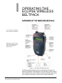
1
ECLIPSE DIGITAL WIRELESS
USER MANUAL
Eclipse Digital Wireless Beltpack Instruction Manual
© 2007, 2009 Vitec Group Communications Ltd. All rights reserved.
Part Number 810376Z Rev. 3
Vitec Group Communications, LLC.
850 Marina Village Parkway
Alameda, CA 94501
U.S.A
Vitec Group Communications Ltd
7400 Beach Drive
IQ Cambridge
Cambridgeshire
United Kingdom
CB25 9TP
The Vitec Group plc
Beijing Representative Office
Room 706, Tower B
Derun Building, YongAn Dongli A No.3
Jianwai Ave., Chaoyang District
Beijing, P.R.China 100022
® Clear-Com, CellCom/FreeSpeak and the Clear-Com Communication Systems logo are registered
trademarks of The Vitec Group plc.
Website: www.clearcom.com
Vitec Group Communications
SOFTWARE LICENSE
IMPORTANT: CAREFULLY READ THE FOLLOWING BEFORE
USING THIS SOFTWARE. USING THE SOFTWARE INDICATES
YOUR ACKNOWLEDGMENT THAT YOU HAVE READ THE
FOLLOWING AND AGREE TO ITS TERMS.
IF YOU DO NOT AGREE, RETURN THE SOFTWARE COMPLETE
TO VITEC GROUP COMMUNICATIONS LIMITED OR CANCEL THE
INSTALLATION.
THIS IS YOUR PROOF THAT YOU HAVE A VALID LICENSE.
PLEASE TREAT IT AS VALUABLE PROPERTY.
VITEC GROUP COMMUNICATIONS LIMITED OR VITEC GROUP
COMMUNICATIONS, INC., as the case may be (hereinafter referred
to as “VGC”), offers you this storage media containing a
computer program and files (the “SOFTWARE”) and offers to
grant to you a non-exclusive and non-transferable License to use
the Software on the following terms. Any new revision or update
of the Software provided by VGC to Customer under this License
shall be governed by the terms and conditions of this License.
1. APPLICATION
a. These terms supersede all prior agreements representations
and understandings between you the Customer and VGC and their
authorised representatives relating to the subject matter hereof
(i.e., the Software) but shall otherwise be subject to Vitec Group
Communications Terms and Conditions, as amended from time to
time. For the avoidance of doubt, in the event of conflict, these
terms shall prevail.
b. No variation to these terms, nor any other terms or conditions
proposed by you, shall be of any effect unless recorded in a written
document signed by VGC. You confirm that any statement made to
the contrary by you or on your behalf shall not apply to this
License.
c. You confirm that you are not relying on any statement made by
or on behalf of VGC, other than statements recorded in a written
document signed by VGC.
d. VGC and its licensors reserve all rights not expressly granted to
you. VGC's licensors are intended third party beneficiaries of this
Agreement and have the express right to rely upon and directly
enforce the terms set forth herein.
e. You agree that the Software belongs to VGC and its licensors.
You agree that you neither own nor hereby acquire any claim or
right of ownership to the Software or to any related patents,
Clear-Com Communication Systems
Eclipse Wireless Communication System
i
copyrights, trademarks or other intellectual property. VGC and its
licensors retain all right, title and interest in and to the Software and
all copies thereof at all times, regardless of the form or media in or
on which the original or other copies may subsequently exist. This
license is not a sale of the original or any subsequent copy.
2. COPYRIGHT
a. The copyright and all other rights in the Software produced by
VGC shall remain with VGC or its suppliers. You must reproduce
any copyright or other notice marked on the Software on any
copies that you make.
3. YOU MAY:
a. Use the Software only at a single site location. If you wish to use
the Software at more than one site you must contact VGC and if
required purchase further Licenses;
b. Make one copy of the Software for archival or back-up purposes,
and;
c. Transfer the Software to an end user of a VGC product, only if
you have made it clear to VGC that you are not the end user and
you assign all of your rights under this License and make no use of
the Software yourself.
4. YOU MAY NOT:
a. Use the Software or make copies of it except as permitted in this
License;
b. Publish or distribute the computer images, sound files or fonts
included with the Software as computer images, sound files or
fonts;
c. Translate, reverse engineer, decompile or disassemble the
Software, except to the extent the foregoing restriction is expressly
prohibited by applicable law;
d. Rent, lease, assign or transfer the Software except as set out
above; or
e. Modify the Software or merge all or any part of the Software in
another program.
5. TERM:
a. This License shall continue for as long as you use the Software.
However, it will terminate if you fail to comply with any of its terms
or conditions. You agree, upon termination, to destroy all copies of
the Software. The Limitations of Warranties and Liability set out
below shall continue in force even after any termination.
6. LIMITED WARRANTY:
a. VGC warrants that the storage media in this Software will be free
from defects in materials and workmanship for 90 days from the
date you acquire it. If such a defect occurs, return it to us at the
address below and we will replace it free. This remedy is your
exclusive remedy for breach of this warranty.
ii
Clear-Com Communication Systems
Eclipse Wireless Communication System
b. After the initial 90 days, THE SOFTWARE IS PROVIDED "AS
IS" WITHOUT WARRANTY OF ANY KIND EITHER EXPRESS,
IMPLIED OR STATUTORY, INCLUDING BUT NOT LIMITED TO
THE IMPLIED WARRANTIES OF MERCHANTABILITY, FITNESS
FOR A PARTICULAR PURPOSE, PERFORMANCE, ACCURACY,
RELIABILITY, OR NON-INFRINGEMENT OF THIRD-PARTY
INTELLECTUAL PROPERTY RIGHTS. This constitutes an
essential part of this License.
7. LIMITATION OF LIABILITY:
a. For the avoidance of doubt, all conditions imposed by law
covering matters such as fitness for purpose, compliance to
description, negligence and quality are expressly excluded
from this agreement and you agree to accept the foregoing
warranty in lieu of all such items.
b. IN NO EVENT SHALL VGC BE LIABLE FOR ANY LOSS OF
PROFITS, LOSS OF BUSINESS, LOSS OF DATA OR USE OF
DATA, INTERRUPTION OF BUSINESS, OR FOR INDIRECT,
SPECIAL, INCIDENTAL, EXEMPLARY, MULTIPLE, PUNITIVE OR
CONSEQUENTIAL DAMAGES OF ANY KIND, WHETHER
BASED ON CONTRACT, TORT (INCLUDING WITHOUT
LIMITATION, NEGLIGENCE), WARRANTY, GUARANTEE OR
ANY OTHER LEGAL OR EQUITABLE GROUNDS, EVEN IF VGC
HAS BEEN ADVISED OF THE POSSIBILITY OF SUCH
DAMAGES.
c. The warranty is personal to you (or end user if you have made it
clear that you are not the end user) and may not be transferred
(except as permitted expressly above).
d. VGC shall not be a liable for failure to perform any obligation to
you where such failure is due to circumstances beyond VGC’s
reasonable control.
e. VGC offers extended warranties and, if you are not satisfied
with the above, you should consider such warranties or
consider separate insurance.
8. RESTRICTED RIGHTS:
If this Software is acquired by or for the U.S. Government then it is provided with Restricted Rights. Use, duplication, or disclosure by the U.S.
Government is subject to restrictions as set forth in subparagraph
(c)(1)(ii) of The Rights in Technical Data and Computer Software clause
at DFARS 252.227-7013, or subparagraphs (c)(1) and (2) of the Commercial Computer Software - Restricted Rights at 48 CFR 52.227-19, or
clause 18-52.227-86(d) of the NASA Supplement to the FAR, as applicable. Contractor/manufacturer: Vitec Group Communications Limited,
7400 Beach Drive, Cambridge, England CB25 9TP or Vitec Group
Communications, LLC., 850 Marina Village Parkway, Alameda, CA
94501.
9. OTHER ISSUES:
a. Any failure by VGC to insist on its strict rights under this
Agreement shall not be deemed to be a waiver of those (or any
Clear-Com Communication Systems
Eclipse Wireless Communication System
iii
other rights) and only a duly executed written release shall
constitute such a waiver.
b. If any of these conditions is deemed invalid or unenforceable the
remainder shall be unaffected.
c. VGC's dealings with you shall be governed by English law if you
are resident in the EMEA region and California law if you are
resident elsewhere. The federal and state courts of California for
Non-EMEA Customers and English Courts for EMEA Customers
shall have exclusive jurisdiction to adjudicate any dispute arising
out of this Agreement.
d. If any document is written in more than one language the
English text shall prevail.
e. Capitalized terms not defined herein shall have the meanings
set forth in Vitec Group Communications' Terms and Conditions, as
amended from time to time.
iv
Clear-Com Communication Systems
Eclipse Wireless Communication System
CONTENTS
OPERATING THE ECLIPSE WIRELESS BELTPACK .
1-1
Overview of the Wireless Belpack . . . . . . . . . . . . . . . . . . . . . . . . . . 1-1
Beltpack Top Control Section . . . . . . . . . . . . . . . . . . . . . . . . . . . . 1-2
Talk Knobs, Channels A and B . . . . . . . . . . . . . . . . . . . . . . . . . 1-3
Level-Control Lights, Channels A and B . . . . . . . . . . . . . . . . . . 1-3
Talk/Listen Lights, Channels A and B . . . . . . . . . . . . . . . . . . . . 1-3
Answer-Back Lights . . . . . . . . . . . . . . . . . . . . . . . . . . . . . . . . . . 1-3
Beltpack Front/Display Section . . . . . . . . . . . . . . . . . . . . . . . . . . . 1-4
Backlit LCD Display . . . . . . . . . . . . . . . . . . . . . . . . . . . . . . . . . . 1-4
Left and Right Scroll Buttons . . . . . . . . . . . . . . . . . . . . . . . . . . . 1-4
Enter/Answer-Back Button. . . . . . . . . . . . . . . . . . . . . . . . . . . . . 1-4
Beltpack Rear/Battery Section . . . . . . . . . . . . . . . . . . . . . . . . . . . 1-5
Power Button . . . . . . . . . . . . . . . . . . . . . . . . . . . . . . . . . . . . . . . 1-5
Battery Case . . . . . . . . . . . . . . . . . . . . . . . . . . . . . . . . . . . . . . . 1-5
Belt Clip . . . . . . . . . . . . . . . . . . . . . . . . . . . . . . . . . . . . . . . . . . . 1-6
Beltpack Bottom Connector Section . . . . . . . . . . . . . . . . . . . . . . . 1-6
Data Connector . . . . . . . . . . . . . . . . . . . . . . . . . . . . . . . . . . . . . 1-6
Headset Connector . . . . . . . . . . . . . . . . . . . . . . . . . . . . . . . . . . 1-6
Battery Recharger Connector . . . . . . . . . . . . . . . . . . . . . . . . . . 1-6
Beltpack Turn-On Sequence . . . . . . . . . . . . . . . . . . . . . . . . . . . . . 1-7
Beltpack Turn-Off Sequence . . . . . . . . . . . . . . . . . . . . . . . . . . . . . 1-7
Powering the Eclipse Beltpack . . . . . . . . . . . . . . . . . . . . . . . . . . . 1-7
Registering Beltpacks with the Matrix . . . . . . . . . . . . . . . . . . . . . . 1-9
Accessing the Talk/Listen Paths on the Eclipse Beltpack . . . . . . . . 1-10
Setting and Adjusting Listen Levels . . . . . . . . . . . . . . . . . . . . . . 1-12
Headset Limiter . . . . . . . . . . . . . . . . . . . . . . . . . . . . . . . . . . . . . . 1-12
Using the Beltpack Answer-Back Functions . . . . . . . . . . . . . . . . 1-13
Beltpack Menu Options. . . . . . . . . . . . . . . . . . . . . . . . . . . . . . . . . . 1-13
Alarm Options . . . . . . . . . . . . . . . . . . . . . . . . . . . . . . . . . . . . . . 1-14
Low Battery Alarm . . . . . . . . . . . . . . . . . . . . . . . . . . . . . . . . . . 1-14
Low Signal Alarm. . . . . . . . . . . . . . . . . . . . . . . . . . . . . . . . . . . 1-14
Audio Options . . . . . . . . . . . . . . . . . . . . . . . . . . . . . . . . . . . . . . . 1-15
Headphone-Off Level Option . . . . . . . . . . . . . . . . . . . . . . . . . . 1-15
Page Lock Option . . . . . . . . . . . . . . . . . . . . . . . . . . . . . . . . . . 1-15
Headphone Limiter Option. . . . . . . . . . . . . . . . . . . . . . . . . . . . 1-15
Microphone Type Option . . . . . . . . . . . . . . . . . . . . . . . . . . . . . 1-15
Microphone Level Option. . . . . . . . . . . . . . . . . . . . . . . . . . . . . 1-15
Clear-Com Communication Systems
Eclipse Wireless Communication System
i
Headset Options . . . . . . . . . . . . . . . . . . . . . . . . . . . . . . . . . . . 1-15
View Status . . . . . . . . . . . . . . . . . . . . . . . . . . . . . . . . . . . . . . . . . 1-16
Role Information . . . . . . . . . . . . . . . . . . . . . . . . . . . . . . . . . . . 1-16
Beltpack Version . . . . . . . . . . . . . . . . . . . . . . . . . . . . . . . . . . . 1-16
Beltpack ID . . . . . . . . . . . . . . . . . . . . . . . . . . . . . . . . . . . . . . . 1-16
RF Carrier Mask . . . . . . . . . . . . . . . . . . . . . . . . . . . . . . . . . . . 1-16
Connection Info . . . . . . . . . . . . . . . . . . . . . . . . . . . . . . . . . . . . 1-16
Adjust Contrast . . . . . . . . . . . . . . . . . . . . . . . . . . . . . . . . . . . . 1-16
PROGRAMMING AT THE BELTPACK . . . . . . . . . . 2-1
Introduction to Programming on the Beltpack. . . . . . . . . . . . . . . . . . 2-1
Selection of Key and Page . . . . . . . . . . . . . . . . . . . . . . . . . . . . . . . . 2-1
Master Volume Control . . . . . . . . . . . . . . . . . . . . . . . . . . . . . . . . . . . 2-2
Beltpack Programming - Menu Map . . . . . . . . . . . . . . . . . . . . . . . . . 2-2
Main Programming Menu . . . . . . . . . . . . . . . . . . . . . . . . . . . . . . . . . 2-2
Top Level Menu. . . . . . . . . . . . . . . . . . . . . . . . . . . . . . . . . . . . . . . 2-3
Settings Menus . . . . . . . . . . . . . . . . . . . . . . . . . . . . . . . . . . . . . . . . . 2-4
The Headphone Menu. . . . . . . . . . . . . . . . . . . . . . . . . . . . . . . . . . 2-5
Headset Noise Gate . . . . . . . . . . . . . . . . . . . . . . . . . . . . . . . . . . . 2-7
Adjust Contrast . . . . . . . . . . . . . . . . . . . . . . . . . . . . . . . . . . . . . . . 2-8
The Alarm Options Menu . . . . . . . . . . . . . . . . . . . . . . . . . . . . . . . 2-8
Switching the Low Battery Alarm ON and OFF . . . . . . . . . . . . . . . 2-9
Low Battery Alarm Off . . . . . . . . . . . . . . . . . . . . . . . . . . . . . . . . 2-9
Low Battery Alarm On1 . . . . . . . . . . . . . . . . . . . . . . . . . . . . . . . 2-9
Low Battery Alarm On2 . . . . . . . . . . . . . . . . . . . . . . . . . . . . . . 2-10
Low Battery Alarm Threshold . . . . . . . . . . . . . . . . . . . . . . . . . 2-10
Low Battery Threshold Setup . . . . . . . . . . . . . . . . . . . . . . . . . 2-10
Switching the Low Signal Strength Alarm ON and OFF . . . . . . . 2-10
The Vibrabeep Call Alert Menu . . . . . . . . . . . . . . . . . . . . . . . . . . 2-11
The Microphone Menu . . . . . . . . . . . . . . . . . . . . . . . . . . . . . . . . 2-12
Set Factory Defaults . . . . . . . . . . . . . . . . . . . . . . . . . . . . . . . . . . 2-13
Button Options Menu . . . . . . . . . . . . . . . . . . . . . . . . . . . . . . . . . . . 2-14
Keylock . . . . . . . . . . . . . . . . . . . . . . . . . . . . . . . . . . . . . . . . . . . . 2-14
Tap Latch. . . . . . . . . . . . . . . . . . . . . . . . . . . . . . . . . . . . . . . . . . . 2-15
PTT Configuration . . . . . . . . . . . . . . . . . . . . . . . . . . . . . . . . . . . . 2-15
The Status (Information) Menu . . . . . . . . . . . . . . . . . . . . . . . . . . . . 2-16
Page Options . . . . . . . . . . . . . . . . . . . . . . . . . . . . . . . . . . . . . . . . . 2-19
Page Locking . . . . . . . . . . . . . . . . . . . . . . . . . . . . . . . . . . . . . . . 2-19
ii
Clear-Com Communication Systems
Eclipse Wireless Communication System
OPERATING THE ECLIPSE TRANSCEIVER/
ANTENNA . . . . . . . . . . . . . . . . . . . . . . . . . . . . . . . . 3-1
Transceiver/Antenna. . . . . . . . . . . . . . . . . . . . . . . . . . . . . . . . . . . . . 3-1
Transceiver/Antenna Top Panel . . . . . . . . . . . . . . . . . . . . . . . . . . 3-1
Omnidirectional Antennas . . . . . . . . . . . . . . . . . . . . . . . . . . . . . 3-1
Transceiver Antenna Bottom/Control Panel . . . . . . . . . . . . . . . . . 3-2
Serial Data Connector . . . . . . . . . . . . . . . . . . . . . . . . . . . . . . . . 3-2
Data Signal LED . . . . . . . . . . . . . . . . . . . . . . . . . . . . . . . . . . . . 3-2
Matrix Connector . . . . . . . . . . . . . . . . . . . . . . . . . . . . . . . . . . . . 3-2
Power LED. . . . . . . . . . . . . . . . . . . . . . . . . . . . . . . . . . . . . . . . . 3-3
DC In Power Connector. . . . . . . . . . . . . . . . . . . . . . . . . . . . . . . 3-3
Cabling the Transceiver/Antennas . . . . . . . . . . . . . . . . . . . . . . . . 3-3
Beltpack Support Capacities for Transceiver/Antennas . . . . . . . . 3-3
Coverage Areas Under Various Conditions. . . . . . . . . . . . . . . . . . 3-4
Transceiver/Antenna Setup Rules and Tips . . . . . . . . . . . . . . . . . 3-4
Transceiver/Antenna Splitter. . . . . . . . . . . . . . . . . . . . . . . . . . . . . . . 3-5
Splitter Front Connector Panel . . . . . . . . . . . . . . . . . . . . . . . . . . . 3-5
Base Connection Indicator Light . . . . . . . . . . . . . . . . . . . . . . . . 3-5
Matrix (Eclipse Base) Connector . . . . . . . . . . . . . . . . . . . . . . . . 3-6
Splitter-to-Transceiver/Antenna Signal Indicator Light . . . . . . . 3-6
Transceiver/Antenna Connectors . . . . . . . . . . . . . . . . . . . . . . . 3-6
Splitter Rear Panel . . . . . . . . . . . . . . . . . . . . . . . . . . . . . . . . . . . . 3-6
Serial Data Connector . . . . . . . . . . . . . . . . . . . . . . . . . . . . . . . . 3-6
Power Indicator . . . . . . . . . . . . . . . . . . . . . . . . . . . . . . . . . . . . . 3-6
DC IN Power Connector . . . . . . . . . . . . . . . . . . . . . . . . . . . . . . 3-7
EXP IN Connector . . . . . . . . . . . . . . . . . . . . . . . . . . . . . . . . . . . 3-7
EXP OUT Connector . . . . . . . . . . . . . . . . . . . . . . . . . . . . . . . . . 3-7
Connecting an Antenna Splitter to the Eclipse Base and to Transceiver/Antennas . . . . . . . . . . . . . . . . . . . . . . . . . . . . . . . . . . . . . . . . 3-7
INSTALLING A SYSTEM. . . . . . . . . . . . . . . . . . . . . 4-1
Placing the Matrix . . . . . . . . . . . . . . . . . . . . . . . . . . . . . . . . . . . . . . . 4-1
Placing the Antennas and Splitters . . . . . . . . . . . . . . . . . . . . . . . . . . 4-1
Wiring the Antennas and Splitters . . . . . . . . . . . . . . . . . . . . . . . . . 4-2
Determining Coverage Areas . . . . . . . . . . . . . . . . . . . . . . . . . . . . 4-2
Doing a Site Survey to Determine Coverage Areas . . . . . . . . . . . . . 4-3
Testing Coverage Areas of Individual Antennas . . . . . . . . . . . . . . 4-3
Testing Antenna Handoff . . . . . . . . . . . . . . . . . . . . . . . . . . . . . . . . 4-5
Assigning Beltpacks to Coverage Areas . . . . . . . . . . . . . . . . . . . . 4-6
Conditions Affecting Coverage Areas . . . . . . . . . . . . . . . . . . . . . . 4-6
Clear-Com Communication Systems
Eclipse Wireless Communication System
iii
SPECIFICATIONS . . . . . . . . . . . . . . . . . . . . . . . . . . 5-1
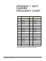
APPENDIX 1: DECT CARRIER FREQUENCY CHART
6-1
GLOSSARY . . . . . . . . . . . . . . . . . . . . . . . . . . . . . . . 7-1
Eclipse Manuals . . . . . . . . . . . . . . . . . . . . . . . . . . . . . . . . . . . . . . . . 7-5
Software Manuals . . . . . . . . . . . . . . . . . . . . . . . . . . . . . . . . . . . . . 7-5
Hardware Manuals . . . . . . . . . . . . . . . . . . . . . . . . . . . . . . . . . . . . 7-5
LIMITED WARRANTY . . . . . . . . . . . . . . . . . . . . . . . W-I
TECHNICAL SUPPORT & REPAIR POLICY. . . . . W-V
TECHNICAL SUPPORT POLICY . . . . . . . . . . . . . . . . . . . . . . . . . . W-v
RETURN MATERIAL AUTHORIZATION POLICY . . . . . . . . . . . . . W-vi
REPAIR POLICY . . . . . . . . . . . . . . . . . . . . . . . . . . . . . . . . . . . . . W-viii
iv
Clear-Com Communication Systems
Eclipse Wireless Communication System
FIGURES
Figure 1-1 Overview of Beltpack Functions ..................................... 1-1
Figure 1-2 Beltpack Display............................................................. 1-2
Figure 1-3 View of Top of Beltpack.................................................. 1-2
Figure 1-4 View of Front of Beltpack ............................................... 1-4
Figure 1-5 View of Back of Beltpack................................................ 1-5
Figure 1-6 View of Bottom of Beltpack ............................................ 1-6
Figure 1-7 Battery Discharge Characteristics .................................. 1-8
Figure 1-8 How the beltpack displays its six communication routes......
1-11
Figure 2-1 Top Level Menu Structure .............................................. 2-3
Figure 2-2 Beltpack Settings Menu Structure .................................. 2-5
Figure 2-3 Connection Information Display ................................... 2-18
Figure 3-1 Eclipse Transceiver/Antenna.......................................... 3-1
Figure 3-2 Eclipse Transceiver/Antenna Bottom/Control Panel ...... 3-2
Figure 3-3 Eclipse Splitter Front Connector Panel .......................... 3-5
Figure 4-1 A Beltpack’s Site Survey Screen.................................... 4-4
Figure 4-2 Mapping overlapping coverage zones............................ 4-5
Clear-Com Communication Systems
Eclipse Wireless Communication System
i
ii
Clear-Com Communication Systems
Eclipse Wireless Communication System
TABLES
Beltpack Programming Serial Cable Pinout ..................................... 1-9
Connection Information .................................................................. 2-18
How antennas are numbered .......................................................... 4-6
DECT Carrier Frequency Chart ....................................................... 6-1
Clear-Com Communication Systems
Eclipse Wireless Communication System
i
ii
Clear-Com Communication Systems
Eclipse Wireless Communication System
IMPORTANT SAFETY
INSTRUCTIONS
Please read and follow these instructions before operating an Eclipse wireless
communication system. Keep these instructions for future reference.
(1) WARNING: To reduce the risk of fire or electric shock, do not
expose this apparatus to rain or moisture.
(2) Do not use the apparatus near water.
Please read and follow these
instructions before operating
a CellCom wireless
communication system.
(3) Clean only with a dry cloth.
(4) Do not block any ventilation openings. Install in accordance
with the manufacturer’s instructions. Install the CellCom wireless
communication system according to the directions in the
Installation Chapter of this manual.
(5) Do not install near any heat sources such as radiators, heat
registers, stoves, or other apparatus (including amplifiers) that
produce heat. Do not place naked flame sources such as candles
on or near the matrix.
(6) Do not defeat the safety purpose of the polarized plug or
grounding-type plug. A polarized plug has two blades with one
wider than the other. A grounding-type plug has two blades and a
third grounding prong. The wide blade or the third prong are
provided for your safety. If the provided plug does not fit into your
outlet, consult an electrician for replacement of the obsolete
outlet.
(7) Protect power leads from being walked on or pinched
particularly at plugs, at convenience receptacles, and at the point
where they exit from the apparatus.
Note: A “convenience receptacle” is an extra AC power outlet
located on the back of a piece of equipment, intended to allow
you to power other equipment.
(8) Only use attachments/accessories specified by the
manufacturer.
(9) Use only with the cart, stand, tripod, bracket, or table specified
by the manufacturer, or sold with the apparatus. When a cart is
used, use caution when moving the cart/apparatus combination
to avoid injury from tip-over.
(10) Unplug the apparatus during lightning storms or when
unused for long periods of time.
(11) Refer all servicing to qualified service personnel. Servicing is
required when the apparatus has been damaged in any way, such
Clear-Com Communication Systems
Eclipse Wireless Communication System
iii
as a power-supply cord or plug is damaged, liquid has been
spilled or objects have fallen into the apparatus, the apparatus
has been exposed to rain or moisture, does not operate normally,
or has been dropped.
(12) The CellCom wireless communication system contains a
non-user serviceable battery.
CAUTION: Danger of explosion if battery is incorrectly replaced.
Replace only with the same or equivalent type.
Lithium batteries can overheat or explode if they are shorted.
When you handle the CPU card or a loose battery, DO NOT touch
any external electrical conductors to the battery’s terminals or to
the circuits that the terminals are connected to.
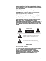
Please familiarize yourself with the safety symbols in Figure 1.
When you see these symbols on a CellCom wireless
communication system, they warn you of the potential danger of
electric shock if the system is used improperly. They also refer
you to important operating and maintenance instructions in the
manual.
CAUTION
RISK OF ELECTRIC SHOCK
DO NOT OPEN
This symbol alerts you to the presence of uninsulated dangerous
voltage within the product’s enclosure that might be of sufficient
magnitude to constitute a risk of electric shock. Do not open
the product’s case.
This symbol informs you that important operating and maintenance instructions are included in the literature accompanying
this product.
Safety Symbols
EMC AND SAFETY
The Eclipse wireless communication system meets all relevant
CE, FCC, UL, and CSA specifications set out below:
EN55103-1 Electromagnetic compatibility. Product family
standard for audio, video, audio-visual, and entertainment
lighting control apparatus for professional use. Part 1:
Emissions.
iv
Clear-Com Communication Systems
Eclipse Wireless Communication System
EN55103-2 Electromagnetic compatibility. Product family
standard for audio, video, audio-visual, and entertainment
lighting control apparatus for professional use. Part 2: Immunity.
UL 60065-7, CAN/CSA-C22.2 No.60065-3, IEC 60065-7 Safety
requirements.
And thereby compliance with the requirement of Electromagnetic
Compatibility Directive 2004/108/EC and Low Voltage Directive
2006/95/EC
This device complies with Part 15 of the FCC Rules. Operation is
subject to the following two conditions: (1) this device may not
cause harmful interference, and (2) this device must accept any
interference received, including interference that may cause
undesired operation.
Clear-Com Communication Systems
Eclipse Wireless Communication System
v
vi
Clear-Com Communication Systems
Eclipse Wireless Communication System
1
OPERATING THE
ECLIPSE WIRELESS
BELTPACK
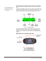
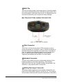
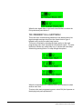
OVERVIEW OF THE WIRELESS BELPACK
You can access six separate
audio routes from a beltpack.
Depress the channel A or B
talk button to select an audio
route. Turn the button to
adjust volume.
Figure 1-1: Overview of Beltpack Functions
An Eclipse wireless beltpack gives you simultaneous access to six
channels of talk/listen communication, with the ability to switch among
them as desired. Any or all of these six routes may be kept open during
use. Incoming volume levels (“listen levels”) may be individually
Clear-Com Communication Systems
Eclipse Wireless Communication System
1-1
Any or all of the beltpack’s six
audio routes may be kept
open while you talk or listen
on the beltpack.
adjusted using the two push-to-talk knobs, so that one conversation
can be monitored in the background while a primary conversation is
held.
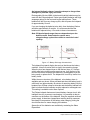
The front-panel display contains the name (label) of the beltpack user,
identifies the two talk/listen labels currently selected by the user, and
gives other information such as signal strength and battery level.
Figure 1-2: Beltpack Display
A 4-pin male headset connector is provided for connection with a
standard Clear-Com headset or similar. The Eclipse beltpack will
operate for up to 8 hours on four AA alkaline or rechargeable NiMH
batteries.
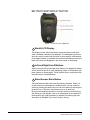
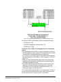
BELTPACK TOP CONTROL SECTION
Figure 1-3: View of Top of Beltpack
1-2
Clear-Com Communication Systems
Eclipse Wireless Communication System
1 Talk Knobs, Channels A and B
The talk knob functions as a volume control for incoming audio
assigned to channels A and B. Turn the knob clockwise to increase the
volume, and counterclockwise to decrease it.
To talk or listen on a channel, press and hold the knob down while
speaking or listening from the headset. While you hold the knob down,
your voice transmits on that channel. When you release the knob, your
voice no longer transmits.
To “latch” a knob “on” for hands-free use, quickly tap the knob. Another
quick tap releases the latch.
2 Level-Control Lights, Channels A and B
Three level-control lights are located next to each talk knob. The first
light is green, the second is yellow, and the third is red. With the knob
turned fully counterclockwise, only the green LED is lit to indicate low
volume. Turning the knob clockwise, low audio level is heard in the
headset. Turning the knob more, both the green and yellow LED’s
light, and higher audio level is heard. This continues through the
maximum audio level, indicated by only the red light being lit.
3 Talk/Listen Lights, Channels A and B
The green “listen” light blinks whenever a beltpack receives audio from
a source whose label is displayed on the beltpack’s LED screen. When
you press the talk button to “talk,” the green light then illuminates
steadily and the red light also illuminates.
4 Answer-Back Lights
The green and red lights labeled “answer” illuminate when a source
who is not on the beltpack’s presently selected communication routes
tries to initiate a call to the beltpack. The red light flashes when a call
is coming in and when the beltpack is communicating.
By pressing the answer-back button on the front of the beltpack you
can answer an incoming call. The green LED then lights steadily and
the red LED flashes until the conversation is ended by again pushing
the answer-back button.
Clear-Com Communication Systems
Eclipse Wireless Communication System
1-3
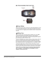
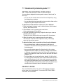
BELTPACK FRONT/DISPLAY SECTION
Figure 1-4: View of Front of Beltpack
1 Backlit LCD Display
The display screen shows the various communications routes and
other information relevant to the beltpack. The backlighting comes on
when any action is taken with the scroll or enter buttons, and remains
on for approximately 10 seconds. During the answer-back process, the
label of the source is displayed in the lower center of the display.
2 Left and Right Scroll Buttons
When you press the left and right scroll buttons, the beltpack’s display
screen scrolls to the left or right, displaying “pages” of information, and
menu options on those pages. These buttons work in conjunction with
the enter button, described below.
3 Enter/Answer-Back Button
The enter/answer-back button has two primary purposes. When you
view the menus on the beltpack’s display screen, you can select an
option by pressing this button and you can exit a menu by selecting the
up-arrow icon. In this way, the button serves as an enter key.
During normal beltpack operation it functions as the answer-back key,
with which you can activate a talk to an unassigned source when the
answer-back “talk” light illuminates to indicate an incoming call (see
description in “Beltpack Top Control Section” above).
1-4
Clear-Com Communication Systems
Eclipse Wireless Communication System
BELTPACK REAR/BATTERY SECTION
Figure 1-5: View of Back of Beltpack
1 Power Button
The recessed power button is used to turn the Eclipse beltpack on and
off. Press and hold the button for about three seconds to turn the unit
on. To turn the unit off, again press and hold the button for about three
seconds.
2 Battery Case
The removable battery case will hold four alkaline AA or four NiMH
(nickel-metal hydride) rechargeable batteries. These batteries
alternate, with the negative pole contacting the spring and the positive
pole contacting the plate inside the case.
To remove the battery case, press on the top of the belt clip to lift it off
the case, and with the thumb and middle or ring finger of the other
hand squeeze the side tabs of the case and lift it out, slightly tilting the
lower (toward the bottom of the beltpack) portion of the pack out first.
To insert the battery pack, follow the above instructions in reverse.
Note that the battery case has a clip-on lower cover; make sure to put
it back in place before putting the battery case back into the beltpack.
Caution: Do not put battery packs containing alkaline batteries
into a recharger, or recharge them in the beltpack. Serious
damage or injury could result.
Clear-Com Communication Systems
Eclipse Wireless Communication System
1-5
3 Belt Clip
The belt clip is spring-loaded, with enough tension to hold the beltpack
to the user’s belt and against the hip. Note that the upper portion of the
rear of the beltpack, connected to the belt clip, is a separate piece; the
entire belt clip assembly may be replaced in case of damage.
BELTPACK BOTTOM CONNECTOR SECTION
Figure 1-6: View of Bottom of Beltpack
1 Data Connector
This 3.5 mm (1/8 inch) tip-ring-sleeve (TRS) connector is used to
connect the beltpack to a computer in order to identify the beltpack to
the matrix during initial registration and system setup. It may also be
used if an upgrade to the beltpack firmware is ever required in the
future, to add new features and capabilities. See the section
“Registering the Beltpack with the Matrix” for further details.
2 Headset Connector
The male 4-pin headset connector provides audio pathways for the
headset microphone and headset earpiece(s). This connector
supports all Clear-Com and compatible headsets using female 4-pin
connectors. It will support dynamic microphones.
3 Battery Recharger Connector
The Eclipse beltpack features an internal battery charger when you
insert four AA-format NiMH batteries to power the unit. The recharger
circuit includes a thermistor that senses the temperature of the battery
1-6
Clear-Com Communication Systems
Eclipse Wireless Communication System
pack to prevent overcharging. To use this internal recharger, plug in
the small barrel connector on the supplied universal power supply into
the beltpack connector, and then plug the supply into the local AC
current. The beltpack will automatically shut off when the charging
PSU is plugged into it. While it is charging, the beltpack cannot be
turned on. You can only turn it on when the charging PSU is
disconnected. A full charge takes approximately 3 to 4 hours
depending on the battery capacity. After this time, the charger will
maintain a trickle charge to keep the beltpack fully charged.
Eclipse beltpack usage time is dependent upon the batteries used.
Some batteries require more charge/discharge cycles than others to
reach their rated capacity.
Caution: Do not put battery packs containing alkaline batteries
into a recharger, or recharge them in the beltpack. Serious
damage or injury could result.
BELTPACK TURN-ON SEQUENCE
After pressing the POWER button on the rear of the beltpack for
approximately three seconds, the top control panel LEDs will flash and
the display will light. The display will say “CLearCom” and
“Searching...” It will briefly say “Getting Roles,” and then will go to the
main user screen.
The beltpack will always begin on page 1, which has the first two
communication routes assigned to the beltpack. When programming
communication routes for the users in the system, it is best to put the
most commonly used ones on this page.
BELTPACK TURN-OFF SEQUENCE
To turn off the beltpack, press and hold the POWER button on the rear
of the beltpack for about three seconds. The main screen will close,
followed by a screen that says “CLearCom” and “Shutting Down.”
POWERING THE ECLIPSE BELTPACK
The supplied battery pack holds four AA-sized batteries. Standard AA
alkaline batteries will provide between 7 and 8 hours of typical use.
The batteries alternate in the battery case, with the spring on the
negative end and the tab on the positive end.
For best performance, use fresh alkaline batteries that have been
properly stored and kept away from excessive heat. As with all other
battery-powered electronic items, when the Eclipse beltpack is stored
for extended periods of time, remove the batteries to prevent damage
from possible leakage of the alkaline cells.
Caution: Make sure that Eclipse beltpack battery packs loaded
with alkaline batteries are not put into a battery charger, or that
Clear-Com Communication Systems
Eclipse Wireless Communication System
1-7
the internal beltpack charger is used to attempt to charge them.
Damage and possible injury will result.
Rechargeable AA-size NiMH (nickel-metal hydride) batteries may be
used with the Eclipse beltpack. Select good quality batteries with high
amperage ratings for the best and longest performance. These
batteries will last for many charge cycles, and will power the beltpack
for approximately 8 hours.
If you are charging the batteries twice daily, then the battery lifetime
would be approximately 8 months. It is recommended that the
batteries be replaced every 4-5 months in these circumstances.
Note: Eclipse beltpack usage times are dependent upon the
batteries used. Some batteries require more
charge/recharge cycles than others to reach their rated
capacity.
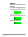
Figure 1-7: Battery Discharge Characteristics
The beltpack front-panel display has an icon that shows the battery
condition. It has five vertical lines to signify the remaining charge.
When the icon has dropped down to the last two lines, or if it drops
quickly after being turned on after previous use, it will be time in the
next few minutes to recharge the batteries (if rechargeable ones are
being used) or replace them. The beltpack will turn off by itself at low
battery levels.
Within the menu structure of the beltpack, a low-battery alarm is
available and may be set. When activated and when the battery level is
sufficiently low (approximately 40 minutes of remaining battery life) the
headset user will hear a beep at intervals and the battery indicator will
flash to indicate that the batteries must be replaced or recharged soon.
This setting is available under Alarm Options.
The Eclipse beltpack features an internal battery charger circuit, with
intelligent circuitry to prevent overcharging. It is powered via the pin
connector on the bottom of the beltpack, using the supplied universal
power supply. A thermistor (temperature-sensing device) measures
the change in temperature of the battery when charging, letting the
circuit know when to cease charging the batteries.
Spare clips of four batteries are available by contacting the Sales
Department.
1-8
Clear-Com Communication Systems
Eclipse Wireless Communication System
REGISTERING BELTPACKS WITH THE MATRIX
The PC-to-Beltpack serial cable is used to register beltpacks with the
PC running the Eclipse Configuration Software (ECS). It can also be
used to upgrade the firmware of the beltpacks. The beltpacks are
registered from the ‘Beltpacks’ tab in ECS (‘Beltpacks’ link in the Setup
menu). Click on the ‘Beltpacks’ link to open the tab, click on the
‘Register’ button and follow the beltpack registration instructions
displayed.
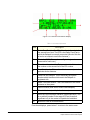
The cable consists of a female 9-pin D type connector (PC connection)
and a 3.5 mm (1.8-inch) stereo jack plug (beltpack connection). Care
must be taken to select a jack plug that fits completely through the
plastic surround of the connector at the bottom of the beltpack.
The data connections between the D connector and the stereo jack
plug are as follows: pin 2 to tip, pin 3 to ring, and pin 5 to sleeve. Pins
1,4,6 and 8 on the PC connector are shorted together.
PC Connection usually 9 way
Female D-type connector
Beltpack connection 3.5mm Stereo
jack plug
1
2
3
4
5
6
7
8
9
N/C
Tip
Ring
N/C
Screen
N/C
N/C
N/C
N/C
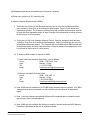
Table 1-1: Beltpack Programming Serial Cable Pinout
Clear-Com Communication Systems
Eclipse Wireless Communication System
1-9
ACCESSING THE TALK/LISTEN PATHS ON
THE ECLIPSE BELTPACK
You can access up to twelve communications routes with a beltpack.
You activate a route by pressing the appropriate talk button (A or B)
when the desired label appears on the beltpack’s display.
• Page 1 of the beltpack’s display screen shows the assignments for
the Talk A and Talk B buttons (2 assignments).
• Page two shows the next set of assignments for the Talk A and
Talk B buttons (2 assignments).
• Page three shows the next set of assignments for the Talk A and
Talk B knobs (2 assignments).
• Page four shows the next set of assignments for the Talk A and
Talk B knobs (2 assignments).
• Page five shows the next set of assignments for the Talk A and
Talk B knobs (2 assignments).
• Page six shows the next set of assignments for the Talk A and Talk
B knobs (2 assignments).
Figure 1-8 shows how the front-panel screen on a beltpack displays
its six communications routes.
1-10
Clear-Com Communication Systems
Eclipse Wireless Communication System
Figure 1-8: How the beltpack displays its six communication routes
The case of a label on the beltpack indicates its assignment type:
• All uppercase - Talk
• First letter in uppercase, rest lowercase - DTL
• All lowercase - Listen
To activate a talk or listen to an assigned source or destination
(“label”):
1. Use the beltpack’s scroll buttons to scroll to the page on which the
desired assignment (“label”) appears. The beltpack holds six pages
of assignments. Each page displays two assignments.
As you scroll, you will hear “beeps” in the headset that correspond to
the page displaying on the beltpack: 1 beep for page 1, 2 beeps for
page 2, etc.
2. When you reach the appropriate page, select one or both of the
assignments on that page by depressing the corresponding talk
buttons on the beltpack (A or B).
3. Press and hold the appropriate talk button to talk or listen to the
destination. Release the button to close the talk or listen path.
Alternatively, you can quickly tap the talk button to latch it “on.”
Quickly tap it again to release the latch.
4. To activate another communication route, repeat steps 1 through 6.
You can keep all six communication routes “open” at the same time.
You will hear all activity on these routes in your headset.
Clear-Com Communication Systems
Eclipse Wireless Communication System
1-11
Note: Two-wire and four-wire devices can have dual
talk-and-listen or just listen assignments.
SETTING AND ADJUSTING LISTEN LEVELS
You can adjust a beltpack’s incoming audio volume (“listen level”) in
two ways:
• You can set the overall maximum level for the beltpack by using
the beltpack menu options.
• You can adjust the incoming audio level as you talk or listen on the
beltpack using the beltpack’s talk buttons.
To adjust the overall maximum “listen level” for a beltpack:
1. From the beltpack’s display, scroll to Audio Options, then Headset
Options, then Master Level.
2. Select Master Level by pressing the enter button.
A bar graph appears on the display.
3. Using the right and left scroll keys, adjust the level up or down as
desired on the bar graph.
Typically, the level control will be set to around 2/3 of maximum.
4. When the desired level is reached, press the enter button.
That selection is saved in the beltpack’s memory. The display
returns to the previous screen.
To adjust the listen level as you talk or listen from the beltpack:
• As you talk and listen, rotate an assignment’s talk button to
increase or decrease the incoming volume level (“listen level”) for
that assignment.
• As you scroll between pages, the listen levels for the various
assignments remain intact. For example, rotating the talk button
to increase or decrease the listen level for the first assignment on
page 2 will not affect the listen level set with the same talk button
on page 1 or 3.
• The three lights next to each talk button, labeled “Vol A” and Vol
B,” show you the current listen level. At the lowest audio level, the
green light illuminates. As the listen level increases to moderate,
the yellow light illuminates, and as it increases to maximum, the
red light illuminates. Note that the position of the talk button does
not affect the level that is heard or indicated by the lights.
HEADSET LIMITER
The overall headset volume may also be affected by the headset
limiter value set on the beltpack. See section “BELTPACK MENU
OPTIONS” for more details.
1-12
Clear-Com Communication Systems
Eclipse Wireless Communication System
USING THE BELTPACK ANSWER-BACK FUNCTIONS
A beltpack’s “answer-back” key performs two functions:
The first function is to answer a call from a source whose “label”
does not appear on the currently selected beltpack page.
When a source whose label does not appear on the currently selected
beltpack page, but whose label does appear on a non-selected page,
your beltpack’s “answer-back” light flashes, and you can hear the
caller’s voice in your headset at whatever incoming volume you
previously set for that label.
You can answer this call in one of two ways:
• Press the front-panel “answer-back” button on your beltpack. This
establishes a return talk path to the calling beltpack. You can
press and hold the button to talk or you can quickly tap the button
to “latch” it on.
• Use the front-panel scroll buttons to scroll to the page where the
source’s label appears and press the appropriate talk button as
usual.
The second function is to call a beltpack even though it does not
have your “label” assigned to it. You must have assigned the
destination beltpack’s “label” to your beltpack however to make
this type of call.
For example, a stage manager labeled “STMGR” has a lighting crew
member’s label “LGT1” assigned to his beltpack. However, the lighting
crew member does not have the stage manager’s label assigned to his
beltpack.
The stage manager can call the lighting crew member in the usual way.
The lighting crew member can answer the call with the “answer-back”
button on his beltpack and establish a private conversation. The
lighting crew member cannot however initiate a direct call back to the
stage manager.
BELTPACK MENU OPTIONS
The Eclipse beltpack presents you with a number of adjustable
parameters. The main categories of the adjustments are: Alarm
Options, Audio Options, View Status, and Adjust Contrast accessed
through the menu. To enter menu mode hold down both page buttons
simultaneously until the beltpack enters menu mode (about 5
seconds).
An icon of an upward pointing arrow designates EXIT or BACK, and is
available on each menu page. Selecting this icon and pressing the
center ENTER button takes you to the previous screen or exits to the
beltpack’s main menu.
Clear-Com Communication Systems
Eclipse Wireless Communication System
1-13
ALARM OPTIONS
Low Battery Alarm
The low-battery alarm has two settings: on and off. Using the scroll
keys, select the desired setting and then press the center ENTER key.
• When you select ON, you will hear a beep at intervals in your
headset to indicate that it is time to replace or recharge the
belpack batteries. This will occur when the battery level is
sufficiently low (approximately 40 minutes of remaining battery
life). The battery indicator will also flash.
• When you select OFF, you will not be warned of low battery level.
Low Signal Alarm
The low-signal alarm has two settings: on and off. Using the scroll
keys, select the desired setting and then press the center ENTER key.
• When you select ON, you will hear a beeping in the beltpack’s
headset when the beltpack is almost out of the range of the
antenna, and will soon lose connection with the system.
• When the beltpack’s signal-level icon is at the second-lowest
increment, you will hear one quick beep and two slightly longer
beeps at approximately one-second intervals in the headset. You
will hear the same beeps when you go completely out of range
and connection is lost with the antenna (and the base). These
beeps continue until you move into an area where the signal is
stronger.
• This setting may be especially useful when you are learning to
establish the coverage area for a particular location. Because the
signal level when the alarm is first activated is still strong enough
for conversations to happen (though possibly with occasional
audio dropouts), it may not be desirable to keep this alarm on
during normal operation of the system. This low signal alarm is
also useful for checking out the coverage in a location when first
setting up transceiver/antennas, for either a temporary or
permanent installation.
• When you select OFF, the low signal alarm does not operate.
1-14
Clear-Com Communication Systems
Eclipse Wireless Communication System
AUDIO OPTIONS
Headphone-Off Level Option
This option allows you to select the signal threshold when the
headphone audio “turns off.” Level settings are - 6, -12, -18, and – 70
dB. The typical setting is –70 dB, which functions as “always on.”
Page Lock Option
When you select the Page Lock option the page change keys no
longer operate.
Headphone Limiter Option
This option introduces a limiter into to headphone audio circuitry, to
control excessive levels and resulting stress on the ear of the user.
The level can be set anywhere in the range -32dBu to +16dBu using
the Headphone Limiter display on the beltpack. The typical setting is
–6dBu.
Microphone Type Option
This option allows you to select the proper setting for the headset
microphone. The available settings are Dynamic (Balanced) Mic and
Dynamic (Unbalanced) Mic. For most Clear-Com and other headsets,
the Dynamic (Unbal) Mic setting is proper.
Microphone Level Option
This option allows you to set the level of the beltpack’s headset mic,
increasing or decreasing its gain going into the system. For Type I
beltpacks the gain settings are 40, 50, and 60dB, for Type II beltpacks
the gain settings are 50, 55, 60 and 65dB. The typical setting is 50dB.
Headset Options
Two headset options are offered:
• Master Level
• Sidetone Level
The Master Level control accesses a slide bar going from “-“to “+”, and
controls the overall maximum level that can be heard through the
headphones. This gain control permits adjustment among headsets
with different sensitivities, and for different use conditions (quiet studio
versus loud live performance environment). Typical setting is 2/3 to 3/4
of the way toward “+”.
Sidetone Level controls the amount of the user’s own voice (local
sidetone) that is injected into the headphone from the headset mic. It is
activated when you push a talk button or an answer-back key, to let
Clear-Com Communication Systems
Eclipse Wireless Communication System
1-15
you know that the microphone is on. If you do not push a talk button,
you do not hear sidetone.
VIEW STATUS
Role Information
Role Information gives the label (user name) that has been assigned to
the particular beltpack, and also gives a numerical Role Number which
the system uses – typically starting with 700 for the first beltpack and
going up from there.
Beltpack Version
Beltpack Version gives the current software version on the beltpack,
and a CRC number. Use these numbers to determine whether a
beltpack contains the latest software version, and to confirm the
success of a software upgrade.
Beltpack ID
Beltpack ID, also known as IPEI, gives the unique identification
number for the transceiver in the Eclipse beltpack.
RF Carrier Mask
The RF carrier mask tells the matrix and beltpacks which of the
standard DECT carrier frequencies to use. In Europe, for example, the
standard carriers 0 to 9 (1880 to 1900 MHz) are designated as
“0x03FF000000.” Other parts of the world, such as South America, use
Extended Carriers, such as 18 to 27 (1910 to 1930 MHz), designated
as “0x0000007FE0.” The DECT stacks in both the transceiver/antenna
and the beltpack must be told which group of 10 carrier frequencies to
use via the “mask,” when they are first initialized.
Connection Info
Connection Information defines all of the various DECT information for
the beltpack transmission and link to the transceiver/antenna. It also
gives the Carrier Number and Slot that the beltpack is currently using
(this can dynamically change as needed during use). In addition, the
Received Signal Strength Indication (RSSI) is numerically indicated,
with 55 being the highest value; also, the error percentage is shown.
Adjust Contrast
Adjust Contrast provides a slide bar going from “-“to “+”, allowing the
user to adjust the contrast on the display. Typical range is between 1/2
and 3/4 toward “+”.
1-16
Clear-Com Communication Systems
Eclipse Wireless Communication System
2
PROGRAMMING AT
THE BELTPACK
INTRODUCTION TO PROGRAMMING ON THE
BELTPACK
In programming the Beltpack, the general considerations are:
• It is necessary to have a radio connection to be able to engage
programming mode. It is not generally possible to enter
programming mode unless the normal working display is present.
• To access the main programming menu, hold both the UP and
DOWN keys pressed together for at least 3 seconds. This calls up
the main programming menu.
• The Beltpack saves programming data when you press enter on a
menu which does not have an UP arrow at the right hand end. To
exit without saving, press the UP and DOWN buttons
simultaneously for 3 seconds.
• Generally buttons auto-repeat when held pressed.
• The "cursor" is the highlighted item and it cycles round to the other
end of the menu when it reaches one end.
• The icon shown in a box is the currently selected item.
• If the right hand end of the menu contains an UP arrow, selecting
this and pressing Enter will take you back up one level in the
menu structure and will eventually return you to the main working
display.
• The backlight times out after 15 seconds.
The menus in Program Mode are presented graphically as a menu
map. The screen pictures shown in this document refer to beltpacks
running V4A or later of the firmware. Beltpacks with different versions
of the firmware may display slightly different screens.
SELECTION OF KEY AND PAGE
Several areas of the programming set up a mode or function on a
particular key. It is, therefore, necessary to select both the key and the
page on which it appears prior to entering the required programming
menu. The ‘Select Assignment’ display (below)
Clear-Com Communication Systems
Eclipse Wireless Communication System
2-1
is used to select the key and appears whenever a key selection is
required. The page which appears is the one which was current when
programming mode was entered.
If, having entered programming mode, you find that the required key is
not on the page which is displayed, go to the page selection menu.
This indicates (and puts the cursor on to) the page number which was
selected. It also offers the facility to change the current page number if
necessary.
To see both the page number and its content simultaneously, go to
normal operation as described in the operational information.
MASTER VOLUME CONTROL
The master volume control is set from the main page. The scroll
buttons will change the current page if pressed momentarily but if
pressed and held will change the volume setting.
Press and hold one of the scroll buttons until volume bars change then
use the scroll buttons to adjust the master volume as indicated by the
volume bars until the required level is reached.
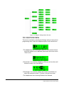
BELTPACK PROGRAMMING - MENU MAP
On the menu map below, the flow is downwards and to the right unless
indicated otherwise.
MAIN PROGRAMMING MENU
This is the main menu for programming the Beltpack.
You reached this menu by holding both the UP and DOWN keys
pressed for at least 3 seconds. To return to normal operation, select
Exit (the Up arrow on the display) and press pushbutton C.
To navigate around any menu, use the UP and DOWN scroll buttons to
highlight the required item (the highlighted item is shown in inverse
video). Then press Pushbutton C (effectively the “Reply/Answerback”
key in normal mode or "Enter" key when in Program Mode) to
implement the selection.
2-2
Clear-Com Communication Systems
Eclipse Wireless Communication System
TOP LEVEL MENU
The top level menu structure is displayed when the scroll keys are held
down as described above.
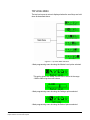
Figure 2-1: Top Level Menu Structure
• Main programming menu showing the Master Level option selected.
This option allows the master volume level to be set in the range
-12dB to 0dB using the scroll buttons.
• Main programming menu showing the Settings option selected.
• Main programming menu showing the Button Options selected.
Clear-Com Communication Systems
Eclipse Wireless Communication System
2-3
• Main programming menu showing the Information (Status) option
selected.
• Main programming menu showing the Page Options selected.
• Main programming menu showing the Exit (from Program mode to
normal operation) option selected.
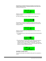
SETTINGS MENUS
The settings menus allow access to most of the beltpack configuration
options. The basic menu structure is given in the figure below.
2-4
Clear-Com Communication Systems
Eclipse Wireless Communication System
Figure 2-2: Beltpack Settings Menu Structure
THE HEADPHONE MENU
This menu is reached by selecting the Settings option on the top level
programming menu, then the headphone options on the audio menu.
• The Headphones menu showing the option to set the lowest level to
which the headset can be adjusted (sometimes also known as the
"Gate Level").
• Press button C to select the Headphone Off menu and use the scroll
buttons to select one of the settings.
• Press button C to select the setting, then use the scroll buttons to
select Exit and press button C to return to the previous menu.
• The Headphones menu showing Sidetone level selected.
2-5
Clear-Com Communication Systems
Eclipse Wireless Communication System
• Press button C to select Sidetone level and use the scroll buttons to
set the Sidetone level on the slider then press button C to return to
the previous menu.
• The Headphones menu showing the default Normal Loudness setting
selected.
In normal mode the noise levels are set to the same levels as in
release 1.5.7, with Bass and Treble set to 0dB. Press button C to
switch to the ‘LOUD’ mode.
In ‘LOUD’ mode the noise levels can be 10dB higher than in release
1.5.7 as the volume can be higher. The Bass level is reduced for
clarity in a noisy environment and set at -12dB. The Treble level is
increased for clarity in a noisy environment and set at +12dB.
Warning: The loud setting also turns off the headset limiter as
indicated on the menu.
Press button C again to switch the Custom setting. This setting allows
the bass and treble levels to be set by the user and has a maximum
level 10dB greater than that in release 1.5.7.
Use the scroll buttons to select ‘BASS’ to set the Bass level.
2-6
Clear-Com Communication Systems
Eclipse Wireless Communication System
Press button C to display the bass level setting and use the scroll
buttons to adjust the level. Reducing the bass level will reduce any
background bussing noise.
When the required bass level is set press the C button to return to
headphone menu.
Use the scroll buttons to select ‘TREB’ to set the Treble level.
Press button C to display the treble level setting and use the scroll
buttons to adjust the level. Reducing the treble level will reduce the
background noise.
When the required treble level is set press the C button to return to
headphone menu.
• The Headphones menu showing the Headset Limiter threshold option
selected.
• This facility allows the user to make a local setting of the maximum
signal level which is permitted to reach the headphone. The
available levels are -6 to +16 dBu in 1 dBu steps. Use the scroll
buttons to set the Headphone Limiter level on the slider then press
button C to return to the previous menu.
HEADSET NOISE GATE
To avoid the fluctuation in the headset noise gate it now operates as
follows:
2-7
Clear-Com Communication Systems
Eclipse Wireless Communication System
• Turns on - upon first detecting audio to the headset audio.
• Turned off - when receiving the loudspeaker off message from the
matrix. The matrix sends this message when it is no longer
routing audio to the beltpack.
ADJUST CONTRAST
• Select the Adjust Contrast option from the main programming menu
and press button C to display the contrast setup.
• The contrast adjustment slider is displayed.
• Use the scroll buttons to adjust the contrast level and press button C
to set the contrast and exit to the previous menu.
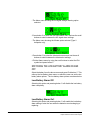
THE ALARM OPTIONS MENU
This is the Alarm menu for determining whether the low battery and/or
low signal strength warnings should sound in the headphone.
You reached this menu by selecting the Alarm option on the main
programming menu.
To return to the main programming menu, select Exit (the Up arrow on
the display) and press pushbutton C.
• The Alarm menu showing the low battery warning option selected.
• Press button C to select the low battery alarm menu and use the
scroll buttons to switch between the low battery alarm settings.
2-8
Clear-Com Communication Systems
Eclipse Wireless Communication System
• The Alarm menu showing the low signal strength warning option
selected.
• Press button C to select the low signal alarm menu and use the scroll
buttons to switch between the low signal alarm settings.
• The Alarm menu showing the Vibrate option selected (Type II
beltpacks only).
• Press button C to select the vibrate alert menu and use the scroll
buttons to switch between the vibrate alert settings.
• Exit the Alarms menu by using the scroll buttons to select the Exit
symbol and press button C.
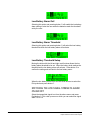
SWITCHING THE LOW BATTERY ALARM ON AND
OFF
Select the battery from the above menu and press Pushbutton C. This
calls up the low battery alarm menu on which the user can set the low
battery alarm options. The low battery alarm options are shown below.
Low Battery Alarm Off
Selecting this option and pressing button C will disable the low battery
alarm completely.
Low Battery Alarm On1
Selecting this option and pressing button C will enable the low battery
alarm setting to alert the user when the batteries need recharging or
replacing.
2-9
Clear-Com Communication Systems
Eclipse Wireless Communication System
Low Battery Alarm On2
Selecting this option and pressing button C will enable the low battery
alarm setting to alert the user when the batteries reach the threshold
set by the user.
Low Battery Alarm Threshold
Selecting this option and pressing button C will select the low battery
threshold at which the low battery alarm will activate.
Low Battery Threshold Setup
Moving the slider with the left and right scroll buttons allows the low
battery alarm threshold to be set. When the battery level reaches the
threshold set the low battery alarm will activate. Press button C to
confirm the setting and exit back to the low battery menu.
When the low battery alarm is set use the scroll buttons to select the
Exit symbol and press button C.
SWITCHING THE LOW SIGNAL STRENGTH ALARM
ON AND OFF
Select the transmitted signal icon from the above menu and press
Pushbutton C. This calls up menu on which you can select low signal
alarm On or Off.
2-10
Clear-Com Communication Systems
Eclipse Wireless Communication System
.
When the low signal alarm is set use the scroll buttons to select the
Exit symbol and press button C.
THE VIBRABEEP CALL ALERT MENU
This is the menu for determining whether the low battery and/or low
signal strength warnings should use the vibrate function (type II
beltpacks only) and/or an audio beep function.
This menu is reached by selecting the Alarm option on the main
programming menu then selecting the Vibrate/audio option. The alert
options are vibrate only, audio beep only, or vibrate and audio beep
selected by pressing button C to step through the options.
When the required option is selected use the scroll buttons to select
another menu item.
To return to the main programming menu, select Exit (the Up arrow on
the display) and press pushbutton C.
2-11
Clear-Com Communication Systems
Eclipse Wireless Communication System
THE MICROPHONE MENU
From the main programming menu select Settings and then
Microphone Options to display the Microphones menu.
• The Microphones menu will be displayed.
• Select Microphone Type using the scroll buttons to display the
Microphone Type menu.
• Use the scroll buttons to select the microphone type from those
available (Dynamic (Bal) mic, Dynamic (UnBal) mic, Electret mic)
and then press button C to set the microphone type. Use the scroll
button to select the Exit symbol and press button C to return to the
main Microphone menu
• The Microphone menu showing the microphone level option selected.
• This facility allows the user to select a level of microphone gain and
so control the sensitivity of the microphone in the headset. Use the
left and right scroll buttons to set the microphone level by moving
the slider. The level can be set from 20dB to 65dB in steps of 5dB.
• Press button C to select the level setting and return to the previous
menu or use the scroll buttons to select Exit and press button C to
exit.
• The Microphone menu showing the Noisegate level option selected.
2-12
Clear-Com Communication Systems
Eclipse Wireless Communication System
• This facility allows the user to select a level at which the audio is
gated to prevent background noise being transmitted. Use the left
and right scroll buttons to set the microphone level by moving the
slider. The level can be set from 0 (off) to 14 is steps of 1.
• Press button C to select the level setting and return to the previous
menu or use the scroll buttons to select Exit and press button C to
exit.
Release 5.1 includes a mic profile which cuts the bass by 12 dB and
boosts the treble by + 3 dB. This is permanently set for all modes.
The MkII beltpacks include a hardware mic gate and in release 5.1 this
has been activated on Mic noise gate level 1 to allow a very low
whisper on the beltpacks.
SET FACTORY DEFAULTS
To reset the beltpack to the factory defaults go to the main
programming menu and select Set Factory Defaults.
The factory defaults options are NO to cancel the operation or YES to
default all the user settable parameters such as limiters and levels to
the factory settings.
Select NO to cancel or use the scroll buttons to select YES to reset.
.
2-13
Clear-Com Communication Systems
Eclipse Wireless Communication System
When the beltpack is reset to factory defaults and confirmation
message is displayed.
Press any key to return to the main menu.
BUTTON OPTIONS MENU
• Select Button options on the programming menu.
KEYLOCK
Keylock allows the scroll buttons to be disabled when on the main
pageafter 3 seconds of inactivity to prevent accidental activation.
• Select keylock on the button options menu and use the scroll buttons
to select Keylock On or Keylock Off.
• Press button C to set the keylock mode. If keylock is on a symbol will
be displayed on the main pages showing that the keys are locked.
• To temporarily disengage keylock press and hold the scroll keys
simultaneously for 3 seconds. A short beep in the headphones will
signal that the keylock has been disengaged.
2-14
Clear-Com Communication Systems
Eclipse Wireless Communication System
TAP LATCH
The Tap Latch function determines whether the rotary push buttons
latch with one tap or two taps when the beltpack is set in latching
mode.
• Select the Button Options menu from the Programming menu.
• Select the Tap Latch on the Button options menu and use the scroll
keys to toggle between the 1 Tap Latch and 2 Tap Latch states.
• Press button C to set the Tap Latch mode.
PTT CONFIGURATION
PTT configuration allows a PTT switch to be enabled or disabled.
Note: The PTT configuration feature is only available on PD2202
beltpacks.
• To configure PTT set to the Button options menu and use the scroll
keys to select PTT configuration.
• The PTT configuration menu will be displayed. Use the scroll buttons
to enable or disabled the PTT switch.
Clear-Com Communication Systems
Eclipse Wireless Communication System
2-15
Use button C to set the PTT switch status.
THE STATUS (INFORMATION) MENU
This function appears after you have selected the Information symbol
from the the main programming menu.
• The Status (Information) menu showing the Role Information icon
selected. Note that this face icon is used in two different menus. It
appears in the Talk/Listen menu to denote the Talk and Listen
mode and it is used here, in the Status submenu to denote Role
Information.
When this icon is selected the display appears showing the Role
name and the Role number which represents it.
• The Status (Information) menu showing the Beltpack version number
icon highlighted.
• When this icon is selected the display appears.
• The Status (Information) menu showing the Beltpack ID icon
highlighted.
2-16
Clear-Com Communication Systems
Eclipse Wireless Communication System
When this icon is selected the display appears. IPEI stands for
International Portable Equipment Identifier, EMC for Equipment
Manufacturer Code, PSN for Portable Serial Number (unique to
every Beltpack) and C for check-digit.
• The Status (Information) menu showing the Beltpack RF Carrier icon
highlighted.
When this icon is selected the display appears showing the RF
carrier mask in hexadecimal format. This mask is unique to your
country's allowed DECT band. It is set to a default European
mask. See the Product manual for changing this.
• The Status (Information) menu showing the Connection Information
icon highlighted.
When this icon is selected the display appears. The components
of this display are laid out in the format which is specified for this
technology and appear as follows:
Clear-Com Communication Systems
Eclipse Wireless Communication System
2-17
Figure 2-3: Connection Information Display
Table 2-1: Connection Information
Item
Description
1
Radio Fixed Part Identifier. This title refers to the whole of
the second line of text. The RFP is the Radio Fixed Part to
which the Beltpack is currently connected. (Much of this line
of text is not unique to one Active Antenna.)
2
This is the PARK (Primary Access Rights Key) number
(reserved for future use.)
3
The abbreviation stands for Equipment Installer Code and
the number on the second line is the EIC number.
4
Fixed Part Number. This and item 6 below are unique to the
particular Active Antenna.
5
Fixed Part Sub-Number. This is effectively the system
number which identifies which matrix the Beltpack is
registered with.
6
Radio Fixed Part Number. This is the identifier of the Active
Antenna on the system.
7
Carrier Number (both Active Antenna and Beltpack)
8
Timeslot Number (used by Active Antenna)
9
Received Signal Strength Indication (digital indication). This
is an arbitrary number in the range 0-52 and, therefore,
significant only in the context of a particular installation.
10
Block error rate for received frames.
From these displays, press button C to return to the status menu.
2-18
Clear-Com Communication Systems
Eclipse Wireless Communication System
PAGE OPTIONS
The Page Options on the main menu give access to the page lock and
key options menus.
PAGE LOCKING
When you are looking at a normal display you are looking at one of up
to six numbered pages with three key assignments on each. Eclipse
supports up to eighteen key assignments. The page icon indicates the
page number of the current page. The setting of page number is global
to the system and only one page can be current at a time.
The significance of upper and lower case text on the display is
explained in the Operational Information.
To display a different page, change to menu mode and select Page
Options. This will display the page options menu.
Use button C to change the page status from page change allowed to
page locked to prevent the page being changed.
Clear-Com Communication Systems
Eclipse Wireless Communication System
2-19
2-20
Clear-Com Communication Systems
Eclipse Wireless Communication System
3
OPERATING THE
ECLIPSE
TRANSCEIVER/
ANTENNA
TRANSCEIVER/ANTENNA
The Eclipse transceiver/antennas form the transmission link between
the Eclipse beltpacks and the Eclipse base. Multiple units are used to
support the beltpacks and to create larger, customized coverage
areas. Each transceiver/antenna is connected to the Eclipse base,
either directly or via a splitter. The unit has two flanges on the rear side
that permit the unit to be screwed or otherwise attached to surfaces.
Figure 3-1: Eclipse Transceiver/Antenna
TRANSCEIVER/ANTENNA TOP PANEL
Omnidirectional Antennas
A pair of omnidirectional antennas are provided with the
transceiver/antenna.
Clear-Com Communication Systems
Eclipse Wireless Communication System
3-1
Antennas with different coverage patterns (directional units) that are
appropriate for the 1.9 GHz range may be substituted for the provided
antennas, if variations in coverage pattern are required.
TRANSCEIVER ANTENNA BOTTOM/CONTROL
PANEL
Figure 3-2: Eclipse Transceiver/Antenna Bottom/Control Panel
1 Serial Data Connector
This 3 mm (1/8 inch) tip-ring-sleeve (TRS) connector is used for
upgrading the firmware in the transceiver/antenna. It will typically be
unused.
2 Data Signal LED
This yellow LED indicates that a connection has been established
between the Eclipse base and the transceiver/antenna, and that it is
actively creating a coverage zone within which the beltpacks can
operate. If it is off, check the cable connections at both ends, as well as
the powering.
3 Matrix Connector
This RJ-45 connector is used to connect the bi-directional signal from
the Eclipse base, directly or via the splitter. Up to 1,000 meters of
4-pair 24 AWG CAT-5 cable can be used for this connection between
base and transceiver/antenna. If 26 AWG CAT5 cable is used the
maximum distance is 500 meters.
3-2
Clear-Com Communication Systems
Eclipse Wireless Communication System
4 Power LED
This green LED indicates that the transceiver/antenna is receiving
power, either from its local power supply or from the connected CAT-5
cable (distances up to 300 meters, or 925 feet, from the base or the
splitter) being powered via the Eclipse base.
5 DC In Power Connector
This connector is used to locally power the transceiver/antenna with
the supplied universal power supply. Use of local power is required
when the transceiver/antenna is located more than 300 meters (925
feet) from the Eclipse base or the splitter, and is recommended even
when the transceiver/antenna is closer whenever it is available and
convenient.
CABLING THE TRANSCEIVER/ANTENNAS
Each Eclipse transceiver/antenna receives its necessary data and
digital communications audio via a direct connection with the matrix
E-Que ports. Between these two ports, up to 10 transceiver/antennas
can be supported. A transceiver/antenna may either be directly
connected to an E-Que port using 4-pair CAT-5 data cable with RJ-45
connectors on each end, or it may be connected to the base through
an antenna splitter.
BELTPACK SUPPORT CAPACITIES FOR TRANSCEIVER/ANTENNAS
Each transceiver/antenna can support five beltpacks within one
coverage zone. With the supplied omnidirectional antennas, the
coverage pattern is circular or donut-shaped, with a maximum range of
up to 250 meters (800 feet), but with typical range between 50 meters
and 150 meters – depending on the environment in which it is installed.
When designing the system, determine how many beltpack users will
be in or passing through a given coverage zone. If it will be five or
fewer users, then place one transceiver/antenna in the center of that
area. If it is between 6 and 10 users, place two transceiver/antennas
next to each other, both with a direct connection to the Eclipse base or
splitter. In larger systems – approaching 20 beltpacks – it is wiser to
allow one transceiver/antenna for every 3 to 4 users to ensure smooth
handoffs between transceiver/antennas. It is good practice to have
each beltpack “seeing” two or more antennas, so a minimum of two
antennas in any system is to be considered.
If a sixth beltpack user goes into a coverage zone with only one
transceiver/antenna, and that user is out of range from another
transceiver/antenna in the overall system to which that beltpack is
currently connected, it will lose connection with the system. This is
Clear-Com Communication Systems
Eclipse Wireless Communication System
3-3
because the tranceiver/antenna has a maximum capacity of five
beltpacks at a time. If one of the existing users in that coverage area
turns off a beltpack or leaves the area, then the sixth beltpack will find
an open slot and will be reconnected with the system.
The proprietary technology within Eclipse permits the beltpack user to
go between coverage zones created by different transceiver/antennas
connected to the Eclipse base, and for the system to hand over the
communication between beltpack and base from one
transceiver/antenna to the next one. Thus, a larger, customizable
communications area may be designed.
COVERAGE AREAS UNDER VARIOUS CONDITIONS
Just as with any other product communicating via radio waves, the
effective distance between the beltpack and the transceiver/antenna
(the range) will differ depending on the particular environment in which
it is being used. Radio waves can be attenuated by walls, floors,
ceilings, trees, shrubbery, the human body (such as an audience), and
numerous other objects. They can be reflected and/or stopped by
metallic objects such as structural beams, safety doors, lighting
equipment and truss, bodies of water, and so on.
Under ideal conditions, the maximum range between a Eclipse
beltpack and a transceiver/antenna is 250 meters (about 800 feet).
Typical distances are between approximately 50 meters (about 160
feet) and 150 meters (about 485 feet), depending on the particular
environment.
As the transceiver/antenna requirements for a particular installation
are being determined, keep in mind both the number of beltpack users
who will be working in a particular area (based on the five-beltpack
capacity of each transceiver/antenna), and the layout and potential RF
attenuating and reflecting items in the location. Be conservative in your
distance estimates to make sure that you include enough
transceiver/antennas to provide the necessary coverage for the
installation. Also note that additional transceiver/antennas may be
added to a base, up to a maximum of 10.
TRANSCEIVER/ANTENNA SETUP RULES AND TIPS
Keep the following general rules and tips in mind:
• Keep antennas high (typically, though lower placements away
from interfering objects can at times be beneficial) and
line-of-sight.
• Keep them away from larger metallic objects and surfaces, and
from lighting truss.
• With the provided omnidirectional antennas, the coverage is
circular so put the transceiver/antennas in the center of the area
in which you want coverage.
3-4
Clear-Com Communication Systems
Eclipse Wireless Communication System
• In outdoor settings with line-of-sight, the absence of beneficial
reflections of the radio waves may lead to shorter than expected
range; directional antennas may be of benefit here.
• When overlapping the coverage zones of transceiver/antennas to
create larger continuous coverage areas, test the in-between
areas with a beltpack for potential areas of low RF signal; adjust
the positioning of the antennas as needed.
• Because of potential body shielding as the user moves, it will be
useful to place two transceiver/antennas in different locations
within larger working areas to minimize low-level signals and
potential signal dropouts.
• Going between a larger area and a corridor via a door, especially
a heavy or shielded one, or where the walls are thick, place a
second antenna in the corridor near the doorway to assure
continuous coverage.
TRANSCEIVER/ANTENNA SPLITTER
The antenna splitter is the device that connects multiple
transceiver/antennas to the Eclipse matrix. It has an RJ-45 connector
that carries the data between a base transceiver port and the splitter,
and five RJ-45 connectors to feed that information to and from up to
five antennas. The splitter is always locally powered via the supplied
external in-line universal power supply.
SPLITTER FRONT CONNECTOR PANEL
Figure 3-3: Eclipse Splitter Front Connector Panel
1 Base Connection Indicator Light
This yellow light indicates that the splitter is receiving data from the
Eclipse base.
Clear-Com Communication Systems
Eclipse Wireless Communication System
3-5
2 Matrix (Eclipse Base) Connector
This RJ-45 connector accepts a 4-pair data cable from the Eclipse
matrix E-Que port. This cable can be up to 1,000 meters in length if 24
AWG cable is used or up to 500 meters if 26 AWG cable is used.
3 Splitter-to-Transceiver/Antenna Signal Indica-
tor Light
These yellow lights indicate that a connection from the Eclipse base is
available to the particular transceiver connected to that port.
4 Transceiver/Antenna Connectors
These five RJ-45 connectors are used to connect up to five remote
transceiver/antennas to the splitter, and via the splitter to the Eclipse
matrix. Each of these cables can be up to 1,000 meters in length if 24
AWG cable is used or up to 500 meters long if 26 AWG cable is used.
SPLITTER REAR PANEL
1 Serial Data Connector
This 3.5 mm (1/8 inch) tip-ring-sleeve (TRS) connector is used for
upgrading the firmware in the splitter. It will typically be unused.
2 Power Indicator
This green LED indicates that the splitter is receiving power from the
external power supply.
3-6
Clear-Com Communication Systems
Eclipse Wireless Communication System
3 DC IN Power Connector
This connector is used to locally power the antenna splitter with the
supplied universal power supply. Use of local power is required.
4 EXP IN Connector
This male DB-15 connector is reserved for future use.
5 EXP OUT Connector
This female DB-15 connector is reserved for future use.
CONNECTING AN ANTENNA SPLITTER TO THE
ECLIPSE BASE AND TO TRANSCEIVER/ANTENNAS
After the connections have been made between the splitter and the
transceiver/antennas, make sure that the data LED’s are lit at the
individual ports on the antenna splitter. Also make sure that the both
the green power LED and the yellow data LED are lit on each
transceiver/antenna. If all are properly lit, then the connection has
been successfully made and the coverage zones will be active and will
support beltpacks. If the transceiver antennas are not lit, check the
connections.
Clear-Com Communication Systems
Eclipse Wireless Communication System
3-7
3-8
Clear-Com Communication Systems
Eclipse Wireless Communication System
4
INSTALLING A
SYSTEM
You can begin using a Eclipse system as soon as you receive it, as
long as the beltpacks are registered to the base, using the generic user
labels for the beltpacks and the rear-panel connections.
PLACING THE MATRIX
The first stage in setup is placing the matrix in a convenient location,
knowing that it is the central routing unit of the Eclipse system.
An Eclipse wireless system
can work immediately when
you receive it, as long as the
beltpacks are registered to
the system.
At this stage, if they are unregistered, you may want to register all of
the beltpacks with the Eclipse Configuration System (ECS), or at least
register one or two for system setup and testing. Follow the
instructions in the Eclipse Configuration System instruction manual to
register the beltpacks.
PLACING THE ANTENNAS AND SPLITTERS
The next step is to begin placing antennas and splitters to provide the
necessary coverage areas for all of the beltpacks. Your first
placements of antennas and splitters will be experimental and
temporary. After placing the antennas, you will walk through the
coverage areas to check for gaps and then re-locate the antennas
accordingly.
More information on checking coverage areas is given later in this
chapter, in the sections “Determining Coverage Areas” and “Doing a
Site Survey to Determine Coverage Areas.”
The following questions will help you to begin placing the antennas:
• What areas will have more than five active beltpack users in them
at any time? Co-locate a second transceiver/antenna there.
• Is there a central place to locate an antenna so that it will provide
omnidirectional (all directions / circular) coverage?
• Are there balcony areas, corridors, or other rooms or areas that
will require coverage with antennas?
Next decide where the antenna splitter(s) that feed these antennas will
be safely located. For systems with only one or two
transceiver/antennas, the cable runs will go directly from the
transceiver ports on the base E-Que card.
Clear-Com Communication Systems
Eclipse Wireless Communication System
4-1
WIRING THE ANTENNAS AND SPLITTERS
To wire antennas and splitters:
1. Run 4-pair CAT-5 cable from the Eclipse base to the antenna or
splitter, and determine that the antenna or splitter is showing both
power (green LED lit) and signal (yellow LED lit when the matrix is
on).
Note: To meet FCC emissions requirements, you must fit a ferrite
on any CAT-5 cable plugged into either of the two ports
labeled “tranceivers.” The ferrite should be fitted at the
E-Que card end of the CAT-5 cable. Position the ferrite as
close to the E-Que card as possible.
The manufacturer of the ferrite is Wurth Elektronix. The part
number is 742 711 32.
2. Run 4-pair CAT-5 cable from the splitter to each of the
transceiver/antennas.
3. Make sure that the local power supplies are plugged into the
antennas, unless they are close enough to the matrix to draw power
from the attached CAT-5 cable.
You will know that a transceiver/antenna has sufficient power from the
cable if the green power LED and the yellow data LED light up. If you
have several longer runs and are attempting to power the
transceiver/antennas from the base / splitter connection, check each
one again when the are all connected. The local powering for the
transceiver/antenna is recommended in most cases to provide the
most reliable long-term Eclipse installation.
Note that 4-pair CAT-5 cable with RJ-45 connectors on each end is
specified for connection between the E-Que card and the
transceiver/antennas. Use of other cable can result in markedly shorter
distances of cable runs and other possibly other performance
problems.
During the initial system setup, before walking through the system with
a beltpack to check for gaps in coverage, it is wise to avoid
“permanently” installing the transceiver/antennas. Hold them in place
in some temporary way until their optimal position is determined.
DETERMINING COVERAGE AREAS
After you have initially set up the transceiver/antennas and splitters,
you can proceed to test the coverage areas and re-locate antennas
and splitters, if necessary, for optimal coverage.
To determine coverage areas:
1. Once the base, splitter(s), and transceiver/antennas have been
placed and wired, turn on a beltpack (assuming that it has been
registered with ECS) and walk the coverage area – ideally speaking
4-2
Clear-Com Communication Systems
Eclipse Wireless Communication System
with someone else via the on-base headset or a party-line or matrix
connection with the base.
Alternatively, use the “site survey” mode on the beltpack (see “Doing
a Site Survey to Determine Coverage Areas” below). It is often best
to begin with one antenna in place, and then place additional units to
enhance coverage.
2. Walk through all of the areas where beltpack users will typically be
moving, and note any areas of weak signal, dropout, or
disconnection from the system. Pay special attention to the overlap
areas between antenna coverage zones, making sure sufficient
signal strength is there from each of the transceiver/antennas to
make a clean handoff between them for the beltpack.
3. Finally, when the coverage zones have been properly and effectively
set up, it is time to program the system. See the ECS Instruction
manual for setting up a system.
DOING A SITE SURVEY TO DETERMINE
COVERAGE AREAS
Some Eclipse users may want to test coverage areas more extensively
before setting up a a complete system. Testing a system in the setting
in which it will be located helps you to set up the system successfully to
meet your needs. Factors in the local setting may affect the areas a
system can cover, so it is important to plan a site setup accordingly.
Doing a complete site survey, as described below, helps you to set up
an optimal system.
TESTING COVERAGE AREAS OF INDIVIDUAL
ANTENNAS
1. Place the Eclipse matrix in a convenient location. Register one
beltpack to the matrix.
2. Place one antenna in the center of the coverage area.
3. Put the beltpack into “site survey mode” by first pressing the power
button on the back of the beltpack, and then simultaneously
pressing the two front-panel scroll buttons.
• When you do this, the beltpack’s display shows the “site survey”
screen. Figure 4-1 shows a beltpack’s site survey screen.
4. Walk around the antenna with the beltpack, monitoring the
beltpack’s signal strength and error rate at various distances.
The signal strength is shown in the Received Signal Strength
Indication (RSSI) field in the leftmost lower corner of the beltpack’s
display. The error rate is shown in the ERR field in the middle of the
display.
Clear-Com Communication Systems
Eclipse Wireless Communication System
4-3
Figure 4-1: A Beltpack’s Site Survey Screen
• The RSSI (signal strength) number will fluctuate, ranging from 0 to
55, as you walk through the coverage area, and may even
fluctuate as you stand still. As a rule-of-thumb, you will obtain best
system performance when the signal strength remains at 30 or
above. If the signal strength falls below 30, you may start losing
audio. This is the limit of the coverage zone.
• The ERR (error rate) number indicates packets of audio which are
lost or corrupted. When this number exceeds a few percent you
may start hearing audible audio breakup.
A beltpack can transmit to an antenna outdoors at an average
distance of 125 meters when the beltpack has an unobstructed
“line-of-sight” path to the antenna. In ideal conditions, the range may
be as high as 250 meters. Indoors, a beltpack can transmit to an
antenna at an average distance of 50 meters.
5. Draw a map of the coverage zone for the antenna. The coverage
zone is the area where the signal strength, as a rule-of-thumb, is 30
or above and the error rate is below a few percent.
6. Repeat this process, one antenna at a time, for as many antennas
as necessary to cover the required area. Overlap coverage zones
so that there is no area where the signal strength is below 30, and
no area where the error rate is above a few percent.
7. You will need to adjust antenna placement to get the best coverage.
4-4
Clear-Com Communication Systems
Eclipse Wireless Communication System
Zone A
1 User
Zone B
5 Users
Zone C
4 Users
Figure 4-2: Mapping overlapping coverage zones
In some environments you may observe that despite having a high
signal strength, the beltpack consistently reports a high error rate.
This could be due to two things:
• In-band interference from an RF source broadcasting in the DECT
area of the spectrum. This can be verified using a DECT band
monitor (which can be purchased from Vitec Group
Communications), or by using a Spectrum Analyser.
• Long Delay Spread Multipath, where the signal is bounced off a
number of reflective surfaces, such as metal ceilings, gantries,
walkways or other large structures. This problem is greatest
where the reflective surface is large and exists at a range of
distances from the antenna. To resolve this problem, consider
siting the antenna where it cannot “see” the reflective surface,
installing a reflector close to the antenna between it and the
reflective surface, or purchasing directional antennas. Contact
VGC customer support for more information.
TESTING ANTENNA HANDOFF
After you test the coverage areas for individual antennas, test the
handoff between the antennas. When you walk through a coverage
area with the beltpack, the beltpack searches to find the antenna with
the best signal strength, and switches transmission to that antenna.
Therefore the beltpack continually hands off transmission among
antennas as you move through the coverage area.
To test antenna handoff, connect any additional antennas in the
installation and walk through the coverage areas to ensure that the
coverage is continuous and complete, without audio breakups. You
can tell which antenna the beltpack transmits to by looking at the RPN
number in the top rightmost corner of the beltpack’s display when the
beltpack is in “site survey” mode. Reposition antennas if necessary.
Note that the numbering to identify antennas starts at “6” to identify the
first antenna, as shown in the table below.
Clear-Com Communication Systems
Eclipse Wireless Communication System
4-5
BELTPACK SCREEN DISPLAYS:
RPN 6
RPN 7
RPN 8
RPN 9
RPN 10
RPN 11
RPN 12
RPN 13
RPN 14
RPN 15
WHICH SIGNIFIES:
Antenna 1 on transceiver port 1
Antenna 2 on transceiver port 1
Antenna 3 on transceiver port 1
Antenna 4 on transceiver port 1
Antenna 5 on transceiver port 1
Antenna 1 on transceiver port 2
Antenna 2 on transceiver port 2
Antenna 3 on transceiver port 2
Antenna 4 on transceiver port 2
Antenna 5 on transceiver port 2
Table 4-1: How antennas are numbered
ASSIGNING BELTPACKS TO COVERAGE AREAS
Each antenna is designed to handle five beltpacks simultaneously.
Although it can achieve this in good conditions, this may not always be
possible for a number of reasons. First, interference or propagation
problems may mean that not all antenna slots are available all the
time. Second, a beltpack constantly searches for the best antenna
signal, and may frequently switch antennas. To make this transmission
seamless, a beltpack maintains the connection to its current antenna
until it is confident that the new antenna is functioning well. Therefore,
for a short period of time during this transition, a single beltpack can
occupy slots on more than one antenna.
This means that for zones in which you are likely to need coverage for
five or more beltpacks simultaneously, it is recommended that you
install a second antenna. Similarly, for good coverage for nine or more
beltpacks simultaneously, a third antenna may be required.
CONDITIONS AFFECTING COVERAGE AREAS
The environment in which a system is located affects the coverage
area for any particular beltpack/antenna combination. The presence of
walls, floors, ceilings, trees, shrubbery, people, and numerous other
items may affect the coverage zone. Metallic objects, safety doors,
lighting equipment, and bodies of water may possibly block
transmission. You must take these factors into consideration when
planning your installation.
4-6
Clear-Com Communication Systems
Eclipse Wireless Communication System
5
SPECIFICATIONS
Eclipse Beltpack
Beltpack Frequency Response
100 Hz – 7.1 kHz
Beltpack Assignment-Select Buttons 3, used to scroll and select talk/listen
“pages”
and also to edit beltpack menu options
“Label” Assignments per Select Button2 (two simultaneous talk/listen paths or
channels)
Number of Full-Duplex Audio Paths 6 (3 pairs), with individual level control
Level/Talk Controls
encoders
2 top-mounted push-to-talk rotary
Headset Connector
4-pin male, Clear-Com standard
Headset Impedance
32 ohm to 2000 ohm
Microphone Type
beltpack
Dynamic or electret, selectable in
menu
Microphone and Headset Limiters
Selectable in beltpack menu
Powering
Alkaline Battery, 4 AA alkaline cells
Rechargeable, 4 NiMH cells in AA format
Battery Charging
supply
In unit, via supplied external power
connected to beltpack
Battery Life
Range from Single
Transceiver/Antenna
Approximately 8 hours with 4 fresh AA
alkaline batteries or 4 AA high-amperage
NiMH cells
125 m from transceiver/antenna in
line-of-sight conditions; 50 m indoors;
use
multiple transceiver/antennas for larger,
custom coverage areas
Clear-Com Communication Systems
Eclipse Wireless Communication System
5-1
Dimensions
Tapered design, at largest points approx.
38 x 87 x 144 mm (dwh)
(1.5 x 3.5 x 5.75 inches)
Weight (with batteries)
Approx. 13 oz.
Transceiver/Antenna
Beltpacks Supported Per
Transceiver/Antenna
5, in one cellular zone
Transceiver Antenna Transmission
Range
Up to 250 m (800 ft.), line of sight
Maximum Distance, Base to Transceiver
Via Base Port
1,000 m (3,200 ft.) using 24 AWG cable
500 m (1,600 ft) using 26 AWG cable
Maximum Distance, Transceiver Powered
By Base Port
300 m (975 ft.)
Local Powering
Via 24VDC power supply
Range per Transceiver/Antenna
150 m from transceiver/antenna
ideal, line-of-sight conditions; 50 m
indoors;
use multiple transceiver/antennas for
larger,
custom coverage areas
5-2
Connection to Eclipse Base
RJ-45
Mounting
Via integral tabs with holes for screws
Dimensions
38 x 125 x 153 mm (dwh)
(1.5 x 5.0 x 6.1 inches)
Weight
Approx. 9 oz.
Clear-Com Communication Systems
Eclipse Wireless Communication System
Transceiver/Antenna Splitter
Number of Transceiver/Antennas
Supported
the
10; Note: In the USA, until FCC opens
allowed bandwidth, any one
area
can only have 5 antennas.
Number of Splitters Per Base
2
Connection Between Base
and Splitter
4-pair CAT5 cable with RJ-45
Connection Between Splitter and
Transceiver/Antennas
4-pair CAT5 cable with RJ-45
Powering of Splitter
supply
Locally powered via external power
Transmission Method
Method of RF Operation
per
DECT standard, using two DECT bands
beltpack for wider frequency response
Modulation
QPSK
Frequencies of Operation
1.92 – 1.93 GHz
RF Output
250 mW burst, average level 2 - 4 mW
Theory of Operation
Dynamic allocation of frequencies and handoff of beltpacks among the
transceiver/antennas up to their individual limit of 5 connected beltpacks at a
time; each beltpack is assigned a “virtual port” within the Eclipse base.
Clear-Com Communication Systems
Eclipse Wireless Communication System
5-3
5-4
Clear-Com Communication Systems
Eclipse Wireless Communication System
APPENDIX 1: DECT
CARRIER
FREQUENCY CHART
RFC
carrier frequency
rfc
carrier frequency
0
1897.344
17
1911.168
1
1895.616
18
1912.896
2
1893.888
19
1914.624
3
1892.160
20
1916.352
4
1890.432
21
1918.080
5
1888.704
22
1919.808
6
1886.976
23*
1921.536
7
1885.248
24*
1923.264
8
1883.520
25*
1924.992
9
1881.972
26*
1926.720
10
1899.072
27*
1928.448
11
1900.800
28
1930.176
12
1902.528
29
1931.904
13
1904.256
30
1933.632
14
1905.984
31
15
1907.712
32
16
1909.440
Table 6-1: DECT Carrier Frequency Chart
* Carriers 23 through 27 are those used in the USA.
Clear-Com Communication Systems
Eclipse Wireless Communication System
6-1
6-2
Clear-Com Communication Systems
Eclipse Wireless Communication System
7
GLOSSARY
Analog Port Any of the Eclipse matrix’s analog input/output RJ-45
connectors that are used to connect cable from the matrix to panels
and interfaces. Each “port” connects to a separate audio channel in the
matrix intercom system.
Bus A bus is the channel or path between the components in the
matrix along which electrical signals flow to carry information from one
component to the next. In the Eclipse matrix the bus is located in the
etched surface of the midplane.
Call Signal A call signal is an electronic signal sent from one panel or
interface to another. A call signal can be audible and/or visual.
Typically a call signal is sent to get the attention of a panel operator
who may have turned down their intercom speaker’s volume or
removed their headset. It can also be sent to activate an electronic
relay.
Category-5 cable EIA/TIA 568 category specification relating to
network cabling. Shielded category-5 cabling is required for Eclipse
matrix wiring.
CellCom Digital wireless communications product. Sold under the
CellCom name in USA and as FreeSpeak in Europe and Asia.
Central Matrix The term “central matrix” is used to differentiate the
central hardware and software of the intercom system from the
connected audio devices. The central matrix consists of:
1. The metal housing for the circuit cards and power supplies.
2. The circuit cards.
3. The power supplies.
4. The rear panel connectors which connect the matrix’s hardware to
panels and interfaces.
Destination A device such as an intercom panel, beltpack, or interface
to which audio signals are sent. The device from which audio signals
are sent is called a “source”.
Duplex All real-time communication between individuals talking face to
face is full duplex, meaning that they can both talk and listen
simultaneously. The Eclipse Omega matrix provides full-duplex audio.
ECS Eclipse Configuration System. Software program that guides the
operation of the central matrix circuit cards and connected panels.
EMS Element Management System. Software program that is used to
manage the Concert server system resources.
Ethernet International standard which describes how information is
transmitted across a network. Provides for the efficient organization of
network components.
Clear-Com Communication Systems
Eclipse Glossary
7-1
Fiber-optic Cable A fiber-optic cable consists of a glass core covered
with a reflective material called “cladding” and several layers of buffer
coating to protect the cable from the environment. A laser sends light
pulses through the glass core to the other end of the cable.
FreeSpeak Digital wireless communications product. Sold under the
FreeSpeak name in Europe and Asia and CellCom in USA.
Full Duplex Refers to transmission of signals in two directions
simultaneously.
IFB “Interruptible Foldback”. The term “foldback” refers to sending
“program” audio, or some other audio mix, back to announcers while
they are on the air. Doing so allows announcers to monitor
themselves, other announcers, videotapes of commercials, or some
mix of sources, while they on the air. This is typically found in television
news and live broadcast events.
Announcers typically wear a small ear piece so they can hear the
selected foldback audio mix. When a director wants to give directions
to an announcer on air, or to announce changes in the program, the
director must “interrupt” the foldback. To do this, the director uses a
channel specifically set up to interrupt the foldback audio.
Interface Module A piece of electronic hardware designed to convert
the 4-wire signals of a central matrix port to some other form of
communication, such as 2-wire party line, telephone, etc. The interface
module is connected to a central matrix port. The external non-4-wire
device is then connected to the interface module.
ISO The ISO function, short for “panel ISOlation”, allows a panel
operator to call a destination and interrupt all of that destination’s other
audio paths and establish a private conversation. When the call is
completed the destination’s audio pathways are restored to their
original state before the interruption.
IV-R Instant Voice Router. Software that routes digital audio data
between Concert users and between Concert users and Eclipse
systems.
Label A label is an alphanumeric name of up to five characters that
identifies a source, destination, or control function accessed by an
intercom panel. Labels appear in the displays of the intercom panel.
Labels can identify panels, ports interfaced to other external
equipment, fixed groups, party lines, and special control functions.
Mode A term used to describe a light path through a fiber as in
multimode or single mode.
Multimode Fiber-optic Cable The glass core of a multimode fiber is
larger than the core of a single mode fiber, which causes the
transmitted light beam to disperse as it travels through the core. Single
mode fiber, with its smaller core, concentrates the light beam so that it
carries signals further. Multimode fiber was the first type of fiber offered
7-2
Clear-Com Communication Systems
Eclipse Glossary
by manufacturers. Single-mode fiber evolved as production methods
improved.
Multiplexing The process by which two or more signals are
transmitted over a single communications channel. Examples include
time division and wavelength division multiplexing.
Nanometer (nm) Common unit of measure for wavelength. One
billionth of a meter.
Non-volatile Memory Data stored in the CPU’s firmware (ROM) that
is not lost when the power is turned off.
Optical Signal A laser at one end of a fiber-optic cable pulses on or off
to send a light signal through the glass core of the cable to the other
end of the cable. Because the light signals are binary (on or off), the
signal is digital.
Panel Also referred to as “station” in some cases (usually older
manuals). Any intelligent intercom device connected to the rear-panel
analog ports of the central matrix. This term does not refer to devices
connected through interface modules.
Port Any of the input/output connections (RJ-45 connectors) on the
back panel of the central matrix. These connectors and the attached
cables connect the central matrix to remote intercom devices. The
term “port” emphasizes that the connection is a “portal” between the
central matrix and the remote intercom devices.
Program Any separate audio source that is fed into the intercom
channels. In television applications, for example, “program” audio is
the audio that is broadcast on air.
Rack Unit or RU Standardized unit of mounting space on a rack panel.
Each rack unit is 1.75 inches (44.45 mm) of vertical mounting space.
Therefore 1 RU is 1.75 inches (44.45 mm) of vertical mounting space,
2 RU is 3.5 inches (88.9 mm), 3 RU is 5.25 inches (133.35 mm), and
so on.
Remote Panel Any intelligent intercom device connected to the
back-panel ports of the central matrix. This term does not refer to
devices connected through interfaces.
Sidetone The sound of the panel operator’s own voice heard in their
own earphone as they speak.
Single-mode Fiber-optic Cable The glass core of a single-mode fiber
is smaller in diameter than the core of a multimode fiber, so that the
light signal transmitted over the core is more concentrated than with
multimode fiber, which allows the signal to travel further. Single-mode
fiber evolved from multimode fiber as production methods improved.
Source In this manual, the term “source” refers to a device—such as
an intercom panel, interface, or beltpack —that sends audio into the
matrix. The device to which audio is sent is called a “destination”.
Clear-Com Communication Systems
Eclipse Glossary
7-3
VOX In the Eclipse system, when audio at a panel exceeds a
threshold, a light switches on at the panel’s port card to visually cue the
operator. The threshold level is set in the Eclipse Configuration
Software.
V-Series Communications panels used with Eclipse systems providing
advanced facilities. Available in rack mount and desktop formats.
Wavelength-division Multiplexing (WDM) A method of multiplexing
optical signals developed for use on fiber-optic cable. Each signal is
assigned a particular wavelength on the light spectrum and therefore
many signals can be transmitted simultaneously without interfering
with each other.
7-4
Clear-Com Communication Systems
Eclipse Glossary
ECLIPSE MANUALS
The following manuals are available covering Eclipse products and
accessories.
SOFTWARE MANUALS
Eclipse Configuration System (ECS) Instruction Manual - 810299Z
Eclipse Logic Maestro Instruction Manual - 810414Z
Eclipse Production Maestro Quick Start Guide - 810409Z
Eclipse Production Maestro Installation and User Guide - 810410Z
Eclipse DECTSync Manual - 810412Z
Eclipse Host Computer Interface (HCI) Manual - 810413Z
HARDWARE MANUALS
Eclipse Omega Matrix Instruction Manual - 810290Z
Eclipse Median Matrix Instruction Manual - 810347Z
Eclipse PiCo Matrix Instruction Manual - 810348Z
Eclipse-32 Matrix Instruction Manual - 810315Z
Eclipse Matrix Installation Manual - 810298Z
Eclipse Upgrade Reference Manual - 810377Z
Eclipse V-Series Panels User Manual - 810365Z
Eclipse FOR-22 4-Wire Interface Instruction Manual - 810306Z
Eclipse CCI-22 Party Line Interface Instruction Manual - 810307Z
Eclipse TEL-14 Telephone Interface Instruction Manual - 810308Z
Eclipse GPI-6 General Purpose Inputs Instruction Manual - 810309Z
Eclipse RLY-6 General Purpose Outputs Instruction Manual - 810310Z
DIG-2 Digital Interface Instruction Manual - 810311Z
IMF-3, IMF-102, DIF-102 Interface Module Frame Instruction Manual 810313Z
Eclipse AES-6 Digital Interface Instruction Manual - 810383Z
Eclipse BAL-8 Isolation Interface Instruction Manual - 810403Z
Eclipse V-Series AES-3 Option Card Installation Instructions 810388Z
Eclipse V-Series XLR-7M Upgrade Instructions - 810405Z
Eclipse V-Series T-Adapter Installation Instructions - 810406Z
Eclipse FIM-202D Fiber Interface Instruction Manual - 810385Z
Clear-Com Communication Systems
Eclipse Manuals
7-5
Eclipse FIM-102 Fiber Interface Instruction Manual - 810319Z
Eclipse FIM-108 Fiber Interface Instruction Manual - 810291Z
Eclipse 4000 Series II Panels Installation Guide - STA0530Z
Eclipse 4000 Series II Panels User Guide - STA0531Z
Eclipse ICS 1008E/1016E Panels Instruction Manual - 810404Z
Eclipse ICS 102/62 Panels Instruction Manual - 810302Z
Eclipse ICS 2003 Panel Instruction Manual 810303Z
Eclipse ICS 92/52 Panels Instruction Manual - 810301Z
Eclipse i-Station Instruction Manual - 810305Z
Eclipse ICS-21 Speaker Panel Instruction Manual - 810263Z
Eclipse ICS-22 Speaker Panel Instruction Manual - 810264Z
Eclipse ICS-24 Headset Panel Instruction Manual - 810265Z
Eclipse Digital Wireless Beltpack Instruction Manual - 810376Z
7-6
Clear-Com Communication Systems
Eclipse Manuals
LIMITED WARRANTY
This document details the Clear-Com Standard Limited Warranty for all new products for sale within all
regions with the exception of Military, Aerospace, and Government (MAG).
EXCEPT AS SET FORTH HEREIN ("LIMITED WARRANTY"), CLEAR-COM MAKES NO OTHER
WARRANTIES, EXPRESS, IMPLIED OR STATUTORY, INCLUDING WITHOUT LIMITATION ANY
WARRANTIES OF MERCHANTABILITY, NONINFRINGEMENT OF THIRD PARTY RIGHTS, OR
FITNESS FOR A PARTICULAR PURPOSE, ALL OF WHICH ARE EXPRESSLY DISCLAIMED.
1. Standard Limited Warranty. Clear-Com Communication Systems ("Clear-Com") warrants its
products, including supplied accessories, against defects in material or workmanship for the time
periods as set forth below provided it was purchased from an authorized Clear-Com dealer or
distributor.
a) Pursuant to this Limited Warranty, Clear-Com will, at its option:
i)
repair the product using new or refurbished parts, or;
ii) replace the product with a new or refurbished product.
b) Remedies: In the event of a defect, the rights detailed in 1 (a) are your exclusive remedies. For
purposes of this Limited Warranty, "refurbished" means a product or part that has been returned
to its original specifications.
c) Standard Warranty Period (by Product):
i)
All Clear-Com brand systems and products, including belt packs, have a Limited Warranty
of two years, with the exception of;
(1) Cables, accessories, components & consumable items have a Limited Warranty of 90
days.
(2) Any Clear-Com product that has been classified as obsolete at the time of sale has a
Limited Warranty of 90 days from sales and will be replaced with the same product or a
sales credit will be issued, at the sole discretion of Clear-Com.
(3) Headsets, handsets, microphones, and associated spare parts, as well as UHF wireless
IFB products, have a Limited Warranty of one year.
(4) UHF WBS Analog wireless intercom systems have a Limited Warranty of three years.
Clear-Com Communication Systems
Standard Limited Warranty
i
(5) All software products, including Concert (Client and Server), ECS, Production Maestro
and Logic Maestro are warranted for one year and shall substantially conform to
published specifications. The media on which the Software is furnished is warranted to
be free of defects in material and workmanship (under normal use) for a period of one
year.
(6) Any Clear-Com products that are listed within the last time buy period have the same
Limited Warranty for their type 1.i 1 - 1.i.5 as above.
d) Any Clear-Com product that is repaired or supplied as a replacement under the terms of this
Limited Warranty shall inherit the remaining warranty period from the original product.
e) Standard Warranty Period Start Date
i)
Dealer / Distributor Sales: In view of Dealer or Distributor stocking practices, the Standard
Warranty Period for products sold through Dealers or Distributors will commence from the
Clear-Com invoice date and will include an automatic extension of three months. Any valid
warranty claim within the Standard Warranty Period as determined by the Clear-Com
invoice date will be covered without further supporting evidence. All warranty claims after
this date must be supported by the Customer's proof of purchase that demonstrates the
product is still within the Standard Warranty Period (as detailed in Section 1.c.i above, plus
the automatic three month extension) from their purchase date.
ii) Direct Sales: The Standard Warranty Period will commence from the date the product was
shipped from Clear-Com to the Customer. The Standard Warranty Period start date for
contracts that include commissioning will be the date of the Site Acceptance Test (SAT) or
one month from conclusion of the commissioning project, whichever is earlier.
f) Invalidation of Warranty
i)
This Limited Warranty shall be invalidated if the product's outer case has been opened and
internal modifications have been made or damage has occurred, or upon the occurrence of
other damage or failure not attributable to normal wear and tear. Authorized modifications
with Clear-Com's express written permission will not invalidate the warranty.
g) Software Updates
i)
ii
Software Updates are released periodically to correct discovered program bugs. During the
Warranty Period, software updates are available to Customers free of charge.
Clear-Com Communication Systems
Standard Limited Warranty
h) Software Upgrades
i)
Software Upgrades include new Features and/or Functional Enhancements and are not
included as part of the Standard Warranty but may be purchased at the published rates.
ii) Note: In the absence of a Software Update containing a program correction and no
available workaround to mitigate the problem, at the discretion of Service, Sales,
Engineering, or Product Management, the Customer may be provided a Software Upgrade
under warranty.
2. Exclusions. Services do not cover damage or failure caused by any occurrence beyond Clear-Com's
reasonable control, including without limitation acts of God, fire, flooding, earthquake, lightning, failure
of electric power or air conditioning, neglect, misuse, improper operation, war, government
regulations, supply shortages, riots, sabotage, terrorism, unauthorized modifications or repair, strikes,
labor disputes or any product failure that Clear-Com determines is not a result of failure in the
Services provided by Clear-Com. Further Services excluded from this Agreement include: services
required due to errors or omissions in Customer purchase orders; installation or maintenance of
wiring, circuits, electrical conduits or devices external to the products; replacement or reconditioning
of products which, in Clear-Com's opinion cannot be reliably maintained or properly serviced due to
excessive wear or deterioration; Customer's failure to maintain the installation site in accordance with
the environmental specifications of the products; or service on products removed from the location
originally specified by Customer and/or reinstalled without the prior written approval of Clear-Com.
Customer will pay Clear-Com's then current published charges to restore such Covered Products to a
condition eligible for further service under this Agreement. Clear-Com shall be excused from and shall
not be liable for any failure or delay in performance under this Agreement due to the foregoing or any
causes beyond its reasonable control.
3. Limitation of Liability. IN NO EVENT WILL CLEAR-COM BE LIABLE UNDER THIS AGREEMENT
FOR ANY INDIRECT, SPECIAL, INCIDENTAL OR CONSEQUENTIAL DAMAGES (INCLUDING
WITHOUT LIMITATION LOST PROFITS), REGARDLESS OF THE FORM OF ACTION, EVEN IF
ADVISED IN ADVANCE OF THE POSSIBILITY OF SUCH DAMAGES.
4. Assignment. Neither party may assign this Agreement or any portion thereof without the prior written
consent of the other, except in the event of a merger, sale of all or substantially all of the assets or
other corporate reorganization.
5. Ownership of replaced parts or product. All replaced parts or products become the property of
Clear-Com.
6. Entire Agreement. This Agreement constitutes the entire agreement between the parties with
respect to the subject matter hereof, and supersedes all prior or contemporaneous proposals, oral or
written, and all other communications between them relating to the subject matter of this Agreement.
Clear-Com Communication Systems
Standard Limited Warranty
iii
iv
Clear-Com Communication Systems
Standard Limited Warranty
TECHNICAL SUPPORT & REPAIR POLICY
NOVEMBER 1, 2008
In order to ensure that your experience with Clear-Com and our World Class products is as beneficial,
effective and efficient as possible, we would like to define the policies and share some "best practices"
that can accelerate any problem solving processes which we may find necessary and to enhance your
customer service experience. Our Technical Support, Return Material Authorization, and Repair Policies
are set forth below. These Policies are subject to revision and constantly evolve in order to address our
Customers' and the Market's needs. Accordingly these are provided by way of guidance and for
information only and may be changed at anytime with or without Notice.
TECHNICAL SUPPORT POLICY
a) Telephone, online, and e-mail technical support will be provided by the Customer Service Center
free of charge during the Warranty Period.
b) Technical support will be provided free of charge for all software products under the following
conditions:
i)
The application, operating, and embedded software is installed on a product covered by
Clear-Com's Limited Warranty, and:
(1) The software is at the current release level; or,
(2) The software is one (1) version removed from current.
ii) Older versions of software will receive "best-effort" support, but will not be updated to
correct reported bugs or add requested functionality.
c) For Technical Support:
i)
North and South America, (inc. Canada, Mexico, and the Caribbean) & US Military:
Hours:
0800 - 1700 Pacific Time
Days:
Monday - Friday
Tel:
+1 510 337 6600
Email:
[email protected]
ii) Europe, the Middle East and Africa:
Hours:
0800 - midnight Central European Time
Clear-Com Communication Systems
Technical Support & Repair Policy
v
Days:
Tel:
Email:
iii) Asia-Pacific:
Hours:
Days:
Tel:
Email:
Monday - Friday
+49 40 853 999 700
[email protected]
0800 - 1700 Pacific Time
Monday - Friday
+1 510 337 6600
[email protected]
d) Email Technical Support is available for all Clear-Com branded products free of charge for the life
of the product, or two years after a product has been classified as obsolete, whichever comes
first.
e) Support for Distributor and Dealer Sales
i)
Distributors and Dealers may utilize the Customer Service Centers once a system has been
installed and commissioned. Clear-Com Systems and Applications Engineers will provide
support to the Distributor from the pre-sales stage through to satisfactory installation for new
system purchases. Customers will be encouraged to contact their Dealer or Distributor with
their installation and technical support enquires rather than using the Customer Service
Centers directly.
f) Support for Direct Sales
i)
Customers may utilize the Customer Service Centers once a system has been installed and
commissioned by Clear-Com Systems and Applications Engineers, or in the case of project
installations, once the Project Team has completed the hand-over to the Support Centers.
RETURN MATERIAL AUTHORIZATION POLICY
a) Authorizations: All products returned to Clear-Com or a Clear-Com Authorized Service Partner
must be identified by a Return Material Authorization (RMA) number.
b) The Customer will be provided with an RMA number upon contacting Clear-Com Sales Support
as instructed below.
c) The RMA number must be obtained from Clear-Com via phone or email prior to returning product
to the Service Center. Product received by the Service Center without a proper RMA number is
subject to return to the Customer at the Customer's expense.
vi
Clear-Com Communication Systems
Technical Support & Repair Policy
d) Damaged equipment will be repaired at the Customer's expense.
e) Returns are subject to a 15% restocking fee.
f) Advance Warranty Replacements (AWRs);
i)
During the first 30 days of the Standard Warranty Period: Once the equipment fault has
been verified by Clear-Com or its authorized representative, Clear-Com will ship a new
replacement product. The Customer will be provided with an RMA number and be required
to return the faulty equipment within 14 days of receipt of the replacement or will be invoiced
for the list price of a new product.
ii) During days 31-90 of the Standard Warranty Period: Once the equipment fault has been
verified by Clear-Com or its authorized representative, Clear-Com will ship a like-new, fully
refurbished replacement product. The Customer will be provided with an RMA number and
be required to return the faulty equipment within 14 days of receipt of the replacement or will
be invoiced for the list price of a new product.
iii) To obtain an RMA number or request an AWR:
(1) North and South America, Asia-Pacific, and US Military:
Hours:
0800 - 1700 Pacific Time
Days:
Monday - Friday
Tel:
+1 510 337 6600
Email:
[email protected]
(2) Europe, the Middle East and Africa:
Hours:
0800 - 1700 GMT + 1
Days:
Monday - Friday
Tel:
+ 44 1223 815000
Email:
[email protected]
iv) Note: AWRs are not available for UHF WBS Analog wireless intercom systems. UHF WBS
Analog wireless intercom systems out-of-box failures must be returned to Alameda for
repair.
v) Note: Out-of-box failures returned after 90 days will be repaired and not replaced unless
approved by Clear-Com Management.
vi) Note: AWRs are not available after 90 days of receipt of product unless an AWR Warranty
Extension is purchased at the time of product purchase.
Clear-Com Communication Systems
Technical Support & Repair Policy
vii
vii) Note: Shipping charges, including duties, taxes, and insurance (optional), to Clear-Com's
factory is the responsibility of the Customer. Shipping AWRs from Clear-Com is at
Clear-Com's expense (normal ground or international economy delivery). Requests for
expedited shipping (E.g. "Next-Day Air") and insurance are the responsibility of the
Customer.
REPAIR POLICY
a) Repair Authorizations: All products sent to Clear-Com or a Clear-Com Authorized Service Partner
for repair must be identified by a Repair Authorization (RA) number (see above).
b) The Customer will be provided with an RA number upon contacting Clear-Com Customer
Services as instructed below.
c) The RA number must be obtained from Clear-Com via phone or email prior to returning product to
the Service Center. Product received by the Service Center without a proper RA number is
subject to return to the Customer at the Customer's expense.
d) Return for Repair
i)
Customers are required to ship equipment at their own cost (including transportation,
packing, transit, insurance, taxes and duties) to Clear-Com's designated location for repair.
(1) Clear-Com will pay for the equipment to be returned to the Customer when it is repaired
under warranty.
(2) Shipping from Clear-Com is normal ground delivery or international economy.
Requests for expedited shipping (E.g. "Next-Day Air") and insurance are the
responsibility of the Customer.
ii) Clear-Com does not provide temporary replacement equipment ("loaner") during the
period the product is at the factory for repair. Customers should consider a potential
prolonged outage during the repair cycle, and if required for continuous operations
purchase minimum spare equipment required or purchase an AWR Warranty Extension.
iii) No individual parts or subassemblies will be provided under warranty, and warranty repairs
will be completed only by Clear-Com or its Authorized Service Partners.
iv) Customers requesting a non-warranty repair will be provided an estimate of the total repair
cost prior to the return of the equipment. In the event that Clear-Com is unable to estimate
viii
Clear-Com Communication Systems
Technical Support & Repair Policy
the cost of repair, the Customer may elect to return the product to the factory for an
estimate. The Customer is responsible for shipping costs both to and from the factory in the
event they choose not to accept the estimate.
v) The Customer must provide either a purchase order for the repair work, or will be required
to make an advance payment (as a debit against the Dealer's line of credit, or credit card)
prior to the repaired product being returned to the Customer.
vi) For requesting a Repair Authorization number:
(1) North and South America, Asia-Pacific, and US Military:
Hours:
0800 - 1700 Pacific Time
Days:
Monday - Friday
Tel:
+1 510 337 6600
Email:
[email protected]
(2) Europe, the Middle East and Africa:
Hours:
0800 - midnight Central European Time
Days:
Monday - Friday
Tel:
+49 40 853 999 700
Email:
[email protected]
vii) Note: Clear-Com's Limited Warranty does not cover normal wear and tear. The Customer
will be charged the full cost of the repair if their equipment has been tampered with by
non-approved personnel, or has been subject to damage through electrical failure, liquid
damage or mishandling. The Customer Service Center will provide the Customer with a
cost estimate for any such repairs prior to undertaking the work.
Clear-Com Communication Systems
Technical Support & Repair Policy
ix