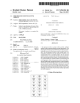
1
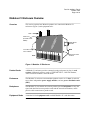
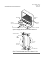
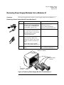
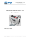
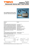
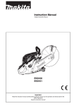
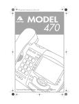
Part No. 09564-2, Rev A
October 1997
Page 1 of 16
MODULUS 21
Power Distribution Unit (PDU) Replacement
Overview
Introduction
This notice explains how to replace the AC Power Distribution Unit (PDU), also
known as a Power Distribution Assembly (PDA), in a Modulus 21 enclosure.
This notice assumes familiarity with Modulus 21-mounted products and the
Modulus 21 itself. Your conÞguration may vary from the examples shown here.
Additional
Information
For details, refer to your device documentation, and to the Modulus 9 and 21
Installation and Operation Guide (Part No. 09564).
In This Manual
Topic
See Page
Modulus 21 Enclosure Overview .................................................................
Removing Product Cards from a Modulus 21 ..............................................
Removing Power Supply Modules from a Modulus 21 ...............................
Removing a Modulus 21 Enclosure From a Rack ........................................
Removing Backplane(s) and the PDU from a Modulus 21 ..........................
Replacing a PDU and Backplane(s) in a Modulus 21 ..................................
Replacing a Modulus 21 in a Rack ...............................................................
Checking Modulus 21 Resistance .................................................................
Re-installing Power Supply Modules in a Modulus 21 ................................
Checking Modulus 21 Voltage ......................................................................
Re-installing Product Cards in a Modulus 21 ...............................................
Returning a PDU to Motorola ISG ...............................................................
PDU Kit Contents
The PDU replacement kit includes:
¥ PDU hardware
¥ PDU replacement label
¥ This document
If your kit is incomplete, contact Motorola ISG Customer Support.
09564-2 A
3
4
6
7
8
10
11
12
13
14
15
16
Part No. 09564-2, Rev A
October 1997
Page 2 of 16
Overview
Modulus 21 Serial
Numbers Affected
This notice refers only to replacing PDUÕs in Modulus 21Õs whose serial number is
one of the following. (For serial-number label location, refer to Figure 5, L.)
¥
¥
¥
¥
¥
¥
¥
¥
¥
¥
¥
¥
¥
¥
¥
¥
¥
3494
5043
285000 - 330000 (range)
549998 - 600000
890000 - 893000
915000 - 999999
2026000 - 9000000
9400000 - 32220000
6009568007
10052388-8
890000A - 999999A
890000B - 999999B
890000D - 999999D
3150000A - 3300000A
3100000B - 3300000B
3100000R - 3300000R
890100DM - 890200DM
Warning!
Only qualified Service personnel should perform this procedure. Use of the
procedure by unqualiÞed personnel could result in personal injury or equipment
damage, which could jeopardize your warranty and maintenance agreement.
Tools Needed
The following tools and supplies are required:
¥
¥
¥
¥
¥
Grounding wrist strap
Labels
Flat- and Phillips- head screwdrivers
Anti-static plastic bags
Multi-meter
Part No. 09564-2, Rev A
October 1997
Page 3 of 16
Modulus 21 Enclosure Overview
Overview
This section explains how Motorola products are contained in Modulus 21
enclosures (Figure 1) and equipment racks.
Rack
Front Door
(Product Cards
Within)
Rack Mount
Bracket
Front Door Hinge
Pin Locations
Front
Back
Front Door Latch
Location
Figure 1. Modulus 21 Enclosure
Product Cards
A Modulus 21 enclosure provides common housing and power for plug-in card
versions of Motorola products, such as 35XX DSU/CSUs, 326X dial modems,
33XX leased-line modems, and 6500 nodes.
Enclosures
The Modulus 21 enclosure accommodates product cards in its 21 slots. It can hold
two or three independent power supply modules, and one power distribution unit
(PDU).
Backplanes
The Modulus 21 can contain one or more product-speciÞc backplanes to carry the
signal and data ßow between product cards and the external environment, and to
provide cable connections to product cards.
Equipment Racks
A standard 19-inch equipment rack can hold Modulus 21Õs and other units.
Part No. 09564-2, Rev A
October 1997
Page 4 of 16
Removing Product Cards from a Modulus 21
Overview
This section explains how to remove product cards from a Modulus 21 enclosure.
Card Removal
Remove product cards and Þller panels from the Modulus 21 enclosure as follows.
IMPORTANT
This procedure removes power from all devices in the Modulus 21. Before you begin,
plan for the effects on your network functions and users.
Warning!
Before you begin, unplug the AC power cord from the power source.
Removing Product Cards from a Modulus 21 Enclosure
Step
Action
Result
1
Attach a grounding wrist strap to
yourself and a grounded object.
Any electrostatic energy is
discharged from you.
2
Unplug both ends of the AC power Power is removed from the
cable (Figure 2, A) from the PDU. Modulus 21 and the devices in it.
3
Open the Modulus 21 front door.
From the front and back of the
Modulus 21, label each product
card and cable connector.
Label each backplaneÕs location.
Card, cable, and backplane
locations and connections are
labelled.
4
Detach the cable connectors from
the backplane(s) (Figure 5, B).
Cables are disconnected.
5
Remove a product card (Figure 3,
A) by pressing its top and bottom
clips apart and pulling it from the
slot. Put the card in an anti-static
bag.
Repeat for each product card.
Cards are removed from Modulus
21. Cards are protected from
damage.
Part No. 09564-2, Rev A
October 1997
Page 5 of 16
Removing Product Cards from a Modulus 21
(PDU Within)
Modulus 21
(Back)
C
Sheetmetal
Retainers
AC Power
Connector on PDU
B
Modulus 21 Sheetmetal
A
AC Power cable is Removed from PDU
Figure 2. Unplugging AC Power Cord from Back of Modulus 21
Unlock
Card top clips
Modulus 21 (Front)
Lock
A
Product
Card
Slide Card
Into Slot
Slide Card
Out of Slot
Unlock
Card Bottom Clips
B
Front Filler Panel
Lock
Figure 3. Removing/Installing Product Cards in Modulus 21 Slots
Part No. 09564-2, Rev A
October 1997
Page 6 of 16
Removing Power Supply Modules from a Modulus 21
Overview
This section explains how to remove a power supply module from a Modulus 21.
Removing a Power Supply Module From a Modulus 21
Step
Action
Result
1
Ensure that you are wearing a
grounding wrist strap and that the
AC power cable is disconnected
from the PDU (Figure 5, A).
Any electrostatic energy is
discharged from you.
Power is removed from the
Modulus 21 and the devices in it.
2
With the Modulus 21 front door
open, squeeze the two front door
hinge pins (Figure 1) toward each
other until the pins are free.
Remove the front door.
Modulus 21 front door is removed.
3
Insert a ßat-blade screwdriver into
each of a power supplyÕs two
locking tabs (Figure 4, A). Gently
turn the screwdriver until the tab
clicks.
Pull the power supply module
(Figure 4, B) from the Modulus 21.
4
Repeat for each power supply
module.
Power supply modules are
removed from the Modulus 21.
Modulus 21 (Front)
B
Power Supply
Modules
A
Locking Tab
Locations
Figure 4. Removing Power Supply Modules From Modulus 21
Part No. 09564-2, Rev A
October 1997
Page 7 of 16
Removing a Modulus 21 Enclosure From a Rack
This section explains how to remove the Modulus 21 enclosure from a rack.
Warning!
The Modulus 21 enclosure is heavy. To avoid injury, two people should remove it.
Removing a Modulus 21 Enclosure from a Rack
Step
Action
Result
1
Ensure that the AC power cable is
disconnected from the PDU
(Figure 5, A).
2
Position one person in front of the
Modulus 21 and one at the back.
3
Hold the Modulus 21 in place in
the rack while removing the rack
mount bracket screws (Figure 1).
4
Carefully slide the Modulus 21 out Modulus 21 is removed from rack.
of the front of the rack.
Power is removed from the
Modulus 21 and the devices in it.
Part No. 09564-2, Rev A
October 1997
Page 8 of 16
Removing Backplane(s) and the PDU from a Modulus 21
This section explains how to remove backplanes and the PDU from a Modulus 21.
Removing Product Backplanes and the PDU From a Modulus 21 Enclosure
Step
Action
Result
Any electrostatic energy is
discharged from you.
Power is removed from the
Modulus 21 and the devices in it.
1
Ensure that you are wearing a
grounding wrist strap and that the
AC power cable is disconnected
from the PDU (Figure 5, A).
2
From the back of the Modulus 21,
loosen a backplaneÕs top and
bottom screws (Figure 5, B).
Push the backplane vertically, very
slightly, to disconnect it from the
power distribution connector
(Figure 5, C). Tilt the top of the
backplane away from the Modulus
21 (Figure 5, D), and remove it.
Put the backplane in an anti-static
bag.
3
Repeat for each backplane.
4
Remove any back Þller panels
from unused slots.
5
From the back of the Modulus 21,
remove the sheetmetal screws
(Figure 5, E); there are six of one
size and two of another. Remove
the sheetmetal.
6
Press forward on each of the four
PDU is removed from the
PDU locking tabs (Figure 5, F) to Modulus 21.
unlock them.
Pull the PDU (Figure 5, G) out. Set
it aside for return to Motorola ISG,
as described in a later section.
Backplanes are removed from the
enclosure.
Sheetmetal is removed from the
Modulus 21.
Removing Backplane(s) and the PDU from a Modulus 21
Part No. 09564-2, Rev A
October 1997
Page 9 of 16
B
Backplane
D
Modulus 21
Enclosure (Back)
G
PDU
I
Test Connectors
E
Sheetmetal
Screw
J
Sheetmetal
L
Modulus
21 SerialNumber
Label
H
Slots
F
PDU Locking
Tabs
A
AC Power is
removed from PDU
AC Power
connector aperture
Avoid Bending
These Male Pins
K
PDU Upgrade Label
C
Power
Distribution
Connector
Figure 5. Removing Backplane(s) and PDU from a Modulus 21
Part No. 09564-2, Rev A
October 1997
Page 10 of 16
Replacing a PDU and Backplane(s) in a Modulus 21
This section explains how to install a PDU and backplane(s) in a Modulus 21.
Replacing a Power Distribution Unit (PDU) and Backplane(s) in a Modulus 21
Step
PDU p/n: 65524 G01
Artwork Rev: B
Assembly Rev: C
Action
Result
1
Ensure that you are wearing a
grounding wrist strap and that the
AC power cable (Figure 5, A) is
disconnected from the PDU.
Any electrostatic energy is
discharged from you.
Power is removed from the
Modulus 21 and the devices in it.
2
From the back of the Modulus 21, PDU is installed in the
slide the PDU (Figure 5, G) into its Modulus 21.
slots, then press down on it, so that
all four locking tabs (Figure 5, F)
lock.
3
Slide the sheetmetal into place
while pressing its two retainers
(Figure 2, C) with your thumbs.
Install the sheetmetal screws
(Figure 5, E); there are six of one
size and two of another.
4
Re-install a backplane by pressing
it down and into the power
distribution connectors (Figure 5,
C). Ensure that the backplane is
seated Þrmly in the connectors.
5
Repeat for each backplane.
6
Replace any back Þller panels in
unused slots (Figure 5, H).
7
Tighten all backplane screws.
8
Attach the PDU upgrade label
(Figure 5, K) to the Modulus 21
sheetmetal (Figure 5, J).
Sheetmetal is installed in the
Modulus 21.
Backplanes are re-installed in the
Modulus 21.
Modulus 21 is labelled to conÞrm
PDU upgrade.
Part No. 09564-2, Rev A
October 1997
Page 11 of 16
Replacing a Modulus 21 in a Rack
This section explains how to install a Modulus 21 in a rack.
Warning!
The Modulus 21 enclosure is heavy. To avoid injury, two people should install it.
Installing a Modulus 21 Enclosure in a Rack
Step
Action
Result
1
Position one person in front of the
Modulus 21 and one at the back.
2
Carefully slide the Modulus 21
into the front of the rack.
3
Hold the Modulus 21 in place in
Modulus 21 enclosure is installed
the rack while installing the screws in the rack.
in the rack mount brackets
(Figure 1).
Part No. 09564-2, Rev A
October 1997
Page 12 of 16
Checking Modulus 21 Resistance
Overview
This section explains how to check the Modulus 21 electrical resistance.
Checking Modulus 21 Resistance
Step
1
2
3
4
5
6
Action
1
Ensure that you are wearing a
grounding wrist strap and that the
AC power cable is disconnected
from the PDU (Figure 5, A).
2
Set a multi-meter to a minimum
20-W range. On the PDU, measure
the resistance between pairs of test
connector pins (Figure 5, I).
Readings should be ¥ W, as shown
in Table 2.
Result
Any electrostatic energy is
discharged from you.
Power is removed from the
Modulus 21 and the devices in it.
¥ If any pair registers resistance,
the backplane connectors are
short-circuited. Remove the
product backplane (as
explained above), and
carefully straighten any bent
pins on the PDU. If a pair still
registers resistance, repeat the
entire PDU replacement
procedure.
If you cannot resolve the
problem, contact Motorola
Customer Support.
¥ If all pairs register as open
circuits, the backplane circuits
are OK.
Table 1. Resistance Check—Pin Connections
Measure From This
Pin...
Number Description
1
Ground
1
Ground
1
Ground
4
+5V
4
+5V
5
+12V
To This Pin...
Number Description
4
+5V
5
+12V
6
-12V
5
+12V
6
-12V
6
-12V
To Obtain
This Reading:
¥W
¥W
¥W
¥W
¥W
¥W
Part No. 09564-2, Rev A
October 1997
Page 13 of 16
Re-installing Power Supply Modules in a Modulus 21
Overview
This section explains how to re-install a power supply module in a Modulus 21.
Installing Power Supply Modules in a Modulus 21 Enclosure
Step
Action
Result
1
Ensure that you are wearing a
grounding wrist strap and that the
AC power cable is disconnected
from the PDU (Figure 5, A).
Any electrostatic energy is
discharged from you.
Power is removed from the
Modulus 21 and the devices in it.
2
Carefully slide a power supply
The tabs lock in place
module (Figure 4, B) into the front (Figure 4, A).
of the Modulus 21.
3
Repeat for each power supply
module.
Power supply modules are replaced
in the Modulus 21.
Part No. 09564-2, Rev A
October 1997
Page 14 of 16
Checking Modulus 21 Voltage
Overview
This section explains how to check the Modulus 21 electrical voltage.
Checking Modulus 21 Voltage
Step
1
2
3
4
5
6
Action
Result
1
Ensure that you are wearing a
grounding wrist strap.
Any electrostatic energy is
discharged from you.
2
Connect the AC power cable to the Power is supplied to the Modulus
PDU (Figure 5, A).
21 and the devices in it.
3
Set a multi-meter to a DC voltage
setting. On the PDU, measure the
voltage between pairs of
connector pins (Figure 5, I).
Voltages should match those in
Table 2.
¥ If any voltage reading is
incorrect, immediately
disconnect the AC power
cord. Ensure that the power
supplies are seated correctly,
remove the backplane(s) as
explained above, and
carefully straighten any bent
pins. Repeat Step 3.
If you cannot resolve the
problem, contact Motorola
Customer Support.
¥ If all voltages are correct, the
PDU is installed correctly.
Table 2. Voltage Check—Pin Connections
Measure From This
Pin...
Number Description
1
Ground
1
Ground
1
Ground
To This Pin...
To Obtain
Number Description This Reading:
4
+5V
+5V
5
+12V
+12V
6
-12V
-12V
Part No. 09564-2, Rev A
October 1997
Page 15 of 16
Re-installing Product Cards in a Modulus 21
Caution!
Before you begin, unplug the AC power cable from the power source.
Card Installation
Re-install product cards and Þller panels in the Modulus 21 enclosure as follows.
Installing Product Cards in a Modulus 21 Enclosure
Step
1
2
3
4
5
6
Action
Result
1
Ensure that you are wearing a
grounding wrist strap.
Any electrostatic energy is
discharged from you.
2
Disconnect the AC power cable
from the Modulus 21 (Figure 2).
Power is removed from the
Modulus 21 and the devices in it.
3
From the front of the Modulus 21,
slide a product card into its
labelled slot and seat it in its top
and bottom clips (Figure 3).
4
Repeat for each product card.
Product cards are re-installed in
Modulus 21.
5
From the back of the Modulus 21,
connect cables to backplane(s)
according to their labelled
locations.
Cables are reconnected.
6
Plug the AC power cable into the
Modulus 21.
Power is supplied to the Modulus
21 and the devices connected to it.
7
Set a multi-meter to a DC voltage
setting. On the PDU, measure the
voltage between pairs of
connector pins (Figure 5, I).
Voltages should match those in
Table 2.
¥ If any voltage reading is
incorrect, immediately
disconnect the AC power
cord. Ensure that the power
supplies are seated correctly,
remove the backplane(s) as
explained above, and
carefully straighten any bent
pins. Repeat Step 3.
If you cannot resolve the
problem, contact Motorola
Customer Support.
¥ If all voltages are correct, the
product cards are installed
correctly.
Part No. 09564-2, Rev A
October 1997
Page 16 of 16
Returning a PDU to Motorola ISG
This section explains how to prepare a PDU for return to Motorola ISG.
Returning a PDU to Motorola ISG
Step
Action
Result
1
Attach the following information
to the PDU:
¥ RMA # 062095000
¥ Subsidiary name and location
¥ Modulus 21 serial number
¥ Customer name
PDU is identiÞed for proper credit
to your account.
2
Put the PDU in a poly bag and
carefully pack it in the package
that the new PDU came in.
3
Mark the Equipment Return
Authorization (ERA) number on
the outside of the package. The
ERA is on the replacement-PDU
order acknowledgment.
4
If you are in the U. S. A., ship the
PDU to:
Modulus Project
Motorola ISG
11-A Norfolk Street
MansÞeld, MA 02048 USA
Attn.: Roy Savill
If you are outside the U. S. A., ship
the PDU to:
Modulus Project
Motorola ISG
Church Road
LowÞeld Heath
Crawley, West Sussex
RH11 OPQ, Great Britain
Motorola ISG recommends that
you use a delivery company that
offers proof-of-delivery. Return
multiple PDUÕs in batches, one per
month.
The PDU replacement procedure
is complete.
PostScript error (--nostringval--, --nostringval--)