1
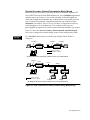
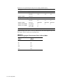
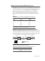
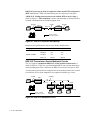
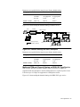
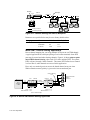
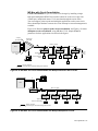
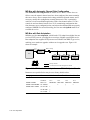
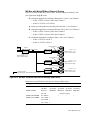
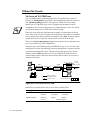
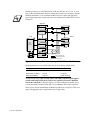
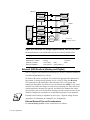
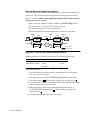
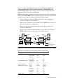
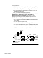
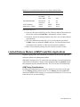
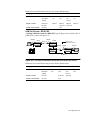
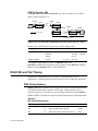
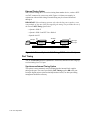
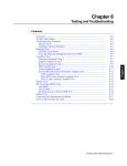
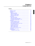
Chapter 6
3512 Operation
Introduction ..................................................................................................
System Applications .....................................................................................
Operating Modes and Network Management Overview ...............................
DDS-I Service ..........................................................................................
Transmission Modes: Overview ..........................................................
Main Channel Transmission Mode Over Point-to-Point Circuits.........
Main Channel Transmission Mode Over Multipoint Circuits .............
Derived Secondary Channel Transmission Mode, Bitstealing .............
Derived Secondary Channel Transmission Mode, Muxed ...................
DDS Secondary Channel (DDS-II SC) Services ......................................
DDS-II SC Transmission Service on Point-to-Point Circuits ..............
DDS II SC Transmission Service Multipoint Circuits .........................
64k Clear Channel (64k CC) Service .......................................................
Time-Division Multiplexing (TDM) .............................................................
TDM and Channel Sharing .......................................................................
TDM and Port-to-Channel Mapping .........................................................
Point-to-Point TDM on DDS-I Type Service .......................................
Point-to-Point TDM & Channel Sharing with DDS-I Service ............
Multipoint TDM and Channel Sharing on DDS-II SC Type Service ..
Mixed TDM - Channel Sharing Applications ......................................
Multipoint TDM and MP-Mux ................................................................
MP-Mux with Non-interruptive Network Management ......................
MP-Mux with Circuit Consolidation ...................................................
MP-Mux with Automatic Channel Rate Configuration .......................
MP-Mux with Rate Adaptation ............................................................
MP-Mux with Mixed TDM and Channel Sharing ................................
TDM and Tail Circuits ..............................................................................
Tail Circuit off 3512 TDM Trunk ........................................................
Tail Circuit Off 3512 TDM in Channel Sharing Mode—DDS-I .........
Tail Circuit Off 3512 TDM in Channel Sharing Mode—DDS-II SC...
Restoral Operation ........................................................................................
Restoral Timing Considerations ...............................................................
Analog Restoral Timing .......................................................................
Digital Restoral Timing .......................................................................
Initiating and Terminating Restoral ..........................................................
Integral Analog Dial Restoral ...................................................................
SLR Automatic Rate-Negotiation Feature ...........................................
Sample SLR Applications ....................................................................
Integral Digital Restoral ...........................................................................
Integral Digital Dial Restoral ...............................................................
Switched-56 and Leased 56k Integral Digital Restoral .......................
External (A/B) Restoral (Analog and Digital) .........................................
External Restoral Tips and Considerations ..........................................
External Restoral Sample Applications ...............................................
6-3
6-3
6-3
6-4
6-4
6-5
6-7
6-7
6-9
6-11
6-11
6-12
6-13
6-14
6-14
6-15
6-18
6-18
6-19
6-20
6-21
6-22
6-23
6-24
6-24
6-25
6-26
6-26
6-27
6-27
6-28
6-28
6-28
6-29
6-29
6-30
6-30
6-31
6-34
6-34
6-35
6-36
6-36
6-38
3512 Operation 6-1
Chapter 6
Contents
Contents (Continued)
Limited Distance Modem (LDM)/Private Wire Applications ......................
LDM Timing Considerations ...............................................................
Tail Circuit Considerations ..................................................................
LDM Tail Circuits - DDS-I ...................................................................
LDM Tail Circuits - DDS-II SC ...........................................................
LDM Tail Circuits - 64k .......................................................................
DSU/CSU and Port Timing ..........................................................................
DSU Timing Options ................................................................................
Network Timing Option........................................................................
Internal Timing Option ........................................................................
External Timing Option .......................................................................
Port Timing................................................................................................
Synchronous/Internal Timing Option ..................................................
Synchronous/External Timing Option .................................................
Synchronous/Station Timing Option ...................................................
Asynchronous Data Timing Option .....................................................
6-2 3512 Operation
6-43
6-43
6-44
6-44
6-45
6-46
6-46
6-46
6-47
6-47
6-48
6-48
6-48
6-49
6-50
6-50
Introduction
This chapter describes how to configure the 3512 DSU/CSU to address your
application requirements most effectively. Configuring applications requires
familiarity with front-panel operation and the menu tree structure.
For more information on...
Front-panel operation, keys, and displays
Configuring the 3512 and 3512 SDC
Refer to...
Chapter 3, The Front Panel
Chapter 4, Configuring the 3512
System Applications
This section explains some of the primary system applications of the 3512:
• Operating Modes and Network Management Overview
• DDS (DDS-I) Services
• DDS Secondary Channel (DDS-II SC) Services
• Point-to-Point Time Division Multiplexing (TDM) and Channel Sharing
• TDM and Port-to-Channel Mapping
• Multipoint Time Division Multiplexing (MP-Mux)
Operating Modes and Network Management Overview
A Motorola 9300 or 9800 Network Management System (NMS) enables you to
manage entire networks from a single central site. This is useful for applications
that require integrated management of Motorola communication devices (3500,
3512, and 3520 DSU/CSUs, and 326X analog modems, multiplexers, and other
system devices). NMS software enables you to:
• Configure, activate, and test communication devices from the central site
• Gather and display performance data
• Track performance problems and evaluate alternate configurations
• Define groups of communication devices to facilitate managing large networks
The NMS uses the network control channel, which it accesses through the NC IN
and NC OUT connectors on a local 3512 rear panel.
The level of network management and control is determined by:
• Digital service type (DDS-I, DDS-II SC or 64k CC)
• Network management mode (Derived Secondary Channel or Normal)
• Circuit configuration (point-to-point or multipoint; single or multiple tier)
The following section explains how network management is supported with various
services, network management modes, and circuit configurations.
3512 Operation 6-3
DDS-I Service
This section describes DDS-I type transmission modes, configurations and
applications. The 3512 supports DDS-I transmission rates of 2.4 to 56 kbps on
point-to-point or multipoint leased digital lines.
With DDS-I, there are three primary modes of network management and control:
• Main Channel (Normal)
• Derived Secondary Channel (BitSteal)
• Derived Secondary Channel (Muxed)
These modes are independent of the host communications protocol. DTE Con
( MODIFY, MODIFY PORT) options specify the mode.
*
Transmission Modes: Overview
In Main Channel (also known as Normal) mode, network management information
is transmitted over the main channel, temporarily interrupting user data. “Normal”
mode, despite its name, should be used only when:
• Your data terminal equipment (DTEs) must transmit at a full rate—one that
exactly equals the line rate
• You do not require network management
Main channel mode buffers network control commands and network polling data,
then transmits them at the full line rate.
In Derived Secondary Channel modes, network management information is
transmitted through Bitstealing or Multiplexing (known as muxing) over a small,
separate part of the total bandwidth, allowing user data to continue without
interruption.
In derived secondary channel modes, the 3512 uses time division multiplexing
(TDM) to maintain the non-interruptive network management channel.
This Mode...
Bitstealing
Muxed
Operates on...
Point-to-Point Circuits
Multipoint Circuits
Point-to-Point Circuits
Multipoint Circuits
And Requires...
—
The MP-Mux feature and a line rate ≥ 9.6 kbps
—
The MP-Mux feature and a line rate ≥ 9.6 kbps
The following sections describe each of the DDS-I transmission modes in detail.
6-4 3512 Operation
Main Channel Transmission Mode Over Point-to-Point Circuits
A point-to-point DDS-I application with a Motorola NMS at the local site is
shown in Figure 6-1. Network control data uses the NC ports and main channel data
uses a DTE port. The DTE port rate and the subscribed line rate are 56 kbps.
56 kbps
DTE
56 kbps
Unit A
56 kbps
Unit B
DDS-I
3512
3512
DTE
Primary Channel
Motorola NMS
Figure 6-1. DDS-I Point-to-Point, Main Channel Mode
Parameters not specified below may be set to factory default values.
Category
Parameter
MODIFY PORT
DTE Con
MODIFY DSU
Data Rate
MODIFY NETWORK
NC Address
*Where x and y are valid addresses
3512 Unit A
Normal
56.0
x*
3512 Unit B
Normal
56.0
y*
Incoming network control data addressed to the local device is buffered and
processed locally. It is not passed out to the DDS-I channel, to prevent unnecessary
main-channel interruption. Incoming network control data addressed for remote
devices is buffered locally and sent as a single message to the remote device(s) at the
DDS-I rate. This causes one interruption to main channel data for the command and
subsequent interruptions for responses.
If necessary, you can further minimize user-data interruptions by taking remote units
off the NMS poll list. (Do not do so unless performance is a problem.) Network
management data then interrupts user data only when the unit is specified. Using this
strategy in point-to-point configurations, circuit or remote device problems cause
Out of Service or Link Down alarms to be sent to the master 3512 and the NMS as it
polls the master. You can then take diagnostic action.
3512 Operation 6-5
Using Circuit Assurance and System Status to Monitor Remote Devices
In some networks, failures at remote units may not have obvious indicators at the
master site. If Circuit Assurance or System Status is enabled in the remote unit, the
NMS can get information about the circuit from the local unit. Circuit Assurance and
System Status cause the remote unit to send only Idles to the master when there is an
error condition. The master can generate an alarm when it receives Idles; for details,
refer to Chapter 4.
Using the NC Mode Parameter to Avoid Network-Management Delay
In multi-tier network management applications, buffering complete messages at the
3512 may cause unacceptable secondary-channel delay due to the effect of buffering
at each tier boundary. To address this concern, use the NC Mode=Passthru option,
which does not buffer control channel data nor inhibit local data from passing down
the DDS line. More interruptions occur since each character is passed independently.
Using an External Multiplexer to Avoid Network-Management Delay
If there is an external multiplexer on the circuit, a multiplexer DTE port can provide
an alternate secondary channel to the remote 3512 or second-tier transmission
devices (Figure 6-2). In this configuration, the NMS monitors the local 3512.
A second NMS connection to a multiplexer DTE port routes NMS polls to the
remote 3512 or second-tier devices.
DTE
DTE
Unit A
Unit B
3512 P1
NC
P1 3512
NC
Multiplexer
(a)
Retransmission:
Off
Multiplexer
Off
(b)
Primary Channel
Secondary Channel
(a) NMS monitors local 3512
(b) Alternate secondary channel to remote
3512 or second-tier device
(b)
Motorola NMS
Figure 6-2. DDS-I Point-to-Point, Network-Managed, Main Channel Mode
Parameters not specified below may be set to factory default values.
Category
MOD IFY DSU
MODIFY NETWORK
6-6 3512 Operation
Parameter
Data Rate
NC Retrans
Unit A
56.0
Off
Unit B
56.0
Off
Main Channel Transmission Mode Over Multipoint Circuits
In a multipoint application, Main Channel mode is used primarily for host polling
(Figure 6-3). The host polls each slave device, and one slave uses the channel at a
time, temporarily interrupting user data. You can take remote units off the NMS poll
list to minimize interruptions, as described above. In this case, the NMS monitors
only the master 3512. NOTE: System Status and CQMS functions do not operate in
this configuration.
If the master displays alarms, you can test remote devices. In this case, remote 3512s
are insensitive to the NMS unless the entire circuit fails. (If so, an Out of Service
alarm occurs.)
9.6 kbps
Unit A
Host
9.6 kbps
DDS-I
3512
Unit B
Unit B
Unit B
3512
3512
3512
DTE
DTE
DTE
9.6 kbps
Motorola NMS
Primary Channel
Secondary Channel
Figure 6-3. DDS-I, Multipoint, Main Channel Mode
Parameters not specified below may be set to factory default values.
Category
MODIFY DSU
Parameter
Data Rate
Unit A
9.6
Unit B
9.6
Derived Secondary Channel Transmission Mode, Bitstealing
SDC only
Bitstealing transmission is available on point-to-point and multipoint circuits.
In Bitstealing mode, the DTE rate is slightly less than the main channel rate, as
shown in Table 6-1; framing and secondary channel requirements use a small part of
the available bandwidth. On a 3512 SDC, Bitstealing is available only when
P3=Direct. (For details, refer to Chapter 4, COMPRESSION category.)
*
Table 6-1.
Port Rates with DDS-1 Bitstealing Mode
Line Rate
(bps)
2400
4800
9600
19200
56000
64000
Available DTE Port Rate
(bps)
2290
4688
9487
19040
55200
62400
3512 Operation 6-7
Point-to-point and multipoint circuits using Bitstealing are shown in Figure 6-4
(A) and (B). If the line rate is 56.0 kbps, the DTE port is allocated 55.2 kbps; framing
and control data use the remaining bandwidth. Most synchronous DTEs and devices,
such as Motorola statistical multiplexers, can operate at these nonstandard port rates.
In this configuration, the 3512s provide a non-interruptive control channel similar to
that of DDS-II SC type service. Bitstealing mode is available for single-channel
applications at 64.0 kbps or subrates.
55.2 kbps
56 kbps
Unit A
DDS-I
3512
DTE
55.2 kbps
Unit B
3512
DTE
Primary Channel
Secondary Channel
Motorola NMS
(A) Point-to-Point Circuit, 3512 in Bitsteal Mode
55.2 kbps
56 kbps
Unit A
DTE
DDS-I
3512
Slave B
Slave C
3512
3512
Motorola NMS
Primary Channel
Secondary Channel
55.2 kbps
(B) Multipoint Circuit, 3512 in Bitsteal Mode
Figure 6-4. DDS-I Derived Secondary Channel Using Bitstealing
Parameters not specified below may be set to factory default values.
Category
Parameter
Point-to-Point Circuit, Figure 6-4(A):
MODIFY DSU
Data Rate
MODIFY PORT
DTE Con
Multipoint Circuit, Figure 6-4(B):
MODIFY DSU
Data Rate
MODIFY PORT
DTE Con
MODIFY NETWORK
NC Address
MODIFY SLV ADDR
Slv-A Addr
Slv-B Addr
*Where x, y, and z are valid addresses
6-8 3512 Operation
Unit A
Slave B
Slave C
56.0
BitSteal
56.0
BitSteal
56.0
BitSteal
56.0
MPM-BitSteal
x*
y*
z*
56.0
56.0
MPS-BitSteal MPS-BitSteal
y*
z*
Derived Secondary Channel Transmission Mode, Muxed
Muxed mode provides a derived secondary channel, but maintains standard DTE
rates for DTEs that require them. With Muxed mode, you can multiplex applications
and data sources on one line, or you can take advantage of favorable digital line
tariffs and to obtain unavailable data rates, without the cost of upgrading front-end
ports or other DTE equipment. Using Muxed mode this way is known as rate
adaptation. For example, with a 3512 is at 56.0 kbps, if an application requires a
lower throughput, you can configure the 3512 to operate at the lower rate.
Rate adaptation is supported over point-to-point and multipoint DDS-1 type circuits.
Figure 6-5 shows the derived secondary channel obtained with Muxed mode.
Ports can be configured as channel sharing or time division multiplexing (TDM).
SDC only
On a 3512 SDC, Muxed mode is available only when P3=Direct. (Refer to
Chapter 4.)
19.2 kbps
56 kbps
Unit A
DDS-I
3512
DTE
19.2 kbps
Unit B
3512
DTE
Primary Channel
Secondary Channel
Motorola NMS
(A) Point-to-Point Derived Secondary Channel Circuit, 3512 in Muxed Mode
9.6 kbps
Unit A
DDS-I
56 kbps
3512
DTE
Slave B
3512
Motorola NMS
Primary Channel
Secondary Channel
Slave C
3512
Port: 1
DTE
9.6 kbps
1
DTE
9.6 kbps
(B) Multipoint Derived Secondary Channel Circuit, 3512 in Muxed Mode
Figure 6-5. DDS-I Derived Secondary Channel Using Multiplexing
3512 Operation 6-9
Parameters not specified below may be set to factory default values.
Category
Parameter
Point-to-Point Circuit, Figure 6-5 (A):
MODIFY DSU
Data Rate
Ch1 Rate
MODIFY PORT
DTE Con
Multipoint Circuit, Figure 6-5 (B):
MODIFY DSU
Data Rate
Ch1 Rate
MODIFY PORT
DTE Con
MODIFY NETWORK
NC Address
MODIFY SLV ADDR
Slv-B Addr
Slv-C Addr
*Where x, y, and z are valid addresses
3512 Unit A
Slave B
Slave C
56.0
56.0
56.0
19.2
19.2
19.2
56.0
9.6
MPM-Mux
x*
y*
z*
56.0
9.6
MPS-Mux
y*
56.0
9.6
MPS-Mux
z*
In Muxed mode, ports can be set to any standard rate. This mode supports up to four
DTE ports; Table 6-2 shows the maximum rates.
Table 6-2.
Maximum Aggregate Transmission Rates in Muxed Mode
Aggregate Port Rate
(kbps)
1.2
4.5
9.0
18.0
55.2
62.4
6-10 3512 Operation
Aggregate Line Rate
(kbps)
2.4
4.8
9.6
19.2
56.0
64.0
DDS Secondary Channel (DDS-II SC) Services
With DDS-II SC type service, the carrier provides bandwidth, over the local loop to
the digital serving office, for a non-interruptive network management channel. This
type of secondary channel is provided on point-to-point and multipoint circuits.
Maximum channel and line rates for DDS-II SC type services are shown in
Table 6-3. (Data framing and carrier control code requirements account for the
differences between aggregate rates and the sums of the primary and secondary
rates.)
Table 6-3.
Transmission Channel Rates with DDS-II SC Type Services
Primary Channel
Secondary Channel
Aggregate Line
(kbps)
(bps)
(kbps)
2.4
133
3.2
4.8
266
6.4
9.6
533
12.8
19.2
1066
25.6
56.0
2667
72.0
NOTE: Some data rates may be unavailable in certain digital serving areas
or configurations. Consult your local carrier for details
DDS-II SC Transmission Service on Point-to-Point Circuits
A DDS-II SC 56-kbps point-to-point circuit is shown in Figure 6-6. An NMS uses
the secondary channel for full-time, non-interruptive circuit and device monitoring.
In multi-tier configurations, the secondary channel can be connected from the remote
3512 to second-tier network-managed Motorola modems and DSUs.
56 kbps
DTE
Unit A
72 kbps
DDS-II SC
3512
Unit B
3512
56 kbps
DTE
Primary Channel
Secondary Channel
Motorola NMS
Figure 6-6. DDS-II SC Point-to-Point Circuit
Parameters not specified below may be set to factory default values.
Category
MODIFY DSU
Parameter
Opmode
Data Rate
Unit A
DDS2
56.0
Unit B
DDS2
56.0
3512 Operation 6-11
DDS-II SC mode may be used in conjunction with a muxed DTE configuration
(DTE Con=Muxed). TDM or channel sharing may be used on up to four ports.
A DDS-II SC 56-kbps point-to-point circuit with the DTE set at 19.2 kbps is
shown in Figure 6-7. Rate adaptation is used to take advantage of 56-kbps tariffs or
to obtain unavailable data rates without upgrade costs.
19.2 kbps
72 kbps
Unit A
Unit B
19.2 kbps
DDS-II SC
3512
DTE
DTE
3512
Primary Channel
Secondary Channel
Motorola NMS
Figure 6-7. DDS-II SC Point-to-Point (Muxed)
Parameters not specified below may be set to factory default values.
Category
MODIFY DSU
Parameter
Opmode
Data Rate
Ch1 Rate
DTE Con
MODIFY PORT
3512 Unit A
DDS2
56.0
19.2
Muxed
3512 Unit B
DDS2
56.0
19.2
Muxed
DDS II SC Transmission Service Multipoint Circuits
The 3512 supports a multipoint DDS-II SC circuit in Main Channel mode, as
shown in Figure 6-8. This way, you obtain standard DTE rates and non-interruptive
network management. This is similar to the DDS-I circuit shown in Figure 6-4 (B).
As with point-to-point multi-tier configurations, the secondary channel can be routed
to second-tier devices. Rate adaptation is not supported with this type circuit.
9.6 kbps
12.8 kbps
Unit A
3512
DTE
DDS-II SC
Motorola NMS
Primary Channel
Secondary Channel
Unit B
Unit D
3512
3512
3512
DTE
DTE
DTE
9.6 kbps
Figure 6-8. DDS-II SC Multipoint Circuit
6-12 3512 Operation
Unit C
Parameters not specified below may be set to factory default values.
Category
MODIFY DSU
Parameter
Opmode
Data Rate
Unit A
DDS2
9.6
Unit B, C, D
DDS2
9.6
NOTE: In DDS-II SC applications at 56 kbps, some data patterns can cause secondary-channel errors. DDS-II service specifies that data must contain a certain density
of 1s; long strings of consecutive 0s are not allowed. If necessary, the network alters
user data to manage 1s density. To prevent this, the 3512 uses the DDS-II SC bit to
insert 1s as needed, which may affect secondary-channel performance. Because of
the need to manage 1s density, 56 kbps DDS-II SC applications are not supported.
64k Clear Channel (64k CC) Service
The 3512 supports the 64 kbps Clear Channel (64k CC) service, as shown in
Figure 6-8. This service, available for point-to-point circuits, allows data
transmission at a line or port rate of 64 kbps. With 64k CC, network management is
available only in the non-interruptive modes (bitstealing and muxed); the bandwidth
available to user applications is approximately 63.2 kbps.
64 kbps
64 kbps
64 kbps
64.0
DTE
3512
DTE
3512
Primary Line
Figure 6-9. 64kbps Clear Channel Circuit
Parameters not specified below may be set to factory default values.
Category
MODIFY DSU
Parameter
Opmode
Unit A
64k CC
Unit B
64k CC
3512 Operation 6-13
Time-Division Multiplexing (TDM)
This section describes time-division multiplexing (TDM), which is available with
DDS-I, DDS-II SC, and 64k CC service, and features that TDM supports:
• Channel sharing
• Port-to-channel mapping
• Multipoint multiplexing (MP-Mux)
The next section shows TDM tail circuits (private-wire, point-to-point applications).
TDM and Channel Sharing
With point-to-point TDM, the 3512 communicates with a mix of DTEs operating at
different transmission speeds. The DTEs might be multiple ports from a single host
computer or front-end processor (FEP); multiple low-speed terminals; or another
DCE device (tail circuit). A multiplexer on the other end of the line divides the
transmissions into component signals and sends them to the terminal ports.
NOTE: TDM uses a small part of the main channel data rate for framing and control
functions.
TDM operates by scanning the unit’s device ports, starting with Port 1. TDM
allocates time slots, called channels, on the main channel to each DTE, interleaving
slots to continuously transmit over the line at a rate up to the sum of the separate
terminal rates. The receiving 3512 distributes the data, by time slot, to its ports.
The 3512 also provides channel sharing. Channel sharing is sometimes known as
port sharing, or a “modem” sharing unit (MSU). The 3512:
• Supports TDM and channel sharing in a number of circuit configurations
• Operates as a single or multiple channel unit
Channel sharing allocates the bandwidth of a TDM channel among some or all of the
3512's ports. You can configure port rates up to 56 kbps (depending on the line rate
and operating mode). Use channel sharing when you have multiple DTEs polled by
one application, in point-to-point or multipoint circuits. In a point-to-point circuit,
channel sharing may be used with:
• Interruptive network management
• Non-interruptive bitstealing
• Rate adaptation
One channel sharing setup can be configured on a 3512.
6-14 3512 Operation
TDM and Port-to-Channel Mapping
Assigning DTE ports to TDM channels forms a port-to-channel map, which
specifies how the 3512 handles the DTEs’ data. In port-to-channel mapping:
• Each 3512 physical port corresponds to a DTE connector
• Each 3512 logical channel corresponds to a TDM time slot
Assigning multiple DTE ports to one TDM channel forms a channel sharing unit.
NOTE: TDM Channels 5 through 8 are not shown in this manual, although you can
assign ports to them on the 3512, for compatibility with 3520 DSU/CSUs.
3520
3512
Figure 6-10 shows how multiplexing uses port-to-channel mapping assignments:
• In Figure 6-10(A), applications A through D assign ports to like-numbered
channels (Port 1 is assigned to Channel 1, and so on)
• In Figure 6-10(B), at the remote site, applications A through D assign ports to
different channels (Port 1 is assigned to Channel 2, and so on)
Port
Host
Computer
or FEP
A
B
C
D
1
2
3
4
Channel
Channel
1
2
3
4
1
2
3
4
3512
Ports: 1 2 3 4
Channels: 1 2 3 4
(Port to Channel Map)
Port
A
B
C
D
1
2
3
4
3512
Co-located
Terminals
Ports: 1 2 3 4
Channels: 1 2 3 4
(Port to Channel Map)
(A) Port-to-Channel Mapping with Same Assignments
Port
Host
Computer
or FEP
A
B
C
D
Channel
1
2
3
4
1
2
3
4
3512
Ports: 1 2 3 4
Channels: 1 2 3 4
(Port to Channel Map)
Channel
2
1
3
4
1
2
3
4
3512
Port
B
A
C
D
Co-located
Terminals
Ports: 1 2 3 4
Channels: 2 1 3 4
(Port to Channel Map)
(B) Port-to-Channel Mapping with Different Assignments
Figure 6-10. Port-to-Channel Mapping Assignments
Sample P-to-Ch options for this configuration are shown in the figure. The map lets
you establish virtual point-to-point links on a multipoint circuit using MP-Mux.
MP-MUX
3512 Operation 6-15
The 3512 uses port-to-channel mapping for circuit consolidation, as follows:
• Figure 6-11 (A) shows a central-site 4-port 3512 and remote 1-port devices
establishing multiple virtual point-to-point circuits
• Figure 6-11 (B) shows polling on Channel 1 to both sites and slaves; and on
Channels 2, 3 and 4, to one site
Port
Channel
A
1
1
B
2
2
C
3
3
D
4
4
56 kbps DDS-I Service
1-Port
3512
1-Port
3512
Ch 2
B
Ports: 1 2 3 4
Channels: 1 2 3 4
A
Ch 1
1-Port
3512
1-Port
3512
Port 1
Port 1
D
Ch 3
C
Port 1
(A) Point-to-Point Circuit Consolidation Using
Multiple 1-Port 3512s at Remote Sites
Port
Channel
A
1
1
B
2
2
56 kbps DDS-I Service
C
3
3
1-Port 3512
D
4
4
Ch 1
Port 1
Ports: 1 2 3 4
Channels: 1 2 3 4
4-Port 3512
Channel Port
1
1
2
2
3
3
4
4
(B) Multipoint Circuit Consolidation Using
1- and 4-Port 3512s at Remote Sites
Figure 6-11. Port-to-Channel Mapping with Circuit Consolidation
6-16 3512 Operation
A
B
C
D
Ch 4
Port 1
Sample P-to-Ch parameters for this configuration are shown in the figure.
NOTES:
3520
1) You can map Channels 1 - 8 to ports, to accommodate 8-channel 3520s.
3512
2) In muxed mode without channel sharing, you may map any combination of
channel numbers to the 3512's ports; you may specify each channel only once.
3) With external (A/B) restoral (on Port 2), to use channel sharing you must map
Port 2 to Channel 2. The 3512 defaults to 0 bandwidth on Channel 2.
4) With channel sharing, Channel 2 cannot be used in a port-to-channel map.
MP-MUX
5) In MP-Mux mode, the master automatically configures slaves’ channel rates to
equal its own. It does so during the training sequence. You may assign
bandwidth to channels for which no port assignment has been made.
You may assign more channels than there are ports in the device (for example,
on a 4-port unit, you may assign bandwidth to any four of the eight channels).
6) Assign unused ports to Channel 0.
Table 6-4 shows the relationship between TDM applications, transmission services
provided, and the circuits they support.
Table 6-4.
TDM and Channel Sharing Applications
Application
TDM
Channel Sharing (Normal mode)
Channel Sharing with Rate Adaptation
Channel Sharing with Bitstealing
Mixed TDM-Channel Sharing
Service
DDS-I
DDS-II SC,
64k CC
DDS-I
DDS-II SC,
64k CC
DDS-I
DDS-II SC,
64k CC
DDS-I
DDS-II SC,
64k CC
DDS-I
DDS-II SC,
64k CC
Circuit Available
Point-to-Point, Multipoint
Point-to-Point
Point-to-Point, Multipoint
Point-to-Point, Multipoint
Point-to-Point, Multipoint
Point-to-Point
Point-to-Point, Multipoint
Point-to-Point
Point-to-Point, Multipoint
Point-to-Point
3512 Operation 6-17
Point-to-Point TDM on DDS-I Type Service
A 4-port 3512 with TDM in Muxed mode and 56-kbps DDS-I type service is
shown in Figure 6-12. With this service, the 3512 offers aggregate port rates up to
55.2 kbps, whether or not the derived secondary channel is required for network
management. All ports support synchronous rates to 48 kbps and asynchronous rates
to 19.2 kbps, except 16.8 kbps. Synchronous and asynchronous data can be mixed.
Any port can be configured for either EIA/TIA 232-D or V.35 interfaces.
The available rates are the same with DDS-I and DDS-II SC type services. DDS-II
SC with TDM provides no advantage over DDS-I, since a non-interruptive
management channel is provided in either case.
1
56 kbps
Unit A
DTE
3512
4
1
Unit B
DDS-I
DTE
3512
4
DTE
DTE
Primary Channel
Secondary Channel
Motorola NMS
Figure 6-12. Point-to-Point TDM, DDS-I Type Service
Parameters not specified below may be set to factory default values.
Category
MODIFY DSU
Parameter
Data Rate
CHn Rate
DTE Con
MODIFY PORT
Unit A
56.0
As appropriate
Muxed
Unit B
56.0
As appropriate
Muxed
Point-to-Point TDM & Channel Sharing with DDS-I Service
The 3512 supports channel sharing applications with contention controlled by the
host communication protocol. One to four DTEs can contend for the assigned
channel (2.4, 4.8, 9.6, 19.2, or 56 kbps). Figure 6-13 shows point-to-point channel
sharing in. Since all remote DTEs share one channel, the port-to-channel map
is 1111.
Port 1
Port 1
DTE
Unit A
Unit B
DTE
DDS-I 56 kbps
3512
3512
DTE
Port 4
Motorola NMS
Primary Channel
Secondary Channel
Figure 6-13. Point-to-Point TDM with Channel Sharing, DDS-I
6-18 3512 Operation
Parameters not specified below may be set to factory default values.
Category
MODIFY DSU
Parameter
Unit A
Data Rate
56.0
Ch1 Rate
As appropriate
P-to-Ch
1234*
MODIFY PORT
DTE Con
Muxed
*Local Ports 2, 3, and 4 are not used in the example.
Unit B
56.0
As appropriate
1111
Muxed
Figure 6-14 shows multipoint channel sharing on DDS-I service.
Unit A
Port 1
DDS-I 56 kbps
DTE
3512
Unit D
Unit B
3512
3512
Unit C
3512
Motorola NMS
Primary Channel
Secondary Channel
Port:
DTE
DTE
1
4
DTE
Port:
DTE
DTE
1
4
DTE
1
4
Figure 6-14. Channel Sharing with DDS-I, Multipoint
Parameters not specified below may be set to factory default values.
Category
MODIFY DSU
MODIFY PORT
Parameter
Data Rate
Ch1 Rate
P-to-Ch
DTE Con
Unit A
56.0
As appropriate
1234
Muxed
Unit B, C, D
56.0
As appropriate
1111
Muxed
Multipoint TDM and Channel Sharing on DDS-II SC Type Service
With a carrier-provided secondary channel service, port rates to 56 kbps are
supported with non-interruptive network management over a point-to-point circuit.
Line rates up to 19.2 kbps are supported over multipoint circuits.
Figure 6-15 shows multipoint channel sharing with DDS-II SC type service.
3512 Operation 6-19
9.6 kbps
Port 1
12.8 kbps
Unit A
DDS-II SC
3512
DTE
Unit B
Unit D
3512
3512
Unit C
Port: 1
4
1
4
DTE
DTE
3512
DTE
Motorola NMS
DTE
Primary Channel
Secondary Channel
1
4
DTE
DTE
Figure 6-15. Channel Sharing with DDS-II, Multipoint
Parameters not specified below may be set to factory default values.
Category
MODIFY DSU
Parameter
Opmode
Data Rate
P-to-Ch
Unit A
DDS2
9.6
1234
Unit B, C, D
DDS2
9.6
1111
Mixed TDM - Channel Sharing Applications
Port-to-channel mapping lets you assign multiple DTE ports to one TDM channel.
A typical application has a host port polling several remote terminals. Some DTE
ports may be muxed and others sharing channels. Figure 6-16 shows point-to-point
mixed TDM-channel sharing, where both 3512s have multiple DTEs. The remote
DTEs on Ports 1 through 3 share Channel 1. The remote DTE on Port 4 uses Channel
2 to local Port 2; other channels are not used in this application.
Here, only one terminal (port) can access the shared channel at any one time.
When terminals contend, priority is given to the lowest-numbered port.
DTEs
Channel-Sharing
Unit
Port
9.6
2.4
kbps
Host
Computer
or FEP
1
2
3
4
Channel
Channel
1
2
3
4
Unit A
DDS-I
19.2 kbps
Port
1
2
3
1
2
4
Unit B
Ports: 1 2 3 4
Ports: 1 2 3 4
TDM Channels: 1 2 3 4
TDM Channels: 1 1 1 2
(Port to Channel Map)
Figure 6-16. Mixed TDM-Channel Sharing Application
6-20 3512 Operation
3 Polled Terminals
Sharing
Channel 1
DTE
Parameters not specified below may be set to factory default values.
Category
MODIFY DSU
MODIFY PORT
Parameter
Data Rate
Ch1 Rate
Ch2 Rate
P-to-Ch
DTE Con
Unit A
19.2
9.6
2.4
1234
Muxed
Unit B
19.2
9.6
2.4
1112
Muxed
Multipoint TDM and MP-Mux
MP-Mux extends the 3512’s multiplex features to enable you to operate several
multipoint and point-to-point applications on one multipoint circuit.
MP-MUX
An MP-Mux network consists of one master (control) DSU/CSU and a number of
slave (tributary) DSU/CSUs. Master and slave devices are connected by multipoint
junction units (MJUs) within the digital network. Devices transmit as follows:
• The master multiplexes data from its DTEs, and transmits it over the DDS line
to the MJU. The MJU broadcasts to the slaves. The slaves demultiplex the data
to the appropriate DTE ports.
• Each slave multiplexes data from its DTEs, and transmits it over the DDS line
to the MJU. The MJU combines the data and sends it over the DDS line to the
master. The master demultiplexes the data and sends it to the appropriate ports.
Up to 20 slaves can be attached to one master 3512. A maximum of 64 DTEs can be
connected in a multipoint application. MP-Mux is supported on DDS-I type service
only, in two operating modes:
• Bitstealing: single channel with non-interruptive network control channel
• Muxed: multi-channel with non-interruptive network control channel
3512 Operation 6-21
MP-Mux with Non-interruptive Network Management
MP-Mux allows non-interruptive network management of DDS-I multipoint circuits.
Using a bitstealing mode or MP-Muxed rate adaptation provides the bulk of available bandwidth to a multipoint application while reserving a small portion for network management. Figure 6-17 shows a multipoint application with noninterruptive network management.
To 55.2
kbps
Unit A
DDS-I 56 kbps
3512
Host
Unit B
Unit C
Unit D
3512
3512
3512
To 55.2 kbps
To 55.2 kbps
To 55.2 kbps
Motorola NMS
Primary Channel
Non-Interruptive Network Management Channel
Figure 6-17. MP-Mux Application with Non-interruptive Network Management
Parameters not specified below may be set to factory default values.
Category
MODIFY DSU
MODIFY PORT
6-22 3512 Operation
Parameter
Data Rate
Ch1 Rate
DTE Con
Unit A
56.0
As appropriate
MPM-Mux or
MPM BitSteal
Unit B, C, D
56.0
As appropriate
MPS-Mux or
MPS-BitSteal
MP-Mux with Circuit Consolidation
Circuit consolidation lets you save local access charges by installing a single
high-speed multiplexed DDS-I line from the central site to the service provider.
A multi-port, multiplexed master 3512 routes data through the carrier office.
You can configure point-to-point and multipoint applications on the same circuit.
Slaves demultiplex the data at remote sites. Non-interruptive network management is
available.
Figure 6-18 illustrates point-to-point circuit consolidation, and Figure 6-19 shows
multipoint circuit consolidation, using MP-Mux 3512s. Sample P-to-Ch
parameters for these applications are shown in the figures.
9.6 kbps
per Channel
Host
A
B
C
D
E
3520 8-Port
MP TDM
1-1
2-2
3-3
4-4
5-5
DDS-I 56 kbps
Port-to-Channel
Map
Application:
Rate:
Port-to-Channel
Map:
3512
3512
3512
A
C
E
9.6
1
9.6
3
3512
B
D
9.6
Motorola NMS
9.6
5
3512
1-Port
Slave
3512s
9.6
2
4
Primary Channel
Non-Interruptive Network Management Channel
Figure 6-18. MP-Mux for Circuit Consolidation on Multiple Point-to-Point Circuits
A
Host
Motorola NMS
B
DDS-1 56 kbps
3512
Master
3512
Slave A
Application:
Port-to-Channel Map:
A
1
3512
Slave B
A
1
3512
Slave C
3512
Slave D
B
B
2
2
Primary Channel
non-interruptive Network Management Channel
Figure 6-19. MP-Mux for Circuit Consolidation on Multiple Multipoint Circuits
3512 Operation 6-23
MP-Mux with Automatic Channel Rate Configuration
With automatic rate configuration, the master device “trains” remote slaves as
follows: once the master's channel rates have been configured, the master transmits
the rates to slaves. Slaves compare their settings with those from the master, and if
necessary, modify their configuration to match the master's. This is particularly
useful in a circuit consolidation application. With a four-channel master 3512 at a
central site and one-channel remote slave 3512s, transmitting configuration data
from the master saves configuration time, and ensures that the data paths are properly
configured. NOTE: For successful training, the line rates and Opmode must be set
to match the service.
MP-Mux with Rate Adaptation
MP-Mux provides rate adaptation, which lets the 3512 adapt from a higher line rate
to a lower DTE port rate, providing the cost savings of higher-speed digital service.
Rate adaptation also supports DTE port rates not available from DDS-I type service,
enabling you to make rate upgrades without service upgrade costs. Figure 6-20
shows an example.
19.2
kbps
DDS-I 56 kbps
3512
Master
Host
Motorola NMS
Slave B
3512
Slave C
3512
Slave D
3512
19.2 kbps
19.2 kbps
19.2 kbps
Primary Channel
non-interruptive Network Management Channel
Figure 6-20. MP-Mux for Rate Adaptation over DDS-I Multipoint Circuits
Parameters not specified below may be set to factory default values.
Category
MODIFY DSU
Parameter
Data Rate
Ch1 Rate
MODIFY PORT
DTE Con
MODIFY NETWORK NC Address
MODIFYSLV ADDR Slv-A Addr
Slv-B-Addr
Slv-C Addr
6-24 3512 Operation
Unit A
56.0
19.2
MPM-Mux
x
y
z
Slave B
56.0
19.2
MPS-Mux
x
Slave C
56.0
19.2
MPS-Mux
y
Slave D
56.0
19.2
MPS-Mux
z
MP-Mux with Mixed TDM and Channel Sharing
Figure 6-21 shows an MP-Mux, mixed TDM - channel sharing environment, with
four applications, P, Q, R, and S:
• P, a multipoint application extending to Remote Sites 1 and 2, uses Channel 1
— At Site 1, DTEs on Ports 1 and 2 share Channel 1
— At Site 2, a DTE is on 3512 Port 3
• Q, a point-to-point application extending to Remote Site 1, uses Channel 2
• R, a multipoint application extending to Remote Sites 2 and 3, uses Channel 3
— At Site 2, DTEs on Ports 1 and 2 share Channel 3
— At Site 3, DTEs on Ports 1 and 2 share Channel 3
• S, a multipoint application extending to Sites 1 and 2, uses Channel 4
— At Site 1, a DTE is on Port 4
— At Site 2, a DTE is on Port 4
P
Q
R
S
Unit A
Channel-Sharing
Unit
DDS-I 56 kbps
4-port 3512
Ports: 1 2 3 4
TDM Channels: 1 2 3 4
(Port to Channel Map)
P
P
4-port 3512
Site 1 - Unit B
Channel-Sharing
Unit
Q
S
R
R
4-port 3512
Site 2 - Unit C
Channel-Sharing
Unit
Primary Channel
Non-Interruptive Network Management Channel
4-port 3512
Ports: 1 2 3 4
TDM Channels: 1 1 2 4
(Port to Channel Map)
P
Ports: 1 2 3 4
TDM Channels: 3 3 1 4
(Port to Channel Map)
S
R
R
Ports: 1 2 3 4
TDM Channels: 3 3 0 0
(Port to Channel Map)
Site 3 - Unit D
Figure 6-21. MP-Mux for Mixed TDM-Channel Sharing Applications
Parameters not specified below may be set to factory default values.
Category
MODIFY DSU
MODIFY PORT
MODIFY NETWORK
MODIFY SLV ADDR
Parameter
Data Rate
Chn Rate
DTE Con
P-to-CH
NC Address
Slv-A Addr
Slv-B-Addr
Slv-C Addr
Unit A
56.0
As needed
MPM-Mux
Slave B
Slave C
56.0
56.0
As needed As needed
MPS-Mux MPS-Mux
[shown in figure]
x
y
Slave D
56.0
As needed
MPS-Mux
z
x
y
z
3512 Operation 6-25
TDM and Tail Circuits
Tail Circuit off 3512 TDM Trunk
The 3512 TDM supports analog and digital tail circuit applications as shown in
Figure 6-22. Timing buffers for each port accommodate phase differences between
tiers. Inband signaling with DTEs also supported. TDM’s derived secondary
channel (for use with DDS-I type services) supports non-interruptive network
management. Tail circuits can be private-wire, limited-distance circuits. For details
on tail circuit timing, refer to “DSU/CSU and Port Timing.”
With a tail circuit from one digital network to another, occasional data errors may
occur: when each 3512 derives timing from its digital network and the two networks
are not synchronized, slight variations accumulate to cause slips. In general, digital
circuits from one service provider with one master clock do not incur slips.
The level of network management supported in second-tier devices depends on the
service type and the tail circuit configuration.
Not shown is the 3512 TDM operating with DDS-II SC type service over the trunk
and digital tail circuits. Non-interruptive network management is supported in pointto-point and multipoint tail circuits. The tail circuits can be private-wire, limiteddistance circuits. NOTE: Second-tier 3512s set to DDS-II SC mode cannot use
external-timing options. Slips occur unless the first and second tier services have a
common clock source.
DTE
Port
1
1
Unit A
Unit B
DDS-I 56 kbps
DTE
4
3512
2
3512
Analog
Service
Modem
3512
Digital
Service
3 DTE
Motorola NMS
Primary Channel
Secondary Channel
Crossover Cable
4 DTE
Port-to-Channel Map: 1
Figure 6-22. Tail Circuit Off 3512 TDM
Parameters not specified below may be set to factory default values.
Category
MODIFY DSU
MODIFY PORT
6-26 3512 Operation
Parameter
Data Rate
Chn Rate
DTE Con
P-to-CH
Unit A
Unit B
56.0
56.0
As needed
As needed
Muxed
Muxed
[shown in figure]
2
3 4
Tail Circuit Off 3512 TDM in Channel Sharing Mode—DDS-I
The 3512 TDM in channel sharing mode supports tail circuit applications
(Figure 6-23). When used with a Motorola NMS, network management commands
are data-interruptive. The maximum port rate is 56 kbps. For details on tail circuit
timing, refer to “DSU/CSU and Port Timing.”
Port
1
DTE
1
DDS-I 56 kbps
3512
2
3512
Analog
Service
Modem
3512
Digital
Service
3 DTE
Motorola NMS
Primary Channel
Secondary Channel
Crossover Cable
4 DTE
Port-to-Channel Map: 1
1
1 1
Figure 6-23. Tail Circuit Off 3512 TDM, Channel Sharing Mode–DDS-I
Parameter options for the setup in Figure 6-23 are the same as those for Figure 6-22,
except for P-to-CH, which is 1111.
Tail Circuit Off 3512 TDM in Channel Sharing Mode—DDS-II SC
With DDS-II SC type service, the carrier provides a secondary channel for network
management. The maximum port rate is 56 kbps. NOTE: Second-tier 3512s set to
DDS-II SC mode cannot use external-timing options. Slips occur unless the first and
second tier services have a common clock source.
DDS-II SC service applications may be configured as shown for DDS-I in
Figure 6-23. The level of network management supported in the second-tier devices
depends on the service type and the tail circuit configuration.
This ends the discussion of TDM on DDS-I and DDS-II SC type circuits. The next
section addresses restoral operation on the 3512.
3512 Operation 6-27
Restoral Operation
This section explains the 3512 restoral features, which enable the 3512 to continue to
operate in the event of DDS line failure:
• Restoral timing considerations
• Initiating and terminating restoral
• Analog restoral (always dial)
• Digital restoral, dial and leased
The following rules apply to restoral:
• In muxed modes, a network management uses a derived secondary channel
• To initiate restoral automatically, you must set DDS to Dial=Auto
• Only the 3512 that initiated the restoral session can automatically terminate it
• Bitstealing mode is not supported
Restoral Timing Considerations
For most restoral applications, there should be one clock source for the system.
The following recommended configurations ensure exactly one source.
NOTE: These recommendations also apply to devices that do not allow external port
timing.
Analog Restoral Timing
• With Integral Restoral
1) Set one 3512 to Timing=Internal ( RESTORAL, RESTORAL CONFIG), so
that it derives transmit timing from its internal oscillator.
*
2) Set the other 3512 to Timing=Loopback (RESTORAL CONFIG), so that it
derives transmit timing from received data.
• With A/B Restoral
1) Set one 3512 to Timing=Internal (RESTORAL CONFIG), so that it derives
transmit timing from its internal oscillator.
2) Set the other 3512 to Timing=Ext P2 (RESTORAL CONFIG). This has the
effect of setting Port 2 to Sync Ext, so it accepts timing on Pin 24.
3) Set both devices’ port and transmitter to Timing=External (RESTORAL
CONFIG).
6-28 3512 Operation
Digital Restoral Timing
The following configurations are recommended, to ensure only one clock source.
• With integral digital restoral, set both 3512s toTiming=Network
• With external digital restoral, set both restoral devices to
Timing=Ext P2 St
• With switched digital restoral devices, set both restoral devices for
network timing
• With other restoral services, set one device for internal timing and the
other for loopback timing
Initiating and Terminating Restoral
If line failure occurs, restoral can be initiated as follows:
• Automatically
— Based on user-defined failure parameters
— By answering a call
— By responding to a DTR EIA signal on Port 1
• Manually, from the 3512 front panel or a network management system
Operation is returned to the primary line in one of three ways:
• Automatically, after user-defined criteria have been met and the line has been
good for a user-specified period of time
• After a user-specified terminate timer has expired
• Manually, from the front panel or a network management system
• By responding to a DTR EIA signal on Port 1
If automatic termination is enabled, the 3512 monitors the primary line periodically.
If it is clear of alarms for a user-specified period of time, restoral is automatically
terminated and data transmission returns to the primary line.
3512 Operation 6-29
Integral Analog Dial Restoral
Integral single line restoral (SLR) can automatically restore data transmission over
the Public Switched Telephone Network (PSTN) in the event of primary-line failure.
SLR operates in the V.32 and V.32 bis modes.
SLR Automatic Rate-Negotiation Feature
Automatic rate negotiation enables the unit to adapt its line rate to that of another
unit. It operates as follows: during the training sequence at the start of restoral, each
device transmits its configured line rate (the Rest Rate parameter option) to the
other. The initiating device establishes a connection. If the Rest Rate values are not
equal, they use the lower rate. For example, if a 3512 with Rest Rate=14.4 kbps
trains with another at 9.6, the resulting line rate is 9.6. This function lets a 3512
access a restoral pool, such as a mix of 14.4 kbps V.32 bis and 9.6 kbps V.32
modems.
In single-channel operations (where DTE Con=Normal), rate negotiation sets Port
1’s line rate in accordance with the negotiated rate.
In TDM applications, (DTE Con=Muxed), rate negotiation subtracts bandwidth
from the assigned channels, until their aggregate bandwidth matches the available
bandwidth. Negotiation starts at the highest-numbered channel that is assigned
bandwidth, decrementing in the following steps: 14.4, 12.0, 9.6, 7.2, 4.8, 2.4, 1.2, 0.
It continues subtracting from the highest-numbered channel rate until the total
bandwidth is less than the restoral line rate. If the rate reaches zero without matching
the restoral line rate, the 3512 selects the next-highest-numbered channel and
subtracts as above.
Example 1: A local 3512 with Rest Rate=14.4, and remote unit with
Rest Rate=12.0. The local unit is configured as follows:
Channel
1
2
3
4
Rate (kbps)
4.8
2.4
2.4
2.4
The local unit initiates restoral and negotiates a line rate of 12.0, and its Channel 4
rate changes to 1.2 kbps.
Example 2: A local 3512 with Rest Rate=14.4, and remote unit with
Rest Rate=9.6. The local unit is configured as above. The local unit initiates restoral
and negotiates a line rate of 9.6, and its channel rates become:
Channel
1
2
3
4
6-30 3512 Operation
Rate (kbps)
4.8
2.4
1.2
0.0
Sample SLR Applications
A sample point-to-point digital circuit with integral SLR in a standalone 3512 is
shown in Figure 6-24. Normal operation is over the 56 kbps circuit; SLR uses a 14.4
kbps dial line. An NMS and a NetView manage the system over a secondary channel.
If the DDS line runs at:
• Up to 9.6 kbps, SLR can restore the entire bandwidth
• More than 9.6 kbps, SLR can restore a maximum bandwidth of 14.4 kbps
Host
with
NetView
Unit A
56 kbps DDS Service
3512
SLR
Unit B
DTE
3512
SLR
NM
14.4 kbps
PSTN
14.4 kbps
Motorola NMS
Leased Line (for regular operation)
Secondary Channel
Restoral Line
Figure 6-24. Point-to-Point Circuit, Integral SLR, Standalone 3512
Restoral parameters not specified below may be set to factory default values.
Category
AUTO ANSWER
RESTORAL CONFIG
PHONE NUMBER
Parameter
Answer
Timing
Enter Phone#
Unit A
Unit B
Enable
Loopback
[phone number]
A sample point-to-point digital circuit with integral SLR in an alternatedestination restoral pool is shown in Figure 6-25. This configuration enables you to
re-route data traffic around a failed node. The restoral pool devices can establish a
connection to any of the remote devices.
3512 Operation 6-31
Normal operation is over the DDS circuit; SLR uses dial lines at 9.6, 12.0, or 14.4
kbps. A Motorola NMS and a NetView manage the system over a secondary channel.
Installing standalone 3512s in a Motorola Mini-Nest saves space and aggregates
power requirements into a single outlet (for more information on Mini-Nests, refer to
Chapter 2).
Mini-Nest
3512
3512
SLR
3512
3512
SLR
Local
Host
with
NetView
Remote
3512
3512
SLR
3512
3512
SLR
Unit B
3512
SLR
3512
SLR
Motorola NMS
Unit A
PSTN
Primary DDS Line
Secondary Channel
Restoral Line
Figure 6-25. Point-to-Point Circuit, Integral SLR, 3512s in Mini-Nest
Restoral parameters not specified below may be set to factory default values.
Category
AUTO ANSWER
RESTORAL CONFIG
PHONE NUMBER
Parameter
Answer
Timing
Enter #1
Unit A
Enable
Unit B
Loopback
[phone number]
An application using a mix of 3520s, 3512s, and 3260s on point-to-point digital
circuits with integral SLR at the remote sites, and A/B restoral in a Modulus
Nest at the central site is shown in Figure 6-26. This configuration enables you to
re-route data traffic around a failed node. Using a Modulus Nest at the central site
allows you to mix and match Motorola Modulus products in a single nest. This saves
space and aggregates power requirements into a single outlet.
6-32 3512 Operation
To obtain secondary-channel network management in this mixed configuration, you
must use Muxed mode. Regular operation is over the DDS circuit; SLR uses dial
lines at 9.6, 12.0, or 14.4 kbps.
Unit A
Modulus Nest
3520
Host
3260
Unit B
56 kbps
56 kbps
3512
SLR
3512
SLR
3520
3260
PSTN
Primary DDS Line
Restoral Line
Figure 6-26. Point-to-Point Circuit, Integral SLR, Modulus Product Mix
Restoral parameters not specified below may be set to factory default values.
Category
DIAL PARAMETERS
AUTO ANSWER
RESTORAL CONFIG
Parameter
DDS to Dial
Answer
Timing
Unit A
Man
Ext.P2
Unit B
Enable
Loopback
NOTE: The 3512 provides a secondary channel when Restoral DTE=Normal.
When Restoral DTE=Muxed, the secondary channel is multiplexed with the main
channel. If you are not restoring to another 3512, and DTE=Normal, set NC
Restoral= Off, since this separate channel may interfere with the main channel.
Similarly, other devices' secondary channel implementation may interfere with the
3512. To avoid interference, disable those devices’ secondary channels.
In the above application, if the circuit is not managed by an NMS and the 3512 is
configured for Normal mode, NC Restoral must be set to Off. If the circuit is
managed by an NMS and the 3512 is configured for Muxed, then the 3260's
secondary channel must be disabled.
3512 Operation 6-33
Integral Digital Restoral
Integral digital restoral can automatically restore data transmission over 56 kbps
DDS-I leased-line or 4-wire SW 56 service. If a line failure occurs, as described later
in this section, restoral can be initiated and terminated as described above. Digital
restoral is also terminated when the 3512 receives Idles on the alternate line.
Non-interruptive network management is not available.
For 3512s configured with integral digital restoral: when LD Detect=Off and the
service provider does not supply sealing current, the 3512 cannot detect a link down
on the restoral line. Thus, when configured for integral digital restoral, set LD
Detect=On so the 3512 can detect restoral-line failure. (Refer to Chapter 4.)
Integral Digital Dial Restoral
A sample point-to-point switched 56 kbps (SW 56) integral-restoral circuit is
shown in Figure 6-27. A Motorola NMS operates over a secondary channel.
Host
Unit A
56 kbps DDS Service
3512
SW56
Unit B
3512
SW56
NM
56 kbps
Switched
Digital
Network
DTE
56 kbps
Motorola NMS
Leased Line (for primary operation)
Secondary Channel
Restoral Line
Figure 6-27. Switched Digital Point-to-Point Circuit, Integral Restoral
Figure 6-27 shows a point-to-point restoral circuit with integral SW 56 service at
one end and A/B restoral at the other. Normal operation is over a leased circuit.
A 3512 with the SW 56 feature can initiate or receive a call from the remote SW 56
device to restore a broken connection. NOTE: The SW 56 device may run on either a
2-wire or 4-wire service.
Restoral parameters not specified below may be set to factory default values.
Category
AUTO ANSWER
PHONE NUMBER
6-34 3512 Operation
Parameter
Answer
Enter Phone #
Unit A
[phone number]
Unit B
Enable
56 kbps
FEP
3512
SW56
DTE
35XX
A/B
56 kbps
4-Wire Line
SW56
Switched
Digital
Network
Standalone
SW56
SW56
Data Device
2 or 4-Wire Line
Figure 6-28. Switched Digital Point-to-Point Circuit, Mixed Restoral
Restoral parameters not specified below may be set to factory default values.
Category
PHONE NUMBER
RESTORAL CONFIG
Parameter
Enter Phone #
Rest Type
Unit A
Unit B
[phone number]
Digital
Switched-56 and Leased 56k Integral Digital Restoral
An integral digital leased-line restoral application on a point-to-point circuit is
shown in Figure 6-29.
Motorola NMS
Front
End
Processor
56k DDS
3512
DDS
Leased Line
Restoral Line
56 kbps DDS
3512
DDS
56 kbps DDS-1
Leased Line
DTE
Figure 6-29. Leased 56K Integral Digital Restoral, Point-to-Point
Restoral parameters not specified below may be set to factory default values.
Category
DIGITAL CONFIG
Parameter
Call Control
Unit A
DDS
Unit B
DDS
An integral digital restoral pool application on multiple point-to-point circuits
is shown in Figure 6-30.
3512 Operation 6-35
Mini-Nest
3512
3512
SW56
3512
3512
SW56
Remote
Host
3512
3512
SW56
3512
3512
SW56
Unit B
3512
SW56
Switched
Digital
Network
Primary Line
Secondary Channel
Restoral Line
3512
SW56
Motorola NMS
Unit A
Figure 6-30. Switched 56K Integral Digital Restoral, Pool on STAT Mux
Restoral parameters not specified below may be set to factory default values.
Category
AUTO ANSWER
RESTORAL CONFIG
DIGITAL CONFIG
PHONE NUMBER
Parameter
Answer
Timing
Call Control
Enter Phone #
Unit A
Enable
Unit B
Loopback
DDS
DDS
[phone number]
External (A/B) Restoral (Analog and Digital)
The 3512 supports dial restoral to an external device, such as a 326XFAST modem or
a Switched Digital Data Service device.
To initiate A/B restoral, a multiport 3512 switches the aggregate data channel from
the port that is connected to the primary line (A) to Port 2, using its A/B switch.
The external device (B) establishes a dial connection. The 3512 resumes data
transmission through the external device over an alternate line. NOTE: 3512s cannot
fall back to accommodate changes in a dial device's operating rate. If the dial device
cannot maintain the alternate-line data rate, and falls back to maintain the connection, the data is passes will be unreliable and may cause the restoral session to be terminated. Configure the external device so that fallback operation is not supported.
External-restoral cabling is dependent on device type—digital or analog. Refer to
Appendix A for information on cabling for your configuration.
External Restoral Tips and Considerations
For external analog restoral, set the external devices as follows:
6-36 3512 Operation
• Enable PSTN Cleardown at both V.32 modems
• Disable Auto Call Unit (ACU)
• Set the DTE rate to equal the analog data rate
• Set Flow Control to Off
• Set Speed Conversion to Off
• Set DTR to Tail (where the modem initiates the dial call on DTR off-to-on
transition, drops the call on a DTR on-to-off transition, and answers the call
regardless of the state of DTR), or to 108.1 (if the modem originates only)
• Configure for Sync Mode and Sync Data (typically)
• Set Timing to External
• Set DCD to Low, except when in Data Mode
• Set RT to Always High
• Disable Fallback
For external switched-digital restoral, set device parameters as follows:
• Dial on a DTR off-to-on transition
...And set the answering device’s parameters as follows:
• Set Auto Answer to Enable
NOTE: Some vendors’ devices cannot answer and originate restoral calls.
3512 Operation 6-37
External Restoral Sample Applications
In the following examples, Unit A and Unit B represent the local and remote 3512s,
respectively. This section also provides suggestions for setting up restoral timing.
Figure 6-31 shows a point-to-point application with manually-initiated external
analog restoral. In this example:
• Units A and B are running at 56 kbps in DDS-I, with DTE Config=Normal
• The operator sets 3512 unit A as the originate-only unit
• The operator designates unit B as the answer unit
• Restoral is initiated and terminated manually at a data rate of 24.0 kbps
56 kbps
DTE
24 kbps
56 kbps
Unit A
DDS-I
Local
3512
PSTN
326x FAST
Unit C
24 kbps
56 kbps
Unit B
Remote
3512
DTE
326x FAST
24 kbps
Unit D
Primary Line
Alternate Line
Figure 6-31. Point-to-Point, Analog External Restoral
Restoral parameters not specified below may be set to factory default values.
Category
AUTO ANSWER
RESTORAL CONFIG
Parameter
Answer
Timing
Rest Rate
Unit A
24
Unit B
Enable
Ext P2
24
Operational Sequence:
1) The operator notices an alarm condition, signalling the loss of the primary
line, on the unit A front panel.
2) The operator displays ACTIVATE RESTOR ( RESTORAL main menu).
*
3) The operator presses
. When Initiate? displays, the operator presses
.
4) Unit C dials and establishes a connection with Unit D. Communication begins
over the analog alternate line at 9.6 kbps.
5) When the primary line has been reestablished, the operator displays
ACTIVATE RESTOR, then presses
. When Terminate? displays, the
operator presses .
6) Communication should return to the primary line.
6-38 3512 Operation
Figure 6-32 shows a point-to-point, muxed, network-managed application,
where communication is restored, either manually or automatically, to an
external analog device. In this example, restoral is initiated automatically when
either unit receives a Link Down or DDS alarm.
NOTE: In this example, either unit can initiate or terminate restoral. To automatically
initiate restoral, From DDS must be set to different options, such as 15 seconds and 60
seconds, in units A and B, to minimize call collision. In this example:
• Units A and B run at 56 kbps in DDS-II, with Ports 1 and 3 configured to
operate at 9.6 kbps on the restoral line
• Both units are configured for muxed-mode restoral. NOTE: Port 3 cannot be a
tail circuit in this type of configuration.
• Restoral is set to auto initiate in both 3512s when a link goes down or in
response to DDS alarms
• Restoral is set to terminate either manually, or by the timer, after four hours
NOTE: NMS remains in effect when a 3512 initiates restoral.
9.6
kbps
DTE
DTE
9.6 kbps
9.6 kbps
DTE
56 kbps
Port 1
Port 3
Port 2
Motorola NMS
DDS-II
Local
3512
Unit A
Remote
3512
Unit B
326x FAST
PSTN
Unit C
Port
1
3
2
9.6 kbps
326x FAST
24.0 kbps
DTE
Primary Line
Secondary Channel
Alternate Line
Unit D
Figure 6-32. Point-to-Point, Muxed Analog External Restoral (with NMS)
Parameters not specified below may be set to factory default values.
Category
DIAL PARAMETERS
INIT PARAMETERS
AUTO ANSWER
RESTORAL CONFIG
MODIFY DSU
Parameter
DDS to Dial
Dial to DDS
Trm Tmr
From DDS
DDS Alarm
Link Down
Answer
DTE
Timing
Ch1 Rate
Ch 2 Rate
Rest Rate
Opmode
Unit A
Auto
Auto
4 hrs
On
On
Enable
Muxed
9.6
9.6
24.0
DDS-II
Unit B
Auto
Auto
60
On
On
Enable
Muxed
Ext P2
9.6
9.6
24.0
DDS-II
3512 Operation 6-39
Operational Sequence:
1) Unit A or B automatically initiates restoral if the link goes down, or if an Out
of Service, Out of Sync, or ABN Station Code is present on the primary line
for the time specified in From DDS.
2) Units C and D train and enter data mode. The 3512s change to the restoral
rates specified under RESTORAL CONFIG.
3) The restoral session is terminated either manually, or automatically, upon
expiration of the timer.
4) The 3512s again monitor the primary line, and re-initiate restoral if necessary.
Figure 6-33 shows a point-to-point, network-managed application where
communication is automatically restored to an external Switched DDS device.
Restoral is automatically initiated when either unit receives a Link Down or Idle. In
this example:
• Units A and B run at 56 kbps in DDS-I, Opmode=Normal, with interruptive
network control on the primary line
• Restoral is configured to run at 56 kbps, Opmode=Normal, over a DDS-I line
• Restoral is set to auto-initiate and terminate in either unit when a link goes
down or in response to Idles.
DTE
56 kbps
Port 1
DDS-I
Local
3512
Motorola
NMS
56 kbps
56 kbps
56 kbps
Remote
3512
Port 1
DTE
Port 2
Port 2
Local SW
56K Device
SW 56
Unit A
Remote SW
56K Device
Unit B
56 kbps
56 kbps
Primary Channel
Secondary Channel
Restoral Line
Figure 6-33. Point-to-Point, Digital External Restoral (with NMS)
Parameters not specified below may be set to factory default values.
Category
DIAL PARAMETERS
INIT PARAMETERS
AUTO ANSWER
RESTORAL CONFIG
6-40 3512 Operation
Parameter
DDS to Dial
Dial to DDS
Rest Type
From DDS
Link Down
Answer
Idles
Timing
Rest Rate
Unit A
Auto
Auto
Dig
On
Enable
On
Ext P2 St
56.0
Unit B
Auto
Auto
Dig
60
On
Enable
On
Ext P2 St
56.0
Operational Sequence:
1) If the link goes down, or if Idle codes are received for the time specified in
From DDS, Unit A or B initiates restoral.
2) While in restoral, the network manager monitors only unit A; the secondary
channel stops operating.
3) The 3512s continue to monitor the primary line while in restoral. If the line is
cleared of the Link Down or Idle condition for the time specified in To DDS,
the 3512 that initiated restoral terminates the restoral session.
Figure 6-34 shows a point-to-point, network-managed application with rate
adaptation, with automatic restoral to an external Switched DDS device.
Restoral is initiated when either unit receives a Link Down, Idle, or Telco Loop
signal. In this example:
• Units A and B run at 56 kbps, DDS-II, Opmode=Normal on the primary line
• Restoral is configured to run at 56 kbps over the switched digital line, with rate
adaptation, to maintain a secondary channel. Muxed mode allows noninterruptive network management control.
• Restoral is configured to be initiated manually from the network manager in
response to an alarm in either unit, and to terminate by the timer.
48 kbps
DTE
48 kbps
56 kbps
DDS-II
Port 1
Remote
3512
Local
3512
Port 2
Port 1
Port 2
DTE
Motorola
NMS
56 kbps
Local SW
56K Device
Unit A
SW 56
Remote SW
56K Device
Unit B
56 kbps
56 kbps
Primary Channel
Secondary Channel
Restoral Line
Figure 6-34. Point-to-Point, Muxed Digital External Restoral (with NMS)
Parameters not specified below may be set to factory default values.
Category
DIAL PARAMETERS
INIT PARAMETERS
RESTORAL CONFIG
AUTO ANSWER
Parameter
DDS to Dial
Trm Tmr
From DDS
Rest Type
DDS Alarms
Link Down
Idles
Telco Loops
DTE
Timing
Ch1 Rate
Rest Rate
Answer
Unit A
Man
1 hr
Dig
On
On
On
On
Muxed
Ext P2 St
48.0
56.0
Enable
Unit B
Man
60
Dig
On
On
On
On
Muxed
Ext P2 St
48.0
56.0
Enable
3512 Operation 6-41
Operational Sequence:
1) If unit A or B senses a Link Down, Out of Service, Out of Sync, or ABN
Station Code on the primary line for the time specified by From DDS, it sends
a Restoral Needed message to the network manager.
2) The network manager sends a Restoral Initiate command to the local unit,
which initiates a restoral session.
3) The 3512s terminate restoral when the timer expires.
Figure 6-35 shows a point-to-point digital tail circuit from a Motorola 6250 T1
multiplexer, where communication is restored, either manually or
automatically, to an external analog device. In this example, the 6250 T1
multiplexer provides timing for all restoral transmission; both restoral devices
(Units F and G) are set to Timing=External. In this example:
• Units A and B run at 9.6 kbps in DDS-I, Opmode=Normal, with interruptive
network control
• Both units, A and B are set to auto answer
• Analog restoral is configured to run at 9.6 kbps, Opmode=Normal
• Both units can auto-initiate restoral in response to Link Down or DDS alarms
• Both units can auto-terminate restoral when the primary line is restored and
alarms stop
NOTE: To automatically initiate restoral, From DDS must be set to different
options in units A and B, to minimize call collisions.
DTEs
Motorola NMS
9.6 kbps
9.6 kbps
Unit A
9.6 kbps
Unit B
DDS-I
T1
Local
3512
6250
9.6 kbps
Primary Channel
Secondary Channel
Restoral Line
Cross-over Cable
326X FAST
Unit F
PSTN
9.6 kbps
Remote
3512
DTE
326X FAST
9.6 kbps
Unit G
Figure 6-35. Point-to-Point Tail Circuit with External Restoral
6-42 3512 Operation
Parameters not specified below may be set to factory default values.
Category
DIAL PARAMETERS
INIT PARAMETERS
AUTO ANSWER
RESTORAL CONFIG
Parameter
DDS to Dial
From DDS
Dial to DDS
DDS Alarms
Link Down
Answer
Timing
Unit A
Auto
60
Auto
On
On
Enable
Ext P1
Unit B
Auto
Auto
On
On
Enable
Ext P2
Operational Sequence:
1) If unit A or B senses a Link Down or Out of Service alarm on the primary line
for the time specified in From DDS, it automatically initiates restoral.
2) In restoral, the network manager monitors only unit A; the secondary channel
stops operating.
3) The 3512s monitor the primary line; if it is clear for the time specified in
To DDS, restoral is terminated. NOTE: Only the 3512 that initiated restoral
can automatically terminate it; either unit can manually terminate it.
4) Both 3512s monitor the primary line and re-initiate restoral if needed.
Limited Distance Modem (LDM)/Private Wire Applications
In point-to-point private wire (also known as LDM) mode, the specific application
determines the network management method.
With DDS-I operation, the 3512 can provide non-interruptive network management
with the Derived Secondary Channel or Rate Adaptation (Muxed) Opmode options.
Rate adaptation provides standard data rates. The 3512 can also use Normal mode.
LDM Timing Considerations
In LDM mode (independent of service type, and not in a tail circuit), set the local
3512 to Timing=Internal, and the remote 3512 to Timing=Network ( MODIFY
main menu, MODIFY DSU category). (An internal clock from one 3512 is received
at the other device as network timing.)
*
3512 Operation 6-43
Tail Circuit Considerations
A tail circuit is any configuration where a 3512 port is connected to another DCE
device port. Tail circuits include:
• A 3512 as an LDM private-wire circuit off a DDS-I or DDS-II SC type circuit
• DDS-I or DDS-II SC type circuits off a T1, fractional T1, DDS-I or DDS-II
type circuit
When using the 3512 in a tail circuit configuration:
• A crossover cable between the first- and second-tier 3512s is required, to allow
communication between DCEs
• Set Pn Data=Sync External at the crossover units (B and C, in Figure 6-36), so
that each device uses the other's receive clock for its transmit timing. For
details, refer to “DSU/CSU and Port Timing” in this chapter.
• In a DDS-I LDM configuration, the 3512 can sometimes use clock signals from
the crossover cable to clock the entire tail circuit, thereby avoiding slips. To do
this, set Timing=External Pn ( MODIFY main menu, MODIFY DSU
category) on the tail-circuit crossover device (Unit C below). Set the remote
device (D) to Network.
*
• The Data Rate option must be a multiple of the port rate. For example, if the
line rate is 9.6 kbps, a port rate of 4.8 or 9.6 is correct.
LDM Tail Circuits - DDS-I
A 56 kbps LDM tail circuit off a DDS-I type 56 kbps circuit is shown in
Figure 6-36. The 3512 is set for rate adaptation (DTE Con=Muxed) providing a
standard DTE port rate to the tail circuit.
9.6 kbps
DTE
Primary Channel
Secondary Channel
56.0 kbps
Unit A
3512
DDS-I
Unit B
All connections shown are to Port 1.
3512
9.6 kbps
19.2 kbps
3512
9.6 kbps
3512
LDM
Unit C
Unit D
Motorola NMS
Tail Circuit
Figure 6-36. 3512 on Private Wire Tail Circuit off a DDS-I Circuit
6-44 3512 Operation
DTE
Parameters not specified below may be set to factory default values.
Category
MODIFY DSU
MODIFY PORT
MODIFY NETWORK
Parameter
Data Rate
CH1 Rate
Timing
DTE Con
P1 Data
NC Port
Unit A
56.0
9.6
Unit B
56.0
9.6
Muxed
Muxed
Sync Ext
Out
Unit C
19.2
9.6
Ext. P1
Muxed
Sync Ext
Unit D
19.2
9.6
Muxed
LDM Tail Circuits - DDS-II SC
A 56-kbps LDM tail circuit off a DDS-II SC type 56-kbps circuit, with the 3512 in
LDM mode, is shown in Figure 6-38.
56 kbps
DTE
72 kbps
Unit A
DDS-II SC
3512
Unit B
Primary Line
Secondary Channel
3512
56 kbps 72 kbps
56 kbps
3512
3512
DTE
LDM
Unit C
Unit D
Motorola NMS
Tail Circuit
Figure 6-37. 3512 on Private Wire Tail Circuit off a DDS-II SC Circuit
Parameters not specified below may be set to factory default values.
Category
MODIFY DSU
MODIFY PORT
MODIFY NETWORK
Parameter
Opmode
Data Rate
Timing
P1 Data
NC Port
Unit A
DDS2
56.0
Unit B
DDS2
56.0
Sync Ext
Out
Unit C
DDS2
56.0
Ext. P1
Sync Ext
Unit D
DDS2
56.0
3512 Operation 6-45
LDM Tail Circuits - 64k
A 64-kbps LDM tail circuit off a 64k CC type circuit, with the 3512 in LDM
mode, is shown in Figure 6-38.
72 kbps
64 kbps
Unit A
64 kCC
3512
DTE
Unit B
3512
64 kbps 64 kbps
3512
Primary Line
64 kbps
3512
DTE
LDM
Unit C
Unit D
LDM Tail Circuit
Figure 6-38. 3512 on 64k Private Wire Tail Circuit off a 64k CC Circuit
Parameters not specified below may be set to factory default values.
Category
MODIFY DSU
MODIFY PORT
Parameter
Opmode
Data Rate
Timing
P1 Data
Unit A
64kCC
Unit B
64kCC
Sync Ext
Unit C
DDS1
64LDM
Ext. P1
Sync Ext
Unit D
DDS1
64LDM
To configure a 64k LDM tail circuit, set Opmode=DDS1 and
Data Rate=64LDM. This application is only supported when DTE Con=Normal.
Note: Do not set Opmode=64kCC in this application.
DSU/CSU and Port Timing
Synchronous communication devices require a common timing source to
communicate. Complex digital networks provide the source within the application.
DSU Timing Options
Timing ( MODIFY, MODIFY DSU) options are Network, Internal, and External.
This section describes these options. On EIA ports, timing uses three pins, as
specified in Table 6-5. You must also specify timing for each active port (Pn Data,
MODIFY PORT). Determine the options together, based on the network application.
*
Table 6-5.
EIA Timing Designations
EIA Designation
DB
DD
DA
6-46 3512 Operation
Pin
15
17
24
Definition
Transmit signal element timing
Receive signal element timing
External transmit signal element timing
Direction
Output
Output
Input
Network Timing Option
This option, which sets the 3512’s timing source is in the DDS network, must be
used with DDS type services. Network timing forces the same timing in both
directions on a digital transmission path (Figure 6-39).
DDS Network
19.2 kbps
19.2 kbps
Pin
15
17
19.2 kbps
Receiver
Transmitter
Transmitter
Receiver
Pin
17
15
19.2 kbps
19.2 kbps
19.2 kbps
DSU Timing: Network
Network
Figure 6-39. Network Option for DSU Timing
Internal Timing Option
With internal timing, the 3512 generates timing signals. In digital LDM back-to-back
applications only, set one unit to Internal and the other to Network (Figure 6-40).
19.2 kbps
19.2 kbps
Pin
15
17
19.2 kbps
Receiver
Transmitter
Transmitter
Receiver
Pin
17
15
19.2 kbps
19.2 kbps
19.2 kbps
DSU Timing: Internal
Network
NOTE: LDM applications only
Figure 6-40. Internal Option for DSU Timing
3512 Operation 6-47
External Timing Option
With external timing, the 3512 receives timing from another device, such as a DTE
or a DCE connected by a crossover cable. Figure 6-41 shows an example, in
conjunction with network timing. External timing may be selected from Port 1
through 4.
IMPORTANT: External timing operates only when the line rate is equal to, or an
exact multiple of, the rate of the port supplying the timing. This precludes the use of
the External DSU Timing option when:
• Opmode=DDS-II
• Opmode=DDS-I and DTE Con=BitSteal
• Opmode-64k CC
19.2 kbps
Pin
24
17
DTE
19.2 kbps
Receiver
Transmitter
Transmitter
Receiver
19.2 kbps
Pin
17
15
19.2 kbps
19.2 kbps
19.2 kbps
DSU Timing: EXT P1
Network
Note: LDM applications only
Figure 6-41. External Option for DSU Timing (DTE Provides Clock)
Port Timing
You use the Pn Data parameter ( MODIFY main menu, MODIFY PORT category)
to select timing for a 3512 port.
*
Synchronous/Internal Timing Option
This option is most commonly used, indicating that the internal clock supplies
timing to the port. The source specified by DSU Timing supplies DB to the port.
In simple digital point-to-point and multipoint data circuits, no other port timing
arrangement should be necessary.
6-48 3512 Operation
Synchronous/External Timing Option
With this option, an external clock supplies timing into a port buffer. The device
clocks the data from the buffer to the transmitter using the DSU Timing selection.
Each port that is connected by a crossover cable to another DCE device should be set
to synchronous/external timing (Figure 6-42). NOTE: When there are multiple tail
circuits and multiple ports configured this way, the entire circuit must have its timing
synchronized to a single master clock.
Figure 6-42 also shows a common digital multi-tier application where a 3512 TDM
link supports a back-to-back tail circuit and a DDS tail circuit from each respective
TDM channel. The tail circuits can be point-to-point or multipoint devices. When
using the 3512 in an LDM environment as a tail circuit, only one port may be set to
External or Station timing.
Local
Second-Tier
Masters
DTE
1
DTE
2
Local
First-Tier
Pins
Master
15
17 P1 Transmitter
15
P2 Receiver
17
DSU Timing:
P1 Data/CL:
P2 Data/CL:
Network
SYNC INT
SYNC INT
DDS
Network
19.2
19.2
Remote
First-Tier
Slave
Pins
17
24
Receiver P1
24
P2
Transmitter
17
Network
SYNC EXT
SYNC EXT
Pins
DDS Network
Remote
Second-Tier
Slaves
9.6
Transmitter
24
P1
Receiver
17
9.6
Network
SYNC INT
DSU Tim: Network
Pt.1 Tim: SYNC EXT
17
Transmitter
24 P1
Receiver
Receiver
P1
Transmitter
Pins
17
9.6
9.6
15
4.8
4.8
DSU Tim: EXT P1
Pt.1 Tim: SYNC EXT
Receiver
P1
Transmitter
Pins
17
9.6
9.6
15
Network
SYNC INT
LDM Applications
Figure 6-42. External Timing (Tail Circuit)
When a DDS circuit is tailed off another DDS circuit, each device connected by a
crossover cable to the other device should be set to synchronous/external timing.
(Both devices’ DSU Timing should be set to Network; refer to Figure 6-39.) When
both DDS circuits use a common timing source, phase differences are absorbed by
their buffers.
IMPORTANT: With more than one timing source, slips occasionally occur.
3512 Operation 6-49
Synchronous/Station Timing Option
This option is used for synchronous ports that are connected by a crossover cable to a
DCE device that does not support external port timing. The DCE device is connected
to the 3512’s clock port by a crossover cable, and supplies both the transmit and the
receive clock (Figure 6-43). NOTE: The DCE must provide DD and DB, in phase,
for this feature to operate properly.
19.2 kbps
Receiver
Transmitter
Does not support
external port timing
Pin
17
19.2 kbps
Pin
24
P1
Transmitter
Receiver
Pin
17
Receiver
P1
Transmitter
15
19.2 kbps
19.2 kbps
19.2 kbps
Timing:
P1 Data/CL:
Ext. P1
SYNC STA
Network
SYNC INT
Figure 6-43. Station Timing, DDS with Digital Tail Circuit
Asynchronous Data Timing Option
With this option, the network uses synchronous data from the network, and DTEs
use asynchronous data; the 3512s convert the timing. Conversion operates with 6, 7,
8, or 9 data/parity bits, or any parity and 1 or 2 stop bits; do not use 1.5 stop bits.
Because the DTE and the DCE clocks are different, stop bits are “shaved” when the
asynchronous data rate exceeds the 3512's timing. Deleting stop bits and reinserting
them at the receiver compensates for this transmit overspeed at port rates up
through 19.2 kbps (excluding 16.8 kbps). The 3512 supports an async overspeed
option to accommodate up to a 1.25% clock differential. For async 9D, the
overspeed compensation is 1.1%.
The 3512 can transmit and receive non-supported low-speed async applications by
setting Pn Data=Sync Int, and Data Rate at four to eight times the async rate.
6-50 3512 Operation