1
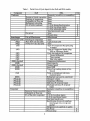
A Preliminary Assessment
of the ADUEPA Refrigerator/Freezer
Energy Simulation Model
K. J. Porter and C. W. Bullard
ACRCCR-02
For additional information:
Air Conditioning and Refrigeration Center
University of Illinois
Mechanical & Industrial Engineering Dept.
1206 West Green Street
Urbana, IL 61801
(217) 333-3115
September 1992
The Air Conditioning and Refrigeration
Center was founded in 1988 with a grant
from the estate of Richard W. Kritzer, the
founder of Peerless of America Inc. A State
of Illinois Technology Challenge Grant
helped build the laboratory facilities. The
ACRC receives continuing support from the
Richard W. Kritzer Endowment and the
National Science Foundation. Thefollowing
organizations have also become sponsors of
the Center.
Acustar Division of Chrysler
Allied-Signal, Inc.
Amana Refrigeration, Inc.
Bergstrom Manufacturing Co.
Caterpillar, Inc.
E. I. du Pont de Nemours & Co.
Electric Power Research Institute
Ford Motor Company
General Electric Company
Harrison Division of GM
ICI Americas, Inc.
Johnson Controls, Inc.
Modine Manufacturing Co.
Peerless of America, Inc.
Environmental Protection Agency
U. S. Army CERL
Whirlpool Corporation
For additional information:
Air Conditioning & Refrigeration Center
Mechanical & Industrial Engineering Dept.
University of Illinois
1206 West Green Street
Urbana IL 61801
2173333115
Introduction
The purposes of this report are 1) to describe the form and function of the ERA model, an EPA
Refrigerator Analysis program written by Arthur D. Little, Inc. (ADL, 1992), and 2) to identify
major differences between the ERA and its predecessor model developed by ADL for the U.S.
Department of Energy (ADL, 1982), hereafter referred to as the DoE model. The report is based
on the authors' experience using the DoE model for analyses of conventional top-mount
refrigerator/freezers, a reading of the ERA Users' manual (ADL, 1992), and attendance at a oneday workshop hosted by ADL.
ERA, like its predecessor, is a design model. That is, it cannot simulate off-design performance.
That is, it assumes implicitly that the capillary tube and refrigerant charge are re-optimized for
each operating condition specified by the user. It therefore cannot be expected to predict how a
given refrigerator/freezer will operate over a range of ambient temperatures, or over the range of
conditions experienced during cycling operation, or over a range of compressor speeds.
The following sections of this report provide a preliminary assessment of the model's user
interface, cabinet submodel, and cycle submodels. The depth of this assessment is necessarily
limited because it represents only a few staff-days effort. The concluding section of the report
identifies additional assumptions that require further evaluation or experimental validation.
Finally, suggestions are offered for manufacturers who wish to test the model's applicability to
actual refrigerators for which performance data are available.
User Input Interface
The DoE model's user input procedure is difficult and clumsy. The inputs to the model are read
from an input file FRIDGE.DAT created by the user. The file contains approximately 25
multiple item lines. The number of items on each line is dependent upon configuration to be
analyzed. For example, the number of cabinet dimensions is different for a chest freezer than a
top-mount refrigerator/freezer configuration. Therefore, the user must very well-schooled in the
necessary inputs when creating the input file. However, difficulties such as these were corrected
with the new program ERA.
ERA still uses an input file to supply data for analysis; however, the input files are created by the
program MENU. The first step when using the menu program is to read in a previously created
input file (various input files are provided with the software.) With this information stored, the
user can use the input menus to change some or all of the inputs. This is a very simple procedure
which is aided by well organized menus and the very extensive HELP utility. The information
requested by the menu system changes for each configuration. Therefore, the user knows that
only the information requested by the menu program must be supplied to describe a particular
configuration. The HELP utility is used to define ambiguous inputs. For example, the HELP
utility will tell the user how to measure the height of the particular configuration. Furthermore,
the HELP window changes with the user's position within the menu structure and can readily be
printed.
Cabinet Analysis
The cabinet analysis is conducted by the program CAB. The program CAB is run by the batch
file ERA. The input file for the program CAB is CAB.DAT which was created by the program
MENU. Described below are the inputs necessary for running CAB. Furthermore, the
similarities and differences between the DoE and ERA cabinet models are discussed.
Inputs
The majority of the inputs necessary to describe the cabinet have not changed from the DoE to
the ERA model. The user still must provide the cabinet dimensions, mullion dimensions,
1
insulation thicknesses, volumes, temperatures and thermal conductivities of the walls, wedge,
doors and mullion insulations. However, there have been changes in the following: compressor
compartment dimensions, gasket heat leaks, door openings, auxiliary energy use, auxiliary
thermal inputs and film coefficients. The compressor compartment dimensions are specified
using three dimensions in the ERA model while the DoE model only used two dimensions. In
the DoE model the user-specified the gasket heat leak for the freezer both with the fan off and
on, and the gasket heat leak for the fresh food compartment (BTU/HR-IN-F). However, for ERA
only one value is specified for the freezer gasket heat leak.
Unlike the DoE model, ERA considers the effects of door openings. For the ERA model the user
can specify the number of openings per hour and the duration of the opening for each
compartment door. The relative humidity is also a necessary input for the door opening model.
The input procedure for the auxiliary energy use has changed from the DoE model to the ERA
model. For the DoE model the user would specify amounts such as the steady-draw heat load
into the freezer, the heat into the fresh food compartment during the compressor off cycle, and
the gasket heat leak coefficients. For ERA the user can specify the freezer and fresh food gasket
heat leak coefficients and the anti-sweat heater electrical inputs. Then the user most specify what
fraction of these electrical inputs enters the freezer and fresh food compartments. The user can
also specify the freezer and fresh food internal moisture release and other heat sources.
The final difference between the DoE and ERA inputs for the cabinet model are the internal and
external film coefficients of the cabinet. For the DoE model they could be input by the user
while in the ERA model they have been hard-wired to 1.0 and 1.47 BTU/HR-FT2-DEG F,
respectively, in the routine QRDSET.FOR. The coefficients for the interior surface is therefore
assumed to be identical for the wire- and glass-shelved models.
Model
The general method used to calculate the thermal load on the cabinet has not changed much from
the DoE model to the ERA model. The load on the freezer is the sum of the 1-D heat transfer
through the walls and door, a wedge loss calculation to approximate 2-D effects at comers,
gasket heat leak and the mullion heat transfer. The load on the fresh food compartment is
calculated in a similar manner; however the mullion heat transfer is not included in the total
refrigerator cabinet load. Both models assume internal and external film coefficients are
identical for all surfaces and that both the room and the compartments are isothermal when
making these calculations. Furthermore, neither model consider the effects of radiation when
determining the thermal loads. However, the DoE model did consider the effect of the
evaporator fan on the gasket heat leak via an input parameter while the ERA model does not.
An addition to ERA over DoE is the routine DOORPN. DOORPN calculates the load associated
with the opening of both the freezer and fresh food doors. The user specifies the frequencies and
duration of the door openings for each compartment. The routine calculates both the latent and
sensible load associated with the initial tumbling of the air out of the compartment. It also
calculates the heat transfer associated with the sensible and latent loads that are assumed to
persist while the door is open. The heat and mass transfer coefficients used for these calculations
are hard-wired into the code. Therefore, these coefficients are considered independent of the
type of shelves in the refrigerator.
The cabinet model computer code is lengthy and sometimes difficult to decipher. Originally, we
believed that there was an error associated with calculation of the heat transfer of the mullion.
However, after consultation with the ADL, we realized that extraneous statements in the
computer code had misled us. More extraneous statements such as these could make a detailed
examination of the computer code very difficult.
2
Cycle Analysis
Inputs
Fewer input items are necessary for the DoE model compared to the ERA model. The cycle
inputs necessary for the DoE and ERA models are presented in Table 1. The X's in the fourth
column of Table 1 signify that the parameter can be calculated by ERA from a user-specified
refrigerant mass flow rate and other physical characteristics of the component.
More inputs are necessary for the ERA model due to the increased complexity of the model. For
instance, for the condenser of the DoE model, only one UA value is specified while for the ERA
model the conductances of the desuperheating, two-phase and subcooled region must be
specified. In order to simplify the determination of these inputs, ERA enables the user to
calculate these values from geometric parameters and the mass flow rate. The user must iterate
manually upon the final answer calculated by ERA because the mass flow rate used for the
calculation of the various conductances will probably not agree with the final calculated mass
flow rate. ADL states that this iteration process should take no more than two iterations
(Merriam, 1992).
3
Table 1. Partial List of Cycle Inputs for the DoE and ERA models
Component
Condenser
DoE
ERA
Cal.
Geometry (crossflow or counterflow)
Natural or forced convection Same
Entering air temperature
Same
Volumetric air flow rate
Same
Refrigerant subcoo1ing
Same
UA of entire condenser
U of the desuperheating region
X
U of the two-phase region
X
U of the subcoo1ed region
X
Total heat transfer area
X
Fan power
Same
X
Pressure drop
X
Interchanger
UA or Effectiveness
Effectiveness
Compressor (All) Entering air temperature
Same
(Map)
Mass flow rate data table
Capacity data table
(Map)
Power flow rate data table
Same
(All)
Type of Compressor (Reciprocating
or rotary)
(All)
Type of Compressor Model (Map,
EER or Efficiency Model
(All)
Cycle loss analysis for compressor
(All)
Control differential
(All)
Time constant
(All)
Shut valve option
(EER, physical)
Compressor displacement
(EER)
Rated capacity
(EER, physical)
Nominal speed
(EER)
RatedEER
(EER)
Type of can cooling (static or fanforced)
(All)
Temp. at compressor inlet (nonessential input)
(EER)
Refrigerant type used in calorimeter
(Physical)
Clearance volume
(Phy§ical)
Compressor efficiency
(Physical)
Shell loss (% of power input)
(Physical)
Discharge tube loss (% of power
input)
Evaporator
Geometry (crossflow or counterflow)
Natural or forced convection Same
Volumetric air flow rate
Same
UA of the entire evaporator U of the two-phase region
X
U of the superheated region
X
Total heat transfer area
X
Specification (Evap exit superheat,
interchanger exit, or evap exit
quality)
Refrigerant exit superheat or quality
Fan Power
X
Pressure drop
X
4
Table 1 also shows that ERA allows the user to specify various types of heat exchanger
geometries. A new control feature of the ERA model is the specification of the exit conditions of
either the evaporator or the suction line; the DoE model assumes the exit of the evaporator to be
saturated vapor. For ERA the user can specify the exit of the evaporator by supplying either the
evaporator exit quality or amount of superheat. When using the exit of the suction line as the
control option, the user must supply the amount of superheat. ERA also accepts the refrigerant
pressure drop across both the condenser and evaporator as an input while the DoE model
neglected pressure drop.
ERA requires the user to select one of three compressor models: map, EER or physically based
model, while the DoE model had only a compressor map model. Furthennore, the user can have
the ERA model calculate the loss associated with the cycling of the compressor. When
calculating the compressor cycling losses, the user must specify the control differential, cabinet
time constant and the existence of a shut off valve. The control differential is the dead band
associated with the cabinet temperature controller.
Sin~le Evaporator Model
The DoE cycle models are much simpler than the new cycle models of ERA. The DoE model
could handle both single and dual evaporator cycles; however, evaluation of the code was
difficult due to the lack of good documentation. ERA, on the other had, clearly states the type of
cycles which can be modeled. They are a single evaporator, a Lorenz cycle with a refrigerant
mixture, dual loop system with two separate loops, and dual evaporator cycle with two
evaporators in series. In the paragraphs below the different cycles of the DoE and ERA models
are described.
The DoE model utilizes two different types of condensers: forced and natural convection,
including a hot wall option. For the natural convection condenser, the heat transfer from the
condenser is calculated using the UA L\T. L\T represents the temperature difference between the
refrigerant condensing temperature and the air inlet to the condenser. For the forced convection
heat exchanger, the heat transfer is computed as the sum of the subcooled and two-phase heat
transfer. The subcooled heat transfer is calculated from a refrigerant-side energy balance. With
this infonnation the UA of the subcooled region can be detennined utilizing two assumptions.
First, the program assumes that the U value of the subcooled region equals the U value of the
two-phase region. Second, the algorithm assumes the heat capacity ratio of the refrigerant in the
subcooled region to the air passing over the region is negligibly small. Finally, the two-phase
heat transfer is calculated using a condensing effectiveness equation. The final value of the twophase heat transfer is reduced due to the presence of the subcooling region.
The four main differences between the DoE condenser model and the ERA condenser model are
the following.
1. The condenser is separated into three regions: de superheating, two-phase and
subcooled.
2. Each region has a user-specified (or calculated by ERA) conductance that is held
constant.
3. The user can not only select the mode of heat transfer, either natural or forced
convection, but the geometry of the heat exchanger, either crossflow or
counterflow.
4. The refrigerant pressure drop across the condenser is user-specified (or calculated
by ERA). The DoE model neglects pressure drop.
These differences make the ERA model more realistic than the DoE model.
5
The conductances and pressure drop of the condenser can either be specified by the user or
calculated by ERA from the mass flow rate of the system and the physical characteristics of the
condenser. The programs ERACOND and ERAEVAP are used to make these calculations for
the condenser and evaporator, respectively. These programs use standard correlations for
determining the heat transfer coefficients and pressure drop. When making these calculations,
the program makes assumptions about certain physical processes and applies them to all
refrigerator configurations. For example, the volumetric air flow rate specified by the user is
converted to an air velocity which is then used to determine the Reynolds number for the air.
Therefore, if possible the user should use experimentally derived conductances.
The interchanger for both the DoE and ERA models is assumed to be a simple counterflow heat
exchanger with liquid in one line and vapor in the other line. Utilizing the user-specified
effectiveness, the heat transfer of the interchanger can be determined. By knowing the
evaporating temperature, the inlet temperature to the compressor can be determined.
DoE compressor model is quite simple. Both the mass flow rate and power consumption of the
compressor are calculated using calorimeter map data. The program interpolates to determine
mass flow rate as a function of both the condensing and evaporating temperatures. The heat
transfer from the compressor is calculated using a UA L\T equation. The UA value is hard-wired
into the code at 4.39 BTU/hr F and the L\T is the difference between the refrigerant compressor
exit temperature and the air temperature over the compressor which was specified by the user.
Unlike the DoE model, the new ERA compressor model is enhanced with many new options.
The compressor can be modeled in one of three different ways. The same compressor map
model (based on power and capacity calorimeter data) is corrected for non-standard suction inlet
temperatures. The corrections for mass flow rate and compressor power are correlations,
determined by ADL, based on experimental data. The EER compressor model utilizes isentropic
and volumetric efficiencies to calculate the mass flow rate and compressor power. These
efficiencies are calculated from the data provided by the user for a particular rating point.
Furthermore, the suction port inlet temperature and the discharge temperature are calculated as
functions of the EER. The third compressor model is physically based and utilizes isentropic and
volumetric efficiencies to determine the mass flow rate and compressor power. The compressor
heat loss for the map model is a fraction of the input compressor power. This fraction is 0.75
times a temperature ratio. The method used to determine the EER model's heat loss could not be
determined. The heat loss of the physically based model is similar to the compressor map
method except that the fraction 0.75 can be changed by the user.
The ERA model also allows an optional calculation of cycling losses. The first step of this
submodel is to determine the cycling rate of the compressor as a function of the compressor duty
cycle, the control differential and the cabinet time constant. The cycling loss is then calculated
from a correlation based upon experimental data. However, the data used to determine this
correlation was obtained from compressors having COP's of 0.5 - 0.6 (Janssen, et al, 1990).
Both the DoE and ERA evaporator models begin by calculating the inlet air temperature of the
evaporator. Both models calculate this air temperature by considering the mixing of the air from
the fresh food and freezer compartments. The algorithm used by the DoE model is not
documented and nearly-impossible to decipher from the source code. The ERA routine for
calculating the inlet evaporator temperature is similar but still difficult to follow. With the inlet
air temperature to the evaporator calculated, the DoE model can simulate three different types of
evaporators. The first choice is to determine the heat transfer using UA L\T, where the UA is
specified by the user and the L\T represents the temperature difference between inlet air
temperature and the refrigerant evaporating temperature. Second, the effectiveness of the forcedconvection evaporator is calculated using the user-specified UA and volumetric air flow rate.
The heat transfer can then be determined from a effectiveness heat transfer equation. Finally, a
natural convection evaporator can be modeled. The effective heat transfer coefficient is
calculated from the sum of convection and radiative heat transfer coefficients. The convection
6
coefficient is equal to 1/4 times the fourth root of the temperature difference. The ERA models
the natural and forced convection, crossflow and counterflow evaporators in a manner similar to
the DoE model. The main difference is the user-specified refrigerant exit condition rather than
the saturated vapor exit condition of the DoE model. At the user's option, the ERA evaporator is
considered to consist of both a two-phase and superheated regions with each section having its
own user-specified conductance.
Solution Techniqye
The overall solution technique is identical for both models. They both assume initial condensing
and evaporation temperatures. They then proceed to iterate on the evaporating temperature until
the evaporator energy balance is achieved. The program iterates until the guessed condensing
temperature equals the calculated temperature. The main difference between the models'
solution techniques is the forced-answer capability of the ERA program. The user can force the
program to stop iterating by pressing a key during the iteration process. This enables the user to
acquire some results when the program will not converge upon a solution.
DuallOQP. Lorenz and dual evaporator cycles .
The dual loop model contains two separate refrigerant cycles. Each cycle acts independently to
achieve the average temperature for each compartment as specified by the user. For the Lorenz
and dual evaporator cycles, the air temperatures entering the evaporators are the user-specified
compartment temperatures. Normally, the evaporator loads will be unbalanced. The user must
specify one of five control options to correct this.
The difference between the Lorenz and the dual evaporator cycles is the type of refrigerants used.
The Lorenz cycle uses a refrigerant mixture while the dual evaporator cycle normally uses a pure
refrigerant. In either case, the evaporators and condenser are modeled in a similar manner. For
the dual evaporator case, the specific heat of the two-phase region is considered infinite and
therefore the refrigerant temperature remains constant in this region. However, for Lorenz cycle,
a temperature glide is achieved in the two-phase region due to the fact that the specific heat of
the refrigerant mixture is not infinite. The specific heat is calculated as the ratio of the enthalpy
difference to the temperature difference across the region.
The programs ERACOND and ERAEVAP should not be used to calculate the U's for NARM's;
the U's should be specified by the user.
Conclusions, cautions and suggestions
The user interface program of ERA is very useful and well done. Furthermore, the user manual
is well organized and does good job of detailing all the algorithms used within the computer code
to conduct the analysis. However, it would be useful for beginning PC users if the following
interface features were built into ERA.
•
Provided a file view program which could be used to view the results of the
program.
•
In the user manual, show how the user can edit the ERA batch file so that the
results could automatically be viewed using the screen program provided.
•
Set up the program so that it does not have to be restarted after each calculation
run.
The cabinet model accounts for all major heat loads into the cabinet, however with varying
degrees of sophistication. For example, the wedge loss is model rigorously modeled using a
coordinate transformation while the gasket heat leak is calculated from a single user-specified
coefficient. The analytical basis for simplistic calculations such as the gasket heat leak is not
well-justified. Listed below are a few suggestions for improvement in the cabinet model.
7
•
Allow different internal and external film coefficients for the walls of both
compartments. In the ERA model, these coefficients are hard wired into the code
while for the DoE model, they were inputted by the user. Therefore, these
coefficients are not a function of either fan speed or interior refrigerator geometry
(e.g. wire and glass shelving).
•
Create the option of having different internal temperatures associated with each
wall of the compartments.
•
Model radiative heat transfer for cabinet walls and for door openings.
•
Model the gasket heat leak in a more sophisticated manner rather than a user
supplied coefficient. A detailed sub-model might be useful for evaluation of
different gasket designs. Furthermore, the model should consider the effect of fan
speed on the internal film coefficient and on gasket infiltration Presently, the
coefficients used do not consider the effect of the evaporator fan on the heat leak.
The DoE model had a separate coefficient for the freezer gasket heat leak when the
evaporator fan was on.
•
The calculations used to determine the heat loss due to door openings seem
limited. They are based on hard-wired coefficients which can not account for the
various differences in interior refrigerator geometry.
In general, the cycle model of ERA is much improved over the DoE model. The ERA model
explicitly allows the user to choose one of four different cycles and the condenser and
evaporators are modeled in a more realistic manner. Listed below are questions and cautions
about ERA's cycle models.
•
There are assumptions hidden within the calculations of the heat transfer
coefficients by the programs ERACOND and ERAEVAP. For instance,
undocumented assumptions about the geometry of the heat exchanger underlie
calculations of the air velocity from the user-specified volumetric air flow rate.
•
User-specified conductances (for superheated, two-phase, and subcooled zones)
are independent of refrigerant mass flow rate.
•
There are many correlations used in both the EER and physically based
compressor models. Since these correlations are not documented in the code, how
can the user feel comfortable in using them? Furthermore, how can the user be
sure that they are not being used outside of their range of applicability?
•
Both the EER and the physically-based model allows the user to change the
compressor speed; however, this does not allow the user to adequately model a
variable speed compressor. During the operation of a variable speed compressor,
the amount of sub cooling of the condenser and the superheat of the evaporator
will change. This effect is not simulated by the ERA model.
•
A run of the ERA program produced a negative clearance volume and a
volumetric efficiency greater than one. Neither of these two obvious errors where
flagged by the program.
•
Is it possible that the program is too user-friendly? One of the features of the
program is to model the increased efficiency associated with reductions in the
compressor speed. This process is documented near the end of Appendix B of the
ERA User's manual. In this section, it states that ERA cannot account for the loss
of motor efficiency associated with lower speeds. It assumes that the user will
8
adjust the EER value appropriately; however, will the average user make this
adjustment?
•
Are different input parameters independent of each other? The user must
remember that the heat transfer coefficients previously calculated must be
changed if the cycle refrigerant or air flow rate is changed.
•
The model used to calculate the cycle loss seems to be based on very little data.
Furthermore, the compressors used for these calculations had a COP in the 0.5 0.6 region. Should these correlations be used for compressors with much higher
COP's?
Specific research projects could be designed to test specific assumptions such as those identified
above. In addition, manufacturers interested in evaluating the model's applicability might
consider the following types of investigations, which would rely on unpublished data:
•
Compare actual reverse heat leak test results with values calculated from cabinet
dimensions and other data available for existing and prototype RIF's. The
resulting scatter plot would reveal any bias and uncertainty present in the model
results.
•
Compare standard energy use results to model predictions, as above.
Comparability will be limited, however, because some of the required inputs to
the cycle model are themselves subject to great uncertainty (e.g. conductances for
heat exchanger zones).
•
Compare calculated VA's for evaporator and condenser to those obtained from
calorimeter tests.
Perhaps the results of some of these analyses could be released via AHAM without revealing
proprietary information.
The available documentation does not make a convincing case that ERA can be used to predict
energy savings resulting from the cumulative effect of successive energy efficient improvements.
ERA seems to have this capability, if the model is used in a proper manner with realistic input
parameters; however, it can easily be corrupted. For example, if the initial gasket heat leak
coefficients specified are twice the actual values, an incorrect energy savings will be achieve
when the gasket heat leak coefficients are assumed to cut in half. Moreover, ERA can yield
dangerous results if the user selects several different energy efficiency improvements which can
not be implemented together in a real refrigerator (e.g. superinsulation and a high EER
compressor with no change in cycling losses).
References
Arthur D. Little, Inc., Refrigerator and Freezer Computer Model User's Guide, V.S. Department
of Energy, Washington D.C., 1982.
Arthur D. Little, Inc., EPA Refrigerator Analysis Program User's Manual Peer Review Draft,
1992.
M.J.P. Janssen, J.A. deWit, and L.J.M. Kuijpers, "Cycling Losses in Domestic Appliances: An
Experimental and Theoretical Analysis," Proceedings of the 1990 USNC/IIR - Purdue
Refrigeration Conference, pp. 90 -98, July, 1990.
Richard Merriam, communication at ERA Workshop, College Park Maryland, July 21, 1992.
9