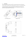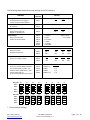
1
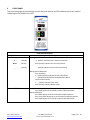
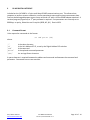
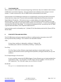
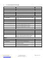
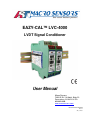
EAZY-CAL™ LVC-4000
LVDT Signal Conditioner
User Manual
Macro Sensors
7300 US Rt. 130 North, Bldg. 22.
Pennsauken, NJ 08110 U.S.A.
856.662.8000
www.macrosensors.com
Manual P/N 0653 0006 0000
Rev. E
July 3, 2013
AST / Macro Sensors
www.macrosensors.com
LVC-4000 User Manual
Manual P/N 0653 0006 0000 Rev. E
Page 2 of 14
TABLE of CONTENTS
1
GENERAL DESCRIPTION ................................................................................................................ 4
2
ELECTRICAL CONNECTIONS ........................................................................................................... 5
3
FRONT PANEL ............................................................................................................................... 8
4
DIP SWITCHES .............................................................................................................................. 6
5
CALIBRATION PROCEDURE ........................................................................................................... 9
5.1
6
Notes on Calibration .............................................................................................................. 9
RS-485 DIGITAL INTERFACE ......................................................................................................... 10
6.1
Command Format................................................................................................................ 10
6.2
Commands .......................................................................................................................... 11
7
SYNCHRONIZATION .................................................................................................................... 12
8
ERROR DETECTION AND INDICATION .......................................................................................... 12
9
GENERAL SPECIFICATIONS .......................................................................................................... 13
AST / Macro Sensors
www.macrosensors.com
LVC-4000 User Manual
Manual P/N 0653 0006 0000 Rev. E
Page 3 of 14
1
GENERAL DESCRIPTION
The EAZY-CAL™ LVC-4000 is a standalone signal conditioner, supporting a wide range of LVDTs, RVDTs
and Half-Bridges and providing several choices of voltage, current, and digital RS-485 outputs. Push
button calibration offers intuitive operation as compared to units with span and offset trim pots. Fault
conditions such as a wire break on LVDT connections are indicated by blinking LEDs, output of an error
voltage or current, and Error Flag Open Collector signal. The LVC-4000 operates from a 9 – 30VDC
power supply and is housed in a polyamide DIN rail-mounted enclosure. Calibration instructions,
terminal functions, LVDT connection diagram and DIP switch functions are printed on the side panels for
convenience.
Synchronization to other signal conditioners is accomplished by a daisy chain connection to a
synchronization bus. One unit will assume the Master function based on DIP switch priority setting. If a
fault should occur, the next highest priority unit will take over as Master.
With the use of the RS-485 port, a host computer is able to retrieve measurement data, receive
operational status, perform remote calibration and perform hot swap reconfiguration.
Hot swap is further simplified by the pluggable terminal block feature. An LVC-4000 can be quickly
replaced in a live system without the need to unscrew terminal connections or sever connections
between other signal conditioners.
The following sections describe the features and operation of the LVC-4000.
AST / Macro Sensors
www.macrosensors.com
LVC-4000 User Manual
Manual P/N 0653 0006 0000 Rev. E
Page 4 of 14
2
ELECTRICAL CONNECTIONS
There are four color coded terminal plugs, each having 4 screw terminals. The 16 terminals are labeled 1
through 16. Terminal plugs can be easily plugged and unplugged to facilitate LVC-4000 replacement in
system. The terminal names and their function shown below:
Color
White
Red
Blue
Black
Terminal
1
2
3
4
5
6
7
8
9
10
11
12
13
14
15
16
Name
SYNC I/O
ERROR FLAG
PRI-1
PRI-2
SHIELD (GND)
SEC_CT
SEC-1
SEC-2
VDC OUT
n.c.
GND
IDC OUT
RS-485 B
RS-485 A
-VIN (GND)
+VIN
LVDT/LVRT Connection Diagram
Function
Synchronization Master/Slave Input/Output
Error Flag Output
Primary Excitation to LVDT
Primary Excitation to LVDT
Optional cable Shield connection
Optional Secondary CT conn. (n.c.)
Secondary signal from LVDT
Secondary signal from LVDT
Output Voltage
No Connection
VOUT / IOUT Return
Output Current
RS-485 Data +
RS-485 Data Supply Voltage Return
Supply Voltage In
Half-Bridge Connection Diagram
Note – select either voltage (factory default) or current output using DIP SW1.
AST / Macro Sensors
www.macrosensors.com
LVC-4000 User Manual
Manual P/N 0653 0006 0000 Rev. E
Page 5 of 14
3
DIP SWITCHES
There are two 8-section DIP switches on the PCB. The switches provide selection of Primary Level,
Excitation Frequency, Bandwidth, Output Voltage Range Select, Output Invert, and RS-485 Bus Address.
To access the DIP switches, the front cover and PCB must be withdrawn from the housing. Use a
screwdriver or similar tool to depress the top latch. The cover will spring forward. Repeat with the
bottom latch, then gently pull the PCB out, as shown:
AST / Macro Sensors
www.macrosensors.com
LVC-4000 User Manual
Manual P/N 0653 0006 0000 Rev. E
Page 6 of 14
The following table shows the control settings of the DIP switches:
SWITCH SECTION
FUNCTION
SETTING
Primary Drive
Select between 3Vrms (High) &
1.5Vrms (Low) Excitation Output
Reserved
No Function
Output Invert
SW1-1
High
OFF
ON *
Normal
Invert
OFF *
ON
SW1-2
Reverse the direction of
Output vs. displacement
SW1-3
Output Range
Select one of five VDC
outputs or the IDC output.
SW1-4
SW1-5
SW1-6
SW1-7
SW1-8
All Off:
Frequency
Select one of four
Excitation Frequencies
Filter
Select one of 4 filter cutoffs
Bus Address
Select one of 16 RS-485 Bus Address
via a 4 switch binary number. See
table for switch combinations. (Also
used to select order of
Synchronization Master/Slave order.)
BUS ADDR: 00 *
Low
0-10VDC *
0-5VDC
0.5-4.5VDC
+/-5VDC
'+/-10VDC
4-20 mADC
(Only 1 switch
on at a time)
2.5KHz
5KHz
7.5Khz
10KHz
SW2-1
SW2-2
OFF *
OFF *
ON
OFF
OFF
ON
ON
ON
SW2-3
SW2-4
1Hz
OFF
OFF
10Hz
ON
OFF
100Hz
OFF
ON
none
ON *
ON *
ON / OFF:
SW2-5
SW2-6
SW2-7
SW2-8
ADDR0 (lsb)
ADDR1
ADDR2
ADDR3 (msb)
1/0
1/0
1/0
1/0
01
02
03
04
05
06
07
OFF
ON
OFF
ON
OFF
ON
SW2-5:
OFF
ON
SW2-6:
OFF
OFF
ON
ON
OFF
OFF
ON
ON
SW2-7:
OFF
OFF
OFF
OFF
ON
ON
ON
ON
SW2-8:
OFF
OFF
OFF
OFF
OFF
OFF
OFF
OFF
BUS ADDR:
08
09
10
11
12
13
14
15
SW2-5:
OFF
ON
OFF
ON
OFF
ON
OFF
ON
SW2-6:
OFF
OFF
ON
ON
OFF
OFF
ON
ON
SW2-7:
OFF
OFF
OFF
OFF
ON
ON
ON
ON
SW2-8:
ON
ON
ON
ON
ON
ON
ON
ON
* - Factory default settings.
.
AST / Macro Sensors
www.macrosensors.com
LVC-4000 User Manual
Manual P/N 0653 0006 0000 Rev. E
Page 7 of 14
4
FRONT PANEL
The front-facing side of the enclosure contains the push buttons and LED indicators which are used for
calibrating the LVC-4000 to the LVDT.
OPER / CAL LED
POSITION LEDs:
(Red)
Front Panel Description
On indicates Operating Mode, Blinking indicates Calibration Mode.
During Calibration:
‘+’ (Yellow) indicates core is above null position
+
(Yellow)
NULL
(Green)
NULL (Green) indicates core is at null position
-
(Yellow)
‘-’ (Yellow) indicates core is below null position
During Normal Operation:
Error Condition:
‘+’ (Yellow) blinking indicates Primary Wire Break
‘-’ (Yellow) blinking indicates Secondary Wire Break
Synchronization State:
‘+’ (Yellow) indicates Slave mode
NULL (Green) indicates Master mode
FULL SCALE / ZERO Buttons:
AST / Macro Sensors
www.macrosensors.com
During Normal Operation:
Press both buttons for 3 seconds to enter Calibration Mode
During Calibration:
Press ZERO button to set core minimum endpoint position
Press FULL SCALE button to set core maximum endpoint position
Press both buttons for 3 seconds to abort Calibration Mode
LVC-4000 User Manual
Manual P/N 0653 0006 0000 Rev. E
Page 8 of 14
5
CALIBRATION PROCEDURE
Calibrating the LVC-4000 consists of entering Calibration Mode, finding the NULL (center) position of the
LVDT, attaching the core to the object to be measured, and then moving the core to set the ZERO and
FULL SCALE positions that will correspond to the minimum and maximum output voltage or current. The
LVC-4000 returns to Operating Mode immediately after both positions have been set.
The basic calibration instructions are printed on the side of the LVC-4000 for reference.
Directions are as follows:
1. Set the LVC-4000 DIP Switches for the desired application. The factory default settings provide a
0 – 10VDC output, and are typical for most standard LVDTs. Refer to section 3.0 for details.
2. Connect the LVDT to the LVC-4000 as shown in the connection diagram and apply power. The
OPER/CAL LED will light, along with the Green NULL LED (if the unit is in Master Sync mode), or the
Yellow + LED (if the unit is in Slave mode). (3 minutes of warm-up time is recommended.)
3. Enter the Calibration Mode by pressing and holding both buttons simultaneously for 3 seconds
minimum. The OPER/CAL LED will begin blinking.
4. Move the LVDT core to NULL position by observing the 3 Position LEDs. The + and – LEDs indicate
that the core is inserted or extended beyond the NULL, respectively.
5. Attach the core to the workpiece to be measured so that the workpiece center of motion is aligned
with the LVDT NULL.
6. Move workpiece to its minimum position and press the ZERO button. Wait for the Position LEDs to
stop blinking.
7. Move workpiece to its maximum position and press the FULL SCALE button. The unit will exit
Calibration Mode and operate with its new calibration. The OPER/CAL LED will be steady On.
5.1
•
•
•
•
•
•
Notes on Calibration
It is important that the NULL position be set as close as possible to the center of the displacement
range. Otherwise, non-linearity errors may result at or near the endpoint positions.
The LVDT core MUST NOT protrude from the LVDT during the calibration, or erroneous calibration
will result.
Calibration may be performed by setting the FULL SCALE position first rather than ZERO position.
Either end position may be on either side of NULL.
Any portion of the LVDT specified displacement can be calibrated to produce a full output span. If
the desired displacement is asymmetrical, set the endpoint that is farthest from NULL first.
Swapping SEC-1 with SEC-2 or PRI-1 with PRI-2 LVDT connections will reverse the direction indicated
by the Position LEDs.
Calibration mode can be canceled by pressing the 2 buttons simultaneously for 3 seconds.
AST / Macro Sensors
www.macrosensors.com
LVC-4000 User Manual
Manual P/N 0653 0006 0000 Rev. E
Page 9 of 14
6
RS-485 DIGITAL INTERFACE
Included on the LVC-4000 is a 2 wire multi-drop RS-485 communications port. This allows a host
computer to perform remote calibration, receive operational status and retrieve measurement data.
Data can be exchanged between one or more units and a PC with a USB-to-RS485 adapter attached. A
terminal program (Hyperlink) or 3rd party software is required. Port parameters are currently set to
9600 bps, no parity, 8 data bits and 1 stop bit (9600, NP, 8,1). Data is ASCII.
6.1
Command Format
Units respond to commands in the format:
:aa cmd param (CR)
where:
‘:’
‘aa’
‘cmd’
‘param’
‘(CR) ‘
is the colon character,
is the Unit Address 00..15, as set by the Digital Address DIP switches
is the command
is the optional command parameter
is a carriage Return character
A space character is required between the address and command and between the command and
parameter. Commands are not case sensitive.
AST / Macro Sensors
www.macrosensors.com
LVC-4000 User Manual
Manual P/N 0653 0006 0000 Rev. E
Page 10 of 14
6.2
Commands
The currently implemented commands and their descriptions are as follows:
getConfig - Shows the operating state of the unit and displays a list of all of the significant
parameters, as shown in the example below:
Macro Sensors LVC-4000 Configuration:
H/W Version
REV. -F/W Version
0.7
Serial No.
Bus Address
0
Excitation Freq.
2.5KHz
Filter Select
NONE
Invert
NORM
Output Range
VOUT U10
ADC Slope
4.048681
ADC Offset
301
INA Gain
2
ADC Range
1
Sync State
MASTER
Note that the ADC Slope, ADC Offset, INA (Instrumentation Amplifier) Gain, and ADC Range parameters
are computed during calibration, and can be downloaded into another unit. This allows for hot swap
configuration, where a replacement unit can instantly function in place of the old unit without the need
for rerunning the calibration process.
getOut
Returns nominal analog output value scaled in units that depend on the setting of the
Output Range DIP switches.
sADCsl
Set the ADC Slope coefficient during hot swap reconfiguration.
sADCos
Set the ADC Offset coefficient during hot swap reconfiguration.
cal
Enter Calibration Mode
getLEDs
Get state of LEDs during calibration.
setFull
Set the Full displacement position during calibration.
setZero
Set the Zero displacement position during calibration.
setINA
Set the Instrumentation Amplifier gain during hot swap reconfiguration.
abortCal
Terminate the calibration procedure and go to Operate Mode. The LVC-4000 uses
parameters which were in place before the start of the calibration.
getError
returns the error status.
help
Lists all the available LVC-4000 commands.
AST / Macro Sensors
www.macrosensors.com
LVC-4000 User Manual
Manual P/N 0653 0006 0000 Rev. E
Page 11 of 14
7
SYNCHRONIZATION
When multiple LVC-4000s share interconnecting wiring, interference may occur between them because
of differences in excitation frequency. This may produce noise oscillations on the voltage or current
outputs. In order to prevent this, the LVC-4000s can be synchronized with each other.
Synchronization of LVC-4000 signal conditioners is accomplished by connecting the SYNC I/O terminals
of each unit into a daisy chain. One unit will assume Master Mode based on the priority set by the
Digital Address DIP switches. With each unit set to a unique address, the lowest addressed unit
becomes Master. All other units enter Slave Mode. If the current Master ceases to function, the next
consecutively-addressed unit enters Master Mode without user intervention. If a unit is hot swapped or
reconnected, it will enter Slave Mode. In an interconnected group of units, one and only one LVC-4000
is guaranteed to be Master, even if duplicate addresses exist.
Synchronization mode is indicated by the ‘+’ (Yellow) LED for Slave Mode, and the NULL (Green) LED for
Master Mode.
8
ERROR DETECTION AND INDICATION
The LVC-4000 detects and reports operational failures, including broken connections to the LVDT
Primary and Secondary windings. Error conditions are indicated as follows:
LEDs:
Primary Open condition is indicated by a blinking ‘+’ (Yellow) LED.
Secondary Open condition is indicated by a blinking ‘-’ (Yellow) LED
Error Flag:
The Error Flag is an Open Collector output signal requiring an external pullup resistor. The
output is low (transistor turned on) during normal operation, and high (turned off) for any error
condition.
Error Output Voltage or Current Level:
An error condition causes the LVC-4000 Voltage or Current Output to go to a level outside of the
measurement range. For 0-10 VDC or 0-5 VDC ranges, the error voltage is -0.5 VDC and -0.25
VDC respectively. For 4-20 mADC range, the error current is 0 mADC.
RS-485 Bus:
The getError command returns the error status.
AST / Macro Sensors
www.macrosensors.com
LVC-4000 User Manual
Manual P/N 0653 0006 0000 Rev. E
Page 12 of 14
9
LVC-4000 GENERAL SPECIFICATIONS
Parameter
Power:
Input Voltage
Excitation:
Primary Voltage (nominal)
Primary Current
Primary Impedance
Primary Frequency
Signal Output:
Voltage Output
Current Output
Loop resistance
Frequency Response
Low Pass Filter
Output Voltage Ripple
Output Current Ripple
Output Non-Linearity
Environmental:
Temp. Co. Gain
Temp. Co. Offset
Operating Temperature Range
Enclosure
EMC Compliance
Features:
Synchronization Capability
Automatic Calibration
Null Detection
Digital interface
Error Detection
Error Flag
AST / Macro Sensors
www.macrosensors.com
Value
Comment
9-30 VDC, 90 mA max @ 24 VDC
3 Vrms (1.5 Vrms selectable)
30 mA max
90Ω min ( @ 1.5 Vrms)
2.5 kHz, 5 kHz, 7.5 KHz or 10 kHz
0-10 VDC, 0-5 VDC, 0.5-4.5 VDC, ±5 VDC, or ±10 VDC,
selectable
4 - 20 mADC
1KΩ max. with 24 V DC supply
500Hz Max
1Hz, 10Hz, 100Hz or none, selectable
1 mV rms max (2.5KHz Excitation, no Filter)
2 mV rms max (10KHz Excitation, no Filter)
10 µA rms max (2.5KHz Excitation, no Filter)
20 µA rms max (10KHz Excitation, no Filter)
< ±0.1% of FSO
<0.02% FRO/°C
<0.02% FRO/°C
-20°C to 75°C
4.5 x 3.9 x .9 in., Green
Emissions: EN55011:2007
Immunity: EN61000-4-2:2009, EN61000-4-4:2004,
EN61000-4-6:2009, EN61000-4-3:2010+A2:2010
Master/Slave Synchronization via single wire bus.
Via Front Panel Push Button or RS-485 command
Via Front Panel LEDs or RS-485 command
RS-485 2-wire multi-drop network,
16 addresses selectable
Primary or Secondary Wire Break Detect, indicated by
LED, Error Flag, and Error Output Level
Open collector output, 50 mA, 30 V DC max.
LVC-4000 User Manual
Manual P/N 0653 0006 0000 Rev. E
Page 13 of 14
AST / Macro Sensors
www.macrosensors.com
LVC-4000 User Manual
Manual P/N 0653 0006 0000 Rev. E
Page 14 of 14