1
TXT PRO´09
GAS GAS thank you for the trust you have
placed in us.
By choosing the new GAS GAS TXT Pro 2009 you have
become part of the great GAS GAS family and, as a user
of the number one manufacturer of off-road motorbike,
you deserve the distinguished treatment that we wish to
offer to you both in our after-sale relationship and in the
explanations that we provide in this manual.
Our Pro 2009 is a bike conceived for the practice of highcompetition trial. It is actually the fruit of many years of
competition and experimentation in this demanding
discipline, as well as the many great successes achieved
thanks to great trial riders who have contributed with their
expertise to the basic data that have allowed us to create
a high-level motorbike, a GAS GAS which counts on its
low weight as a significant key factor.
Congratulations for making the right choice. With your skills
at the commands of this motorbike, an adequate preparation
and the indispensable servicing for this to be highly reliable,
you will be able to enjoy the most comfortable and rewarding
trial practice.
Thank you for your trust in us, and welcome to GAS GAS
Motorbikes.
GAS GAS MOTOS, S.A.
August - 2008
-3-
Important notice
Read this Manual carefully. You will find it contains all the necessary information for your safety, and
that of third persons, as well as guaranteeing the correct conservation and maintenance of the GAS
GAS motorbike you have just bought.
You will find all the necessary instructions for the correct riding and control of this vehicle are set out
below. Each message is proceeded by a sign whose meaning is the following:
Be careful! This sign introduces all those rules and precautionary measures necessary to
avoid slight or severe injuries, or even the death of the user should these instructions not be
correctly followed.
Look out! This sign introduces special warnings to avoid damaging your motorbike. Should
these warnings not be heeded, the guarantee may be automatically invalidated.
Various notes. These are the indications necessary for the optimal control and adjustment
operations, together with those tasks of conservation and maintenance of the motorbike in
order that you may obtain the greatest possible satisfaction from your vehicle.
The aim of this Manual is to help the user to minimise or avoid possible damage to people, property,
the environment, and naturally to his/her new motorbike. For this reason, all the information presented
here is based on data obtained from the latest models put on the market just before the publication
of this Manual. However, GAS GAS Motos, S.A. reserves the right to make modifications without any
prior warning being given to consumers and without incurring any additional obligations in so doing.
Your local dealer will also provide you with any information as might be deemed necessary.
-4-
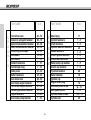
Contents
Thanks to consumer
Important notice
Warranty regulations
Recommendations
Technical specifications
Component location
Maintenance guide
Serial number
Combination switch
Steering lock
Combustible
Fuel tank cap
Fuel tap
Starter
Carburation
Kick-start engine pedal position
Lever regulation
Oil level checking
Crankcase fill-in
Crankcase draining
Air filter box cleaning
Fuel tank dismantle
Radiator fill-in
Spark dismantle
Spark check
Air filter box dismantle
3
4
6 to 8
9
10 & 11
12 & 13
14 & 15
16
17
18
18
19
20
20
20
21
21
22
22
22
23
24
24
25
25
26
Carburettor dismantle
Carburettor capacity check
Carburettor cleaning
Inlet valves dismantle
Inlet valves
Clutch operations
Discs and clutch spring
Air bleed
Water pump draining
Front suspension
Rear suspension
Swing-arm articulations
Articulation lubrication
Chain fixing link position
Chain and wheel tension
Tyres and tyre pression
Brakes
Rear brake fluid tank
Torques
Storage
Multifunction
Troubleshooting
Finally recommendations
Homologation
-5-
27
27
27
28
28
29
29
29
29
30 & 31
31
32
33 to 35
36
36
37
38
39
40
41
42 to 49
50
55
56 & 57
WARRANTY TERMS AND CONDITIONS
(According to Law decree 23/2003 on the 10th of July, covering Warranties on Consumer Item Sales)
Warranty terms of the manufacturer GASGAS Motos, S.A.
The company GAS GAS MOTOS, S.A. (hereafter referred to as “GG”), with this present document guarantees the consumer,
the purchaser of a vehicle manufactured by GG, that both the materials and the manufacturing are free of defects in
accordance with the highest standards of quality. Consequently, GG with this document guarantees the consumer (hereafter
referred to as the “purchaser”), in accordance with the conditions set out below, the repair, free of charge, of any defect
in materials or that might result from faulty manufacture that is detected in a new motorcycle within the period covered by
this Warranty and with no limit on the number of kilometres covered or hours of use.
Warranty Period
The period covered by this Warranty will begin on the day of delivery of the vehicle to the purchaser by a GG authorised
dealer, or in the case of demonstration models, on the date in which the vehicle is used for the first time.
The seller will be responsible for any unwarranted faults that become apparent within the period established in the Law
decree 23/2003 on the 10th of July covering Warranties on Consumer Goods Sold from the time of delivery and in accordance
with the Directive 1999/44/EC for other members of the European Community. For countries outside the European
Community, the Warranty Period will be determined by the existing regulations in those countries. Nevertheless, should
the fault appear during the first six months after the delivery of the motorcycle, it will be presumed that the said fault existed
at the time of delivery; from the end of the sixth month onwards, the purchaser must demonstrate that the unwarranted
fault existed at the moment of delivery. During the first six months subsequent to the delivery of the repaired vehicle, the
seller will be responsible for any unwarranted faults arising out of the repair.
Any defects detected in the product must be brought to the attention of a GG authorised dealer within the Warranty Period.
If the last day of this period is a Sunday or an official holiday, the Warranty period will be extended such that the last day
of the period covered will be the first working day after the Sunday or official holiday.
Those claims under Warranty for defects not brought to the attention of a GG authorised dealer before the end
of the Warranty Period will be excluded.
-6-
Obligation of the purchaser
GG will have the right to reject any claims under Warranty in the event that:
a) The purchaser has failed to submit the vehicle to any of the inspections and/or maintenance work required in the Users’
Manual, or has exceeded the date set for such inspections or maintenance work. Also excluded from guarantee are those
faults that appeared prior to the dates established for an inspection or maintenance work where the latter was not carried
out, or was carried out later than the date established.
b) An inspection, maintenance or repair has been performed on the vehicle by third parties not recognised or authorised
by GG.
c) Any maintenance or repair has been carried out on the vehicle that violates the technical requirements, specifications
and/or instructions indicated by the manufacturer.
d) Spare parts whose use has not been authorised by GG have been used during the course of maintenance work or repairs
to the vehicle, or in the event that the vehicle has been used with fuels, lubricants or other liquids (including, amongst others,
cleaning products) that have not been expressly mentioned in the specifications set out in the User’s Manual.
e) The vehicle has been altered or modified in any way or fitted with components other than those expressly authorised
by GG as accepted components of the vehicle.
f) The vehicle has been stored or transported in a way that is not in accordance to the corresponding technical requirements.
g) The vehicle has been used for special purposes other than ordinary use, such as competition, races or record breaking
attempts.
h) The vehicle has been directly or indirectly damaged as a result of a fall or an accident.
Warranty exclusions
The following items are not covered by this Warranty:
a) Worn parts, including, without any limitation, spark plugs, batteries, petrol filters, oil filter elements, (secondary) chains,
engine output pinions, rear sprockets, air filters, brake discs, brake pads, clutch plates and discs, bulbs, fuses, carbon
brushes, footrest rubbers, tyres, inner tubes, cables and other rubber components
b) Lubricants (for example, oil, grease, etc.) and working fluids (for example, battery liquid, coolant, etc.)
c) Inspection, adjustments and other maintenance tasks, as well as all kinds of cleaning work
d) Damage to the paint-work and consequent corrosion due to external causes, such as stones, salt, industrial fumes and
other environmental impact, or inadequate cleaning with inappropriate products
-7-
e) Any damages caused as a result of the defects, as well as any expenses incurred either directly or indirectly as a
consequence of the defects (for example, communication costs, accommodation expenses, car hire costs, public transport
costs, breakdown truck fees,, courier costs, etc.), as well as other financial losses (for example, those caused by the loss
of the use of the vehicle, loss of income, time lost, etc.)
f) Any acoustic or aesthetic phenomenon that does not significantly affect the condition or use of the motorcycle (for example,
small or hidden imperfections, noise or vibrations that are normal in use, etc.)
g) Phenomena that are the result of the ageing of the vehicle (for example, discolouring of painted or metallic coated
surfaces).
Various
1.- GG shall have the prerogative to decide, at its own discretion, whether to repair or replace defective parts. Where parts
are replaced, ownership of the parts removed shall pass to GG without any other consideration. The GG authorised dealer,
to whom the making good of the defects has been entrusted, is not authorised to make any declarations that are binding
on GG.
2.- In case of doubt regarding the existence of a defect, or a visual or material inspection is required, GG reserves the right
to demand the return of the parts which are the object of a claim under Warranty, or to arrange an inspection of the defect
by an expert from GG. Any additional obligations arising out of guarantees on parts replaced free of charge, or any other
service rendered free of charge, are excluded from the effects of this present warranty. The Warranty on parts replaced
within the Warranty Period will end at the expiry date for the Warranty Period of the product concerned.
3.- Should it prove to be the case that a defect can not be repaired, the purchaser guaranteed shall have the right to the
cancellation of the contract (payment of compensation) or a partial refund of the purchase price (discount), instead of
repairing the motorcycle.
4.- Any claims against Warranty by the purchaser under the terms of the sale contract with the corresponding authorised
dealer shall not be affected by the terms of this present Warranty. Neither will this present Warranty affect those additional
contractual rights acquired by the purchaser under the general commercial terms and conditions of the authorised dealer.
However, such additional rights may only be exercised through claims against the authorised dealer.
5.- Should the purchaser resell the product within the Warranty Period, the duration and conditions of the present Warranty
will remain unaltered, in such a way as that the rights to make claims under the present Warranty in accordance with the
terms and conditions set out in this present document shall be transferred to the new owner of the motorcycle.
-8-
Recommendations for the good working of your GAS GAS.
•Eight hours of running-in are recommended in order
to guarantee the correct working of the engine.
•It is important to warm the engine to the optimum
working temperature every time the motorbike is used.
•Synthetic or semi-synthetic 2-stroke oil should be
used at 2% in the oil/petrol mix.
RECOMMENDS THE USE OF OIL:
-9-
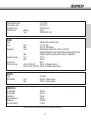
TECHNICAL SPECIFICATIONS
ENGINE
125 cc. engine
Cylinder size
Bore and stroke
200 cc. engine
Cylinder size
Bore and stroke
250 cc. engine
Cylinder size
Bore and stroke
280 cc. engine
Cylinder size
Bore and stroke
300 cc. engine
Cylinder size
Bore and stroke
Carburettor, diameter of the diffusor
Lubrication system
Ignition system
TRANSMISSION
Transmission type
Clutch type
Driving system
Gear ratio
2 stroke, single cylinder, direct reed valve crankcase induction. Liquid cooled.
124,8 cc.
54 x 54.5 mm.
175,3 cc.
64 x 54,5 mm.
247,7 cc.
72,5 x 60 mm.
272,2 cc.
76 x 60 mm.
294,1 cc.
79 x 60 mm.
26
Mixture (50:1)(2%)
Digital magnetic flywheel CDI
6 gears, Four / Six system by GAS GAS* (Patented).
Hydraulic command, 1/3 discs, variable progressive with diaphragm system by GAS GAS* (Patented).
By chain
1st. 2,996 (35x27x28/16x24x23)
2nd. 2,571 (36/14)
3th. 2,187 (35/16)
4st. 2,112 (36x23x24/14x28x24)
5st. 1,125 (27/24)
6th. 0,821 (23/28)
-10-
Primary reduction ratio
Final reduction ratio
Overall drive ratio
Transmission oil
FRAME
Type
Tyres
Suspension
Suspension stroke
Front fork oil
Front fork oil level
BRAKES
Type
Disc diameter
DIMENSIONS
Overall height
Overall width
Seat height
Ground clearance
Wheelbase
Fuel tank capacity
Capacity
Type
2,777 (75/27)
3,818 (42/11)
8,704 (6th. gear)
550 cc.
10W40 API SF o SG.
Tubular profile made with Cr-Mo.
2,75 x 21” Trial
4,00 x 18” Trial tubeless.
Adjustable tele-hydraulic fork ø 40 mm. (125 / 200).
Adjustable tele-hydraulic fork ø 40 mm with aluminium bars (250 / 280 / 300)
Rear
Variable progressive system with mono-shock multiadjustable.
Front
177 mm.
Rear
164 mm.
SAE 5.
ø 40 mm.(125 / 200)
180 mm. air chamber steel bar
ø 40 mm. (250 / 280 / 300) 160 mm. air chamber aluminium bar
Front
Rear
Front
Front
Rear
Disc brake.
ø185 mm. 4 piston calipers.
ø150 mm. 2 piston calipers.
1180 mm.
820 mm.
650 mm.
315 mm.
1330 mm.
3,1 liters.
(Specifications subject to change wothout notice, which may not be applicable in every country).
-11-
5
6
8
9
15 16 17 18
19
7
22
23
24
25
26
27
21
10
11
12
13
14
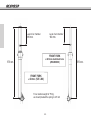
1 Front fender
2 Front brake caliper
3 Front suspension left
bottle
4 Front suspension bar
5 Breather hose
6 Spark plug
7 Filter box
8 Rear fender
9 Rear headlight
10 Front tyre
11 Front brake disc cover
12
13
14
15
16
17
18
19
20
21
22
23
20
28
Front brake disc
Cylinder
Carburettor
Chain guide
Chain slide
Chain
Rear sprocket cover
Rear sprocket
Rear rim
Rear tyre
Exhaust protection
Frame
-12-
29
31 32
30
24
25
26
27
28
29
30
31
32
33
34
35
33
34
Middle silencier
Radiator
Headlight
Front tyre air valve
Rear brake disc
Sidestand lever
Swingarm
Rear brake lever
Kickstart pedal
Water pump
Exhaust pipe elbow
Front wheel axle
35
44
45
36
37
38
39
40 41
42
43
46
47
48
49
50
51
52
61
53
54
57
58
55
60
59
56
36
37
38
39
40
41
42
43
44
Rear fender
Axis nut rear wheel
Left foot peg
Air filter box cover
Shift pedal
Ignition cover
Fuel tank
Fuel tank cap
Left hanle grip
45 Clutch lever
46 Light controls
47 Clutch pump
48 Handlebar
49 Left bottle regulation
50 Multifunction
51 Warning indicators
52 Right bottle regulation
53 Front brake pump
-13-
54
55
56
57
58
59
60
61
Throttle cover
Front brake lever
Throttle grip
Silencer
Right foot peg
Rear brake pedal
Exhaust pipe elbow
CDI Switch
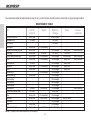
The maintenance table and adjustments are easy to carry out and must be done to insure the motorcycle is in good running condition.
MAINTENANCE TABLE
Part
Check /
Inspect
Adjust
Replace /
Change
Clean
Grease /
Lubricate
Rear shock absorver
Transmission oil
Front fork oil
Brake adjust
Swingarm and connecting rod
Spark plug
Throttle cable and twist grip
Chain
Reed valve box
Carburettor
Frame
Carburettor jet
Steering bearing
Piston bearing
Wheel bearing
Engine bearing
Rear sprocket
Cylinder and cylinder head
Brake
Brake disc
Clutch discs
Clutch
Engine protector plate
Every year
30 hours
Every race
Every race
Every race
Every race
Every race
30 hours
Every race
Every race
Every race
30 hours
60 hours
Every race
Every race
Every race
Every race
If is necessary
30 hours
If is necessary
If is necessary
If is necessary
If is necessary
First 5 hours
If is necessary
First 5 hours
im a fall
Every 2 years
60 hours
60 hours
If is damaged
60 hours
If is damaged
If is damaged
If is damaged
If is damaged
If is damaged
If is damaged
If is damaged
If is damaged
If is damaged
If is damaged
If is damaged
Every year
If is damaged
If is damaged
If is damaged
If is damaged
if is damaged
Every race
15 hours
If is necessary
Every race
Every race
Every race
Every race
Every 2 races
-
Every cleaning
Every cleaning
Every cleaning
.
Every cleaning
-
NOTE: (*) Inspect or do this operations only it’s necessary.
-14-
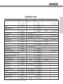
MAINTENANCE TABLE
Part
Check /
Inspect
Exhaust
Every race
Exhaust silencer fiber
Air filter
Every race
Steering assembly
Every race
Brake hose
Every race
Cooling fliud
Every race
General lubrication
Every race
Front and rear rims
Every race
Tyres
Every race
Brake oil level
Every race
Chain guide slide
Every race
Kickstart ang shift pedal
Every race
Brake piston pump amb his dustcover
Brake piston amb his dust-cover
Piston and piston rings
60 hours
Front and rear spokes
Every race
Fuel system
Every race
Front suspension
Every race
Exhaust o’ring
Bolts, nuts & fasteners
Every race
Fuel hose
Every race
Radiator hose set and connections
Every race
Frame protect sickers
Every race
Tire-silencer space
Every race
NOTE: (*) Inspect or do this operations only it’s necessary.
Adjust
Replace /
Change
Clean
Grease /
Lubricate
If is necessary
If is necessary
If is necessary
If is necessary
5 hours
If is necessary
If is necessary
If is necessary
If is necessary
Im a fall
500 hours
100 hours
If is damaged
Every 2 years
Every year
If is damaged
If is damaged
If is damaged
If is damaged
If is damaged
If is damaged
Every year
If is damaged
If is damaged
If is damaged
If is damaged
If is damaged
If is damaged
If is damaged
if is damaged
if is damaged
Every race
Every race
Every race
Every race
Every race
-
Every cleaning
Every cleaning
Every cleaning
Every cleaning
-
-15-
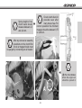
The new GAS GAS
TXT Pro carries the
a p p r o p r i a t e
certification plate
whose details should
coincide with those on
the accompanying
documentation and
the frame number
stamped on the
steering arm.
8
Homologation
conditions are detailed
on sheets 49 to 50.
A
B
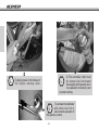
Serial number.
Enter the vehicle identification number (serial
number), the particulars shown on the model
label, and the ignition-key identification number
in the spaces provided, in order to simplify
your future orders for spare parts or as a useful reference
in the event of your vehicle being stolen.
I
Serial number (A)
This has been printed on the steering arm. It shows
the frame number used for registering this moped.
SERIAL N.
Homologation plate (B)
The moped carries a certification plate showing a serial
number that has also been printed on the front, and
this information must coincide with that contained in
the vehicle documents. We recommend that this
information be entered in the box below.
HOMOLOGATION P.
Key identification numbers
The moped carries one key set. The identification
number appears right on the key joints. This number
may be quoted when ordering a spare to replace a lost
key.
The model shown is the TXT PRO 200
KEY NUMBER
-16-
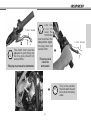
C
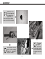
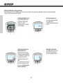
The control panel includes
lighting, turn signal, horn and
engine stop switches.
8
C
C
The indicator
control has been
located on the
underside of the left-hand
grip. This is an orange-colour
button. To start the right-hand
indicator, move this switch to
the right; and likewise, to start
the left-hand indicator, move
this switch to the left.
All light controls have been located
on the left-hand grip; the various
positions available are reached by
sliding the main switch, which is on
the left end of the grip.
8
-17-
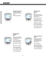
8
Located under the
suspension lower right side
bracket. For correct
operation, it is necessary
to turn the handlebar completamente
towards the right until it stops, insert
the key in the groove, turn it in
counterclockwise direction, press and
to turn it again in clockwise direction.
The key can now be removed and
the steering will remain locked.
C
C
Fuel tank capacity : 3,1 liters
Use premium gasoline with an octane rating equal to or higher
than that shown in the table.
OCTANE RATING METHOD
MINIMUM RATING
Antiknock Index (RON + MON)/2
90
Research Octane No. (RON)
98
I
Never leave the key in the
locked latch. If the steering
is turned with the key in
the latch it may be damaged and the
locking system could be damaged.
8
Gasoline is extremely flammable and can be explosive under
certain conditions. Always stop the engine and do not smoke.
Make sure the area is well ventilated and free from any source
of flame or sparks; this includes any appliance with a pilot light.
I
Never mix vegetal and mineral oils together. Too much oil may
be cause an excessive amount of fumes and spark-plug dirt.
Too little oil may cause engine damage or early wear.
-18-
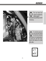
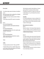
This engine is
designed tu burn
a mixture of
combustible fuels,
lead free petrol and oil.
C
C
The fuel tank cap is of the quick release type. To open the
cap, lift the tab and turn it 1/4 turn in counterclockwise
direction. To close it, place cap with the words GAS GAS in
the upper position, and turn the tab in clockwise direction.
It is important to check periodically the condition of the cap
sealing O’ring to insure proper sealing.
8
RECOMMENDS SYNTHETIC
2 CYCLE ENGINE OIL:
-19-
C
8
B
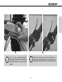
The choke (B) is a device
for aiding the engine start
if this is cold. The enigne
will get a good
temperature in a short
time and it won’t damage.
7
8
A
C
Reserve
Open
The position of the fuel tap (A)
must be forward rearward for
normal operation. When turned
upwards, it opens the reserve,
downwards it turns off the fuel.
-20-
Closed
C
The idle and petrol-air
mixture can be adjusted
by the screw as shown
in the illustration.
This play must never be eliminated.
3 mm. minium
This play must
never be
eliminated.
8
7
C
The clutch lever must be
adjusted to your liking, but
the free play should not
exceed 3mm.
C
7
3 mm. minium
Like the
c l u t c h
lever, the
front brake
lever must be in the
ideal position. Again,
the play must not
exceed 3mm,
-21-
I
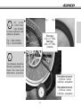
This is the position
the kick-start should
be in when not being
used.
8
A
C
When topping up
the oil, open the
cap (A).
Engine
Oil
capacity 550 cc.
(10W40).
B
The engine crankcase
drain cap is situated on
the lower left-hand side.
The drainage hole in the
crankcase allows its easy emptying.
C
8
8
To check the oil level, first make sure
the motorbike is perpendicular to the
ground. If the bike has been in use,
wait a few minutes. To check the oil level, unscrew
the cap (B) and examine the level of oil using the
dip-stick. The level should be between the marked
maximum and minimum levels. If it is too high,
drain the excess. If it is too low, add the necessary
quantity by opening the oil cap. Use the same
type and make of lubricant as that which is already
in the engine.
C
-22-
It is important to periodically
check the air filter. Open
the door set on the side of
the motorbike as shown in
the photo. Clean with water and
detergent, then dry and lubricate with
oil designed for filters. Ensure its
correct collocation once clean. In the
lower part of the filter chamber there
is a leaf that acts as the escape valve
for the liquids and/or other materials
that may build up in the filter chamber.
Check this valve is working properly.
C
7
-23-
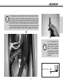
I
Remove the fuel tank,
out
located in the upper area
of the chassis, before
servicing the motor or
any other internal part of
the motorcycle. To do
this, first check that the
gasoline cap and fuel
cock are closed properly.
Next pull out the fuel tube
end (A) which is inserted
in the fuel cock. The third
step is to unscrew the
Allen screw M6 (B)
fastening the front upper
part of the tank . Once
the fuel tank is released,
lift it at the front section
and remove the tank
completely out the inside
of the chassis (C).
A)
B)
C)
Coolin
g fl
-30ºC uid
I
When filling the radiator,
use cooling fluid
designed for lightweight
alloy motors.
The engine must be
cool before removing
the radiator cap or
when replacing radiator
coolant, or severe scalding may
result.
-24-
8
7
C
It is necesassary to periodically check the spark plug condition.
This must be done removing the spark plug from its housing
in the upper part of the cylinder head. First disconnect the spark
plug cap and remove the spark plug using an adequate wrench.
Clean the spark plug with compressed air to remove dirt and
prevent foreign material to enter inside the engine compartment.
7
I
It is necessary to
periodically check the
state of the spark
plug. The sparking
plug distance should
be between 0.6 and
0.7mm.
~ 0,7 mm.
0,6 _
-25-
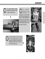
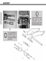
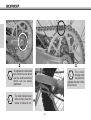
To carry out any type of operations on and improve access to the carburettor, it is recommended
to remove the filter box. You must follow these steps:
1.- Loosen the admission port clamp.
2.- Unscrew 4 tapered Allen screws M6 which are used to anchor the filter box to the chassis.
3.- Pull the filter box straight up just enough until the rear intallation connecting fixture is visible.
4.- Disconnect the fixture (Fig. 1).
5.- Remove the filter box completely (Fig. 2).
The carburettor is now exposed and can be separated from the motor assembly by loosening the reed box
port clamp.
C
Fig. 1
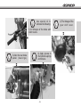
7
Loosen the two screws of the carburettor upper cover to allow the carburettor body being ready for cleaning
(Fig. 3).
-26-
Fig. 2
18,50 mm
7
Fig. 3
7
7
I
C
It is important to check the
level of petrol within the
carburettor. The float should
be at 18.5mm.
C
It is necessary to clean the
carburettor very thoroughly.
To do so use compressed air.
C
Extreme precautions must be
taken to dry the inside of the
carburettor thoroughly. Water
droplets, dirt, or other forign
material may enter and damage
the reed box and consequently
cause damages to the piston
and cylinder assembly.
Dismantle and clean
periodically the main nozzle
after washing the bike, as
well as cleaning the inside of
the carburettor housing.
-27-
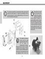
C
Since this is the last
door of access to the
inside of the cylinder,
special precautions
must be taken to keep it in
good condition and to monitor
its performance periodically.
Cover the cylinder bore with
a clean shop towel to prevent
foreing material to enter the
compartment when handling
these parts.
The reed box assembly is composed of only one body, the
reeds and reed keepers. To inspect the assembly remove
it by removing the 4 screws (A) attaching it to the rear of
the left and right crankcases.
I
(A)
-28-
7
The distance between
reeds and the reed
keeper should be 6,5 mm
for all types of
displacement models.
Reeds must be kept in perfect
conditions with no signs of nicks,
scratches, broken or folded sections.
Otherwise, the reed assembly must
be replaced with a new one.
7
C
Spring height of the
clutch stack should
measure between 4,3
and 4,4 mm.
9,75 +0.1
0
C
Check clutch discs for
possible wear after
many hours of use. For
correct operation the minimum
measure should be between 9,75
to 9,85 mm.
+1
17,5+0
C
7
After any removal or assembly
operations on the clutch lifter
circuit air trapped inside must
be purged by connecting an air bleeder.
7
C
(A) The circle indicates
where the engine oil
should be poured in
A
-29-
Level of air chamber
Level of air chamber
180 mm.
160 mm.
FRONT FORK
ø 40 mm. aluminium bars
(250/280/300)
575 mm.
FRONT FORK
mm. (125 / 200)
ø 40
For a medium weight of 75 Kg.
we should preload the spring to 2.5 mm
-30-
575 mm.
The preloading of the damper spring
is measured by the rotation of the
toothed rings (C) with the aid of a
special wrench.
7
Right (hydraulic extension).
Left (hydraulic compression).
C
7
C
The front suspension
is adjusted manually
B
C
A
7
C
Theshock
hidraulic
brake
absorber
compression can be
adjusted by turning
the screw (D)
located in the lowest
area of the shock
absorber it should
be at the mid point
of his career.
-31-
D
7
The regulation is done
by turning one screw
(A) located in the axis
of the suspension tube cap.
The bleeder (B) is used to purge
air that may be trapped inside
the slider.
C
7
7
C
Ii is very importante to
periodically remove and
verify the condition of
the swingarm bearings
and holders.
-32-
The link adjustments at the
lower part of rear
suspension must be
periodically cleaned, verified
and lubricated with grease.
C
Use special oil to
lubricate the following:
8
C
4) Apply grease to
the footrests springs
and fixtures.
8
8
C
3) Also the rear brake
pedal (bearings).
-33-
C
8
1) All linkages of the brake and
clutch levers.
2) The linkage of the
gear shift lever.
8
8
C
6) The secondary chain must
be cleaned and lubricated
thouroughly and frequently since
it is exposed to inclemency and
constant rubbing
C
5) Apply grease to the linkage of
the engine starting lever.
7
7) Lubricate the handlebar
with a fine coat of oil to
allow smooth operation of
the gasoline control.
C
-34-
7
7
C
8) It is also recommended to
frequently lubricate the chain tensor
spring because ii is under great
stress.
C
-35-
9) Oil and clean the gas control frequently; it is
especially recommended to do so after the bike
has been cleaned with water under high pressure.
7
7
C
The chain tension must
allow a slack near the
tensor of about 2 cm.
C
The chain
linkage must
be placed in
opposite direction of the
wheel travel.
7
C
To regulate the chain slack
and center the rear wheel
use the shaft excentrics
which can be easily
graduated.
-36-
Fig. 1
7
C
All
tyres
conditions
must checked
to insure optimum road
adherence possible.
Front tyre:
2,75 x 21” TRIAL
Rear tyre:
4,00 x 18” TRIAL
(tubeless)
Fig. 1 - Bad condition
Fig. 2 - Good condition
7
C
Fig. 2
Tyre pressure should be
checked periodically to
insure the best road
adherence possible.
Front wheel pressure:
0,450 bar - normal
0,420 bar - competition
Rear wheel pressure:
0,350 bar - normal
0,300 bar - competition
-37-
Pad brakes wear,
front and rear, must
be checked from
time to time to
insure an efficient braking
power under all circumstances.
C
8
7
7
C
The front brake fluid level
can be verified watching
through the transparent
inspection window.
7
-38-
C
The brake
calipers
have been
furnished with bleeder
valves to eliminate the
air trapped in the brake
circuit.
7
C
The rear brake fluid
reservoir is located at the
cylinder support.
Verify fluid level periodically and refill
if necessary.
To verify the reservoir
level you must remove
the fuel tank, and place
de oil reservoir in horizontal position
to check the real fluid level.
Must be filled between the marks
MIN & MAX.
C
MAX
MIN
-39-
PART NAME
C
H
A
S
S
I
S
Front wheel axle
Chassis to swingarm fastener
Upper shock absorber fastener
Lower shock absorber fastener
Connecting rods caps
Handlebars
Hand levers
Radiator fasteners
Front bridge wing
Brake pedal
Muffler fasteners
Rear wheel axle
Rear brake caliper fastener
Front brake caliper fastener
Exhaust pipe elbow fastener
Engine fasteners
Rear brake pump fastener
N-m
PART NAME
40 - 50
60 - 70
40 - 50
40 - 50
40 - 50
18 - 25
7 - 10
7 - 10
7 - 10
27 - 32
18 - 25
40 - 50
27 - 32
27 - 32
27 - 32
18 - 25
7 - 10
E
N
G
I
N
E
-40-
Spark plug
Ignition fasteners
Cluth fasteners
Cylinder stud bolt fasteners
Reeds fasteners
Clutch ground fastener
Crankcases fasteners
Water pump cap fastener
Clutch cap fastener
Flywheel fastener
Water fastener
Ignition cap
Engine drain plug
Kickstart pedal screw
Shift pedal screw
Cylinder head screws
Cylinder nut
N-m
11
7-8
7-8
25
7-8
3-4
7-8
7-8
7-8
40
10
7-8
12
12 - 13
7-8
11,5 - 13
25
STORAGE
For extended storage of the motorcycle, you must do the following:
- Clean the motorcycle thoroughly.
- Start the engine for about 5 minutes to warm up the transmission oil and then drain it (see “crankcase drain cap” page 22).
- Fill with new transmission oil.
- Empty the fuel tank (gasoline will deteriorate if left too long).
- Lubricate the chain and all cables.
- Cover all unpainted metal surfaces with a coat of oil to prevent rust, do not apply oil to the brakes and rubber parts.
- Cover the exhaust pipe with a plastic bag to prevent corrosion.
- Place the motorcycle in such a position so that the wheels do not touch the ground (if possible, place cardboards
under the wheels).
- Cover the motorcycle to protect it from dust and dirt.
When starting off after an extended storage:
- Remove the plastic bag from the exhaust pipe.
- Tighten the spark plug.
- Fill the fuel tank.
- General lubrication.
- Inspect tyre pressure and inflate to the specified pressure, if necessary.
I
To avoid excessive ageing of the plastic parts and other washable pieces of the motorcycle, it is suggested
that these items must be washed carefully. If the washer applies water at high pressure and/or temperature,
take the precaution of maintaining the washer outlet gun at a distance of 30 centimeters minimum, this
will insure the correct gloss of the plastics and adherence of the self-adhesive labels that decorate the
motorcycle.
-41-
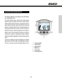
GAS GAS MULTIFUNCTION INSTRUCTIONS
The multifunction apparatus, which is waterproof, has 2 LED indicators
on a central indicator screen.
This central indicator screen, made of liquid crystal and with
illumination, gives information about the rpm, speed, distance
travelled, total kilometres travelled, time, average speed, maximum
speed, ambient temperature, length of time with motor running and
total time. The odometer and the control for the total time with motor
running save the data to the memory, even when the device is
switched off. When the multifunction apparatus is not activated, it
displays a clock.The value of the wheel circumference can be altered,
as well as the system of measurement (metric or British).
The ambient temperature is displayed on the upper left-hand part of the
screen.
The screen can display the engine temperature from an optional
temperature sensor. If this is too high, a warning LED lights up in yellow.
If the rpm are too high, the second warning LED lights up in red.
1.
2.
3.
4.
5.
6.
-42-
Yellow warning LED
Red warning LED
Right-hand button
MODE button
Left-hand button
Central display screen
Technical characteristics
FUNCTIONS
SYMBOL
CURRENT SPEED
SPD:
TACHOMETER
RPM
TECHNICAL
CHARACTERISTICS
4
MS
DISTANCE TRAVELLED
DST
ODOMETER
0.1 kmph or mph
+/- 0,1%
+/- 0,1%
Variable
+/- 0,1%
0.1 kmph or mph
+/- 0,1%
0.0 - 19999 km or mi.
0.1 kmph or mph
+/- 0,1%
- 9999 hours 59 minutes
1 second
+/- 0.1%
1
+/- 0,1%
0
MAXIMUM SPEED
TT
4
0
PRECISION
10 rpm
0 -19999 rpm
TACHOMETER BAR
TIME RUNNING
- 399.9 kmph or mph
INCREMENTS
-12000 rpm.
- 399.9 kmph or mph
ODO
0.0 – 999999
OPERATION TIME
RT
0 - 999 hours 59 minutes
1 minute
+/- 0.1%
OPERATION TIME
ACCUMULATED
ART
0 - 9999 hours 59 minutes
1 minute
+/- 0,1%
00:00:00
12:59:59 or 23:59:59
+/- 0,1%
LO
Approximately 1 year life
+/- 0,1%
CLOCK
BATTERY LOW
TYRE SIZE
0
- 3999 mm
Initial voltage: 9 - 400 V AC/DC..
Speed sensor: Non-contact magnetic sensor.
Tachometer input: Electrical pulse sensor.
Wheel circumference adjustment: 1 mm – 3.999 mm (1 mm increments).
Operating / storage temperature: from 0 ºC to 60 ºC (from 32 ºF to 140 ºF) / from -20 ºC to 80 ºC (from -4 ºF to 176 ºF).
Battery / life: 3V CR2032 / Approx. 1 year
-43-
Functions
ODO: Odometer
It shows the total mileage accumulated by the vehicle. The data is
stored in the memory, even when the device is not running.
RPM: Bar
Tachometer with bar graph. The bar graph of the tachometer displays
up to 12,000 rpm.
RPM: Digital Tachometer
The rpm are shown on the right side, second row. The digital
tachometer displays up to 12,000 rpm. The tachometer signal can
be captured from the sparkplug cable.
ART: Time of use controller
Calculates the total time in operation. It starts counting from the
moment the motor is turned on.
RT: Total time of use controller
It calculates the vehicle’s operation time since the last RESET
operation. It starts counting from the moment that movement begins.
The data is stored in the memory, even when the device is not
running.
Gear change indicator according to rpm
This function permits setting an indicator for changing gears at a
specific rpm level. The red LED warning light flashes when the rpm
reaches the specific level and stops flashing when the gear is
changed.
12/24 hour clock
It shows the time in either 12 or 24 hour formats.
SPD: Speedometer
The speedometer information appears in the centre of the screen.
It shows up to 399.9 kmph or mph.
Ambient temperature / engine temperature gauge
The ambient temperature is displayed on the upper left-hand part of the
screen.
The screen can display the engine temperature from an optional
temperature sensor. If this is too high, a warning LED lights up in yellow.
MS: Maximum speed gauge
It shows the highest speed reached since the last resetting of the
data.
High rpm gauge / Gear change warning according to rpm
If the rpm are too high, the second warning LED lights up in red.
This function permits setting an indicator for changing gear at a
specific rpm level The red LED warning light flashes when the rpm
reaches the specific level and stops flashing when the gear is
changed.
DST: Distance travelled
This appears on the right side, in the second line of the screen. The
TRIP function contains the vehicle’s accumulated mileage since the
last RESET operation.
-44-
Setting the multifunction display parameters
After confirming each value, the display goes from one screen to the next until all have been displayed. If no button is pressed, the display
returns to the home screen after 15 seconds.
Activating adjustment mode
To start setting mode for the
multifunction display, press
buttons 1, 2, and 3
simultaneously for 3 seconds,
and then release.
Selecting the speed unit
To change between kmph and
mph, press button 1.
Confirm the selection by pressing
button 2.
Selecting the values for the
wheel circumference
Enter the value for the wheel
circumference by pressing button
1 in succession. To go on to the
next digit, press button 3.
Confirm by pressing button 2.
Note:
If you do not know the value of
the wheel circumference, see
the section on "Measuring the
wheel circumference"
Selecting the time format
To change between the 12 and
24 hour clock, press button 1.
Confirm by pressing button 2.
-45-
Setting the time
Enter the value for the time by
pressing button 1 in succession.
To go on to the next digit, press
button 3.
Confirm by pressing button 2.
Setting the pulse per
revolution (PPR)
The gauge receives one
electrical pulse for each
revolution on the engine (PPR).
Default value for 2 and 4 stroke
engines: 1 PPR.
Enter the value by pressing
button 1 in succession. To go on
to the next digit, press button 3.
Confirm by pressing button 2.
Setting the pulse per
revolution (PPR)
Note:
This step is only to be taken on
vehicles that change the type of
PPR pulse at a specific number
of rpm.
If you do not know this value,
press button 2 to go on to the
next screen.
Setting the pulse per revolution
(PPR)
Note:
This step is only to be taken if a
value of 0 was entered in the
previous step.
Default value: 1.0
If you do not know this value,
press button 2 to go on to the
next screen.
Enter the value by pressing
button 1 in succession. To go on
to the next digit, press button 3.
Confirm by pressing button 2.
Enter the value by pressing button
1 in succession. To go on to the
next digit, press button 3.
Confirm by pressing button 2.
-46-
Selecting the temperature unit
To change the temperature
display between ºC and ºF, press
button 1.
Confirm by pressing button 2.
Selecting the warning
temperature
Note:
This step can only be taken on
vehicles fitted with the optional
temperature sensor.
When the engine temperature
exceeds the set value, the
warning LED on the left lights up.
Default value: 90 °C (190ºF)
Enter the value by pressing
button 1 in succession. To go on
to the next digit, press button 3.
Confirm by pressing button 2.
Selecting the danger
temperature
Note:
This step can only be taken on
vehicles fitted with the optional
temperature sensor.
When the engine temperature
exceeds the set value, the
warning LED on the right lights
up.
Default value: 110 °C (230ºF)
Enter the value by pressing
button 1 in succession. To go on
to the next digit, press button 3.
Confirm by pressing button 2.
Selecting the rpm for a gear
change
When the set rpm is reached,
the left-hand warning LED
flashes to show that the gear
must be changed.
Default value: 6000 rpm
Enter the value by pressing
button 1 in succession. To go on
to the next digit, press button 3.
Confirm by pressing button 2.
-47-
Selecting the danger rpm
When the set rpm is reached,
the right-hand warning LED
flashes to show that the rpm on
the engine are too high.
Default value: 10000 rpm
Enter the value by pressing
button 1 in succession. To go on
to the next digit, press button 3.
Confirm by pressing button 2.
Total reset of the display
Press the RESET button, using a suitable object. The display will
start from zero, except for the data for total accumulated distance
and time.
Resetting the display functions after each use of the vehicle.
Internal battery
The display is powered by an internal 3 V battery, type CR2032.
When the voltage in the internal battery drops below 2.45V, the
screen displays LO.
To change the battery, open the cover behind the display, and use
a coin to unscrew it counter-clockwise. Make sure that the positive
terminal on the battery is facing upward.
After each use of the vehicle, the following functions can be reset
simultaneously:
- Maximum speed
- Distance
- Chronometer
- Maximum temperature
- Maximum rpm
Confirm the reset by pressing buttons 1 and 2 simultaneously.
-48-
Screen options
When the display is powered by the internal battery only, the screen
lights up partially for 3 seconds when the button is pressed.
If the lighting is connected to the 12V system on the vehicle, it will
be brighter and stay on for up to 20 minutes after the vehicle has
come to a full halt.
The multifunction display shows all the information on three different
screens.
While in motion, screens 1 and 2 are on display. Screen 3 is displayed
for 3 seconds, and then returns to screen 1.
To change from one screen to another, press button 2 ("Mode") in
succession.
To edit the distance travelled (DST), keep button 3 pressed down.
Sleep Mode
If the multifunction display does not receive any information for 20
minutes (signal from wheels turning or a button pressed), the screen
goes off, showing only the time. When the vehicle starts or a button
is pressed, it will start up again.
Screen 1:
Screen 1 shows the following information:
- Speed, distance travelled, time, ambient temperature, tachometer (bar).
Screen 2:
Screen 2 shows the following information:
- Speed, digital tachometer, time in motion, time in operation, engine
temperature*, tachometer (bar).
Screen 3:
Screen 3 shows the following information:
- Maximum speed, danger rpm, accumulated time in operation,
odometer, maximum temperature*.
Measuring the wheel circumference
Method 1
Measures the diameter of the front wheel. Multiply the diameter by
3.14 and, if necessary, convert the measurement into mm by
multiplying the figure obtained by 25.4. The measurement obtained
is the size of the wheel circumference.
Method 2
On a smooth, flat surface, make a mark on the side of the tyre where
it touches the ground. Move the vehicle forward until the tyre has
made a complete turn, and the mark is back at the lowest point.
Make a new mark on the ground at this point.
Measure the distance between the marks on the ground and, if
necessary, convert the measurement into mm by multiplying the
figure obtained by 25.4. The measurement obtained is the size of
the wheel circumference.
To obtain a more precise measurement, the driver must remain on
the vehicle while taking measurements.
*Optional
Lighting
The display is powered by an internal 3 V battery, type CR2032.
To change the battery, open the cover behind the display, and use
a coin to unscrew it counter-clockwise. Make sure that the positive
terminal on the battery is facing upward.
-49-
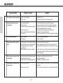
TROUBLESHOOTING
NOTE
This is not an exhaustive list of malfunctions, it only shows the most common problems.
POSSIBLE CAUSE
REMEDY
- Seized crankshaft.
- Seized cylinder / piston / jornal bearing.
- Seized transmission assembly.
- Motorcycle inactive too long.
- Go to a specialized workshop.
- Go to a specialized workshop.
- Go to a specialized workshop.
Drain old fuel out of the tank. With the fuel tank filled with
new fuel, the engine will start immediately.
- Clean and dry or replace the spark plug.
- In order to "relieve the engine", accelerate to max. speed,
press the starter pedal 5 or 10 times. Then, start the engine
as described above. If the engine fails to start, remove the
spark plug and dry it.
- Clean the fuel tank air vent. Adjust the air cleaner duct.
- Verify the exhaust valve and repair as necessary.
MALFUNCTION
1
Engine does not crank
- Wet or fouled spark plug.
- Flooded engine.
- Incorrect air/fuel mixture.
- Exhaust valve stuck open
2
Engine cranks but then stops
- Incorrect air supply.
- Close the starter. Clean fuel tank air vent. Adjust the air
cleaner duct.
- Fill up the fuel tank.
- No fuel.
3
4
Engine overheating
The engine operates irregularly
- Insufficient cooling liquid in the circuit.
- Radiator is dirty or partially restricted.
- Fill up cooling liquid, verify the refrigeration system
watertightness.
- Clean radiator fins or replace it.
- Spark plug dirty, or misadjusted.
- Poor contact with the spark plug cap or
cable loose in cap.
- Verify the spark plug condition and clean it accordingly,
tighten or replace it.
- Verify the spark plug cap condition. Replace if deteriorated.
-50-
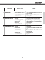
MALFUNCTION
POSSIBLE CAUSE
REMEDY
4
The engine operates irregularly
- Ignition rotor damaged.
- Water in fuel.
- Replace the rotor.
- Drain the fuel tank and fill up with new fuel.
5
Engine lacks power or poor
acceleration
- Fuel supply defective.
- Dirty air cleaner.
- Leaking or deteriorated exhaust system.
- Dirty carburetor jets.
- Worn or damaged crankshaft bearings.
- Clutch slips.
- Clean the fuel system and verify its operation.
- Clean or replace the air cleaner. Verify its operation.
- Verify if the exhaust system is damaged. Replace the
muffler fiberglass packing, if necessary.
- Disassembly the carburetor and clean all jets.
- Replace the crankshaft bearings.
- Verify the clutch operation. Go to a specialized workshop.
6
Abnormal engine noise
- Ignition problem.
- Overheating.
- Go to a specialized workshop.
- Refer to section 5.
7
Detonations from the exhaust
pipe
- Carbon build up in combustion chamber.
- Incorrect octane or poor quality gasoline.
- Damaged spark plug or incorrect
specifications.
- Deteriorated exhaust system gaskets.
- Clean the combustion chamber.
- Drain all gasoline and fill up with a higher octane fuel.
- Replace the spark plug with a new one of the correct type.
- Verify if the exhaust system is damaged. All gaskets must
be in perfect conditions, otherwise replace them with new
ones if necessary.
8
White smoke coming out of the
exhaust pipe
- Deteriorated cylinder head gasket (water
leakage into the cylinder).
- Incorrect throttle valve cable adjustment.
- Replace the cylinder head gasket. Go to a
specialized workshop.
- Readjust the throttle valve cable.
9
Brown smoke coming out of the
exhaust pipe
- Restricted air cleaner.
- Clean or replace the air cleaner. Go to a specialized
workshop.
- Verify main jet operation. Go to a specialized workshop.
- Main jet set too high.
-51-
MALFUNCTION
POSSIBLE CAUSE
10
Gears do not engage correctly
- Clutch does not disengage.
- Bent or seized shift fork.
- Gear seized at the transmission.
- Damaged gearshift lever.
- Broken or loose selector position spring.
- Broken spring in the reverse selector
mechanism.
- Broken spring in the reverse selector
mechanism.
- Broken gear drum.
- Broken spring in the gear selector ratchet.
- Go to a specialized workshop.
- Replace the shift fork.
- Go to a specialized workshop.
- Replace the gearshift lever.
- Adjust or replace the selector position spring.
- Replace the spring in the reverse selector
mechanism.
- Replace the spring in the reverse selector
mechanism.
- Replace the gear drum.
- Replace the spring in the gear selector ratchet.
11
Jumps out of gear
- Shift fork worn at the gears.
- Worn gear grooves.
- Worn gear dogs.
- Worn shift drum groove.
- Worn shift fork shaft.
- Broken selector drum position spring.
- Broken gears.
- Replace the shift fork.
- Replace. Go to a specialized workshop
- Replace. Go to a specialized workshop.
- Replace. Go to a specialized workshop.
- Replace shaft. Go to a specialized workshop.
- Replace the spring. Go to a specialized workshop.
- Go to a specialized workshop.
12
Clutch slips
- No clutch lever free play.
- Worn clutch friction plate.
- Worn clutch center hub.
- Broken or weak clutch spring.
- Unevenly worn clutch discs.
- Go to a specialized workshop.
- Replace the clutch friction plate.
Go to a specialized workshop.
- Replace the clutch center hub.
- Adjust or replace the clutch spring.
- Replace the clutch discs. Go to a specialized workshop.
- Cable interferes with the handlebar turns.
- Steering stem locknut too tight.
- Damaged or worn steering bearings.
- Bent steering stem.
- Move or loosen the cable just a little.
- Loosen the steering stem locknut.
- Replace the steering bearings.
- Replace the steering stem. Go to a specialized workshop.
13
The motorcycle is unstable
-52-
REMEDY
MALFUNCTION
14
15
16
Shock absorber set too hard
Shock absorber set too soft
Abnormal motorcycle noises
POSSIBLE CAUSE
- Excessive front fork oil.
- Front fork oil viscosity too high.
- Bent front fork.
- Pour excess oil until reaching the correct oil level.
- Drain fork oil and fill with correct fork oil viscosity.
- Replace the front fork. Go to a specialized workshop.
- Tire air pressure set too high.
- Incorrect rear shock absorber adjustment.
- Check tire air pressure.
- Adjust rear shock absorber.
- Insufficient front fork oil.
- Front fork oil viscosity too low.
- Fill with fork oil until reaching the correct oil level.
- Drain fork oil and fill with correct fork oil viscosity.
- Bent front fork.
- Replace the front fork. Go to a specialized workshop.
- Incorrect rear shock absorber adjustment.
- Adjust the rear shock absorber.
- Incorrect drive chain adjustment .
- Worn drive chain.
- Adjust the drive chain.
- Replace the drive chain, rear sprocket and the secondary
transmission pinion.
- Replace the rear sprocket.
- Lubricate with appropriate chain oil.
- Align the rear wheel. Go to a specialized workshop.
- Add front fork oil until reaching the correct level.
- Replace the front fork spring.
- Change the disc brake.
- Reinstall or replace pad.
- Replace the damaged cylinder.
- Verify and adjust to the correct torque values.
- Worn rear sprocket teeth.
- Insufficient drive chain lubrication .
- Incorrect rear wheel alignment.
- Insufficient front fork oil.
- Weak or broken front fork spring.
- Worn disc brake.
- Pad installed incorrectly or surface glazed.
- Damaged cylinder.
- Improperly tightened brackets, nuts, bolts.
17
Handlebar vibration
REMEDY
- Worn tire, and worn swingarm or its
needle bearings.
- Wheel rim off-centre.
- Incorrect wheel alignment.
-53-
- Replace worn parts with new ones.
- Centre rim.
- Verify wheel spokes tension. Readjust if necessary.
MALFUNCTION
17
Handlebar vibration
POSSIBLE CAUSE
- Excessive steering axles tolerances.
REMEDY
- Loose handlebar bracket, and loose
handlebar stem locknut.
- Tighten steering bracket and steering stem locknut to the
correct torque values.
- Tighten steering bracket and steering stem locknut to the
correct torque values.
- Bent chassis.
- Incorrect steering adjustment.
- Bent steering stem.
- Bent front fork.
- Incorrect wheel alignment.
- Replace the chassis. Go to a specialized workshop.
- Adjust the steering. Go to a specialized workshop.
- Replace the steering stem. Go to a specialized workshop.
- Replace the front fork.
- Align the wheels.
18
Motorcycle pull to one side
19
Brakes do not operate correctly - Worn discs.
- Leaking brake fluid.
- Deteriorated brake fluid.
- Broken pump piston.
- Incorrect brake adjustment.
-54-
- Replace the discs.
- Verify the brake circuits. Replace the damaged or broken
parts.
- Drain the brake fluid and fill with the new fluid recommended
by the manufacturer.
- Replace the pump piston.
- Adjust brakes.
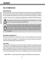
FINAL RECOMMENDATIONS
PREVENTIVE ADVICE
Before you ride the vehicle, take all the time you may require to check your motorcycle, carry out the periodical upkeep
and check all functions. In different sections of this manual you will find data and work specifications that must be
done at an autorized GAS GAS dealer, because of this and to extend the useful life of the motorcycle, all periodical
inspections must be carried out by specially trained professionals at a GAS GAS Post-Sale Service Shop.
Poor maintenance work of the motorcycle or not taking proper care of any problem, even if its
concern, can cause severe personal injury and may lead to death.
I
is a small
To avoid excessive ageing of the plastic parts and other washable pieces of the motorcycle, it is suggested
that these items must be washed carefully. If the washer applies water at high pressure and/or temperature,
take the precaution of maintaining the washer outlet gun at a distance of 30 centimeters minimum,
this will insure the correct gloss of the plastics and adherence of the self-adhesive labels that decorate
the motorcycle.
SAFE RIDING OF THIS MOTORCYCLE
Safe riding of a motorcycle does not only depend on the vehicle. The driver’s intelligence and common sense are
key factors to be taken into consideration. It is recommended that you practice your favorite sport wearing all the
necessary safety equipment (helmet, protection gear, boots, etc.).
LEGAL ADVICE
In the interest of technical development we reserve the right to modify the construction, the equipment and accesories
of the motorcycle. It is understood that all measurements, weights and power data must include their respective
tolerances. The photographs included in this manual may not match the model you have purchased. The descriptions
and the illustrations may vary depending on the volume of equipment and accesories of your motorcycle and also
of the versions exported. Because of this, there can be no liability except in case of errors, misprint or omission.
GAS GAS MOTOS, S.A. reserves the right to make changes and/or modifications at any time without notice.
-55-
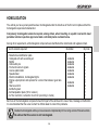
HOMOLOGATION
The vehicle you have just acquired has been homologated under the directives of the EU and complies with all the
homologation requirements demanded.
Compulsory homologation elements required, among others, when travelling on a public road and to meet
periodical vehicle inspection approval at state controlled plants are listed below.
Among other requirements, all homologation components are identified with a determined and registered mark.
List of elements required:
Illustration
- Manufacture identification plate
- Catalyzed with with secondary air
- Muffler
- Carburettor jets
- Front and rear turn signals
- License plate holder
- Speedometer
- Electrical installation, homologated lights
- Engine output pinnion and sprocket for a correct transmission gear ratio
- Horn
- Rearview mirror
- Antitheft system
- Antimanipulation plate (125 cc version)
- Air filter restriction; carburettor hood limit (according to model)
Available
Available
Available
Available
Available
Available
Available
Available
Available
Qty. /bike
1
1
1
1
1
1
1
1
1
1
2
1
1
1
Each one of the homologation components must form part of the vehicle and in case of loss, breakage or malfunction
it is recommended that the owner contact his official dealer to correct this problema.
Besides the homologated vehicle you have received a complementary kit for a racing version of this same vehicle.
Be advised that this version is not homologated.
-56-
HOMOLOGATION
12345678910111213141516-
Front right turn signal
Rear right turn signal
Trial rear pilot
Rear left turn signal
M6 Bolt
ULS screw 6x16
Phillips screw M6 x 25
Philips screw 6.3x16
Front left turn signal
Turn signal box
Trial license holder homologated
Stand spring
ULS screw 8x12 8.8
Self-locking M6 nut with galvanized washer
Mirrors
Carburettor kit
125 / 200
1
2
3
4
5
6
7
8
9
10
250 / 280 / 300
BT280634018
BT280634018
BT280334015
BT280634019
T2206000
x2
T0506016N x2
T0706025
x3
T0706316
x2
BT280634019
L300720
-57-
125 / 200
11
12
13
14
15
16
250 / 280 / 300
BT280520003
BE25610039
T0508012
T2206002
x3
L300760
x2
MT120690100 MT280690100